


Dynamic analysis of aircraft impacting on concrete structures
-
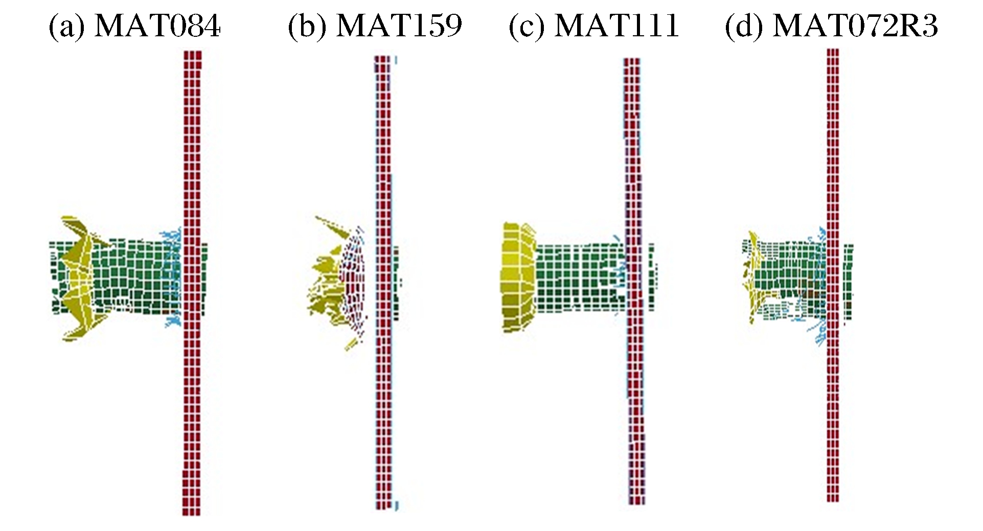
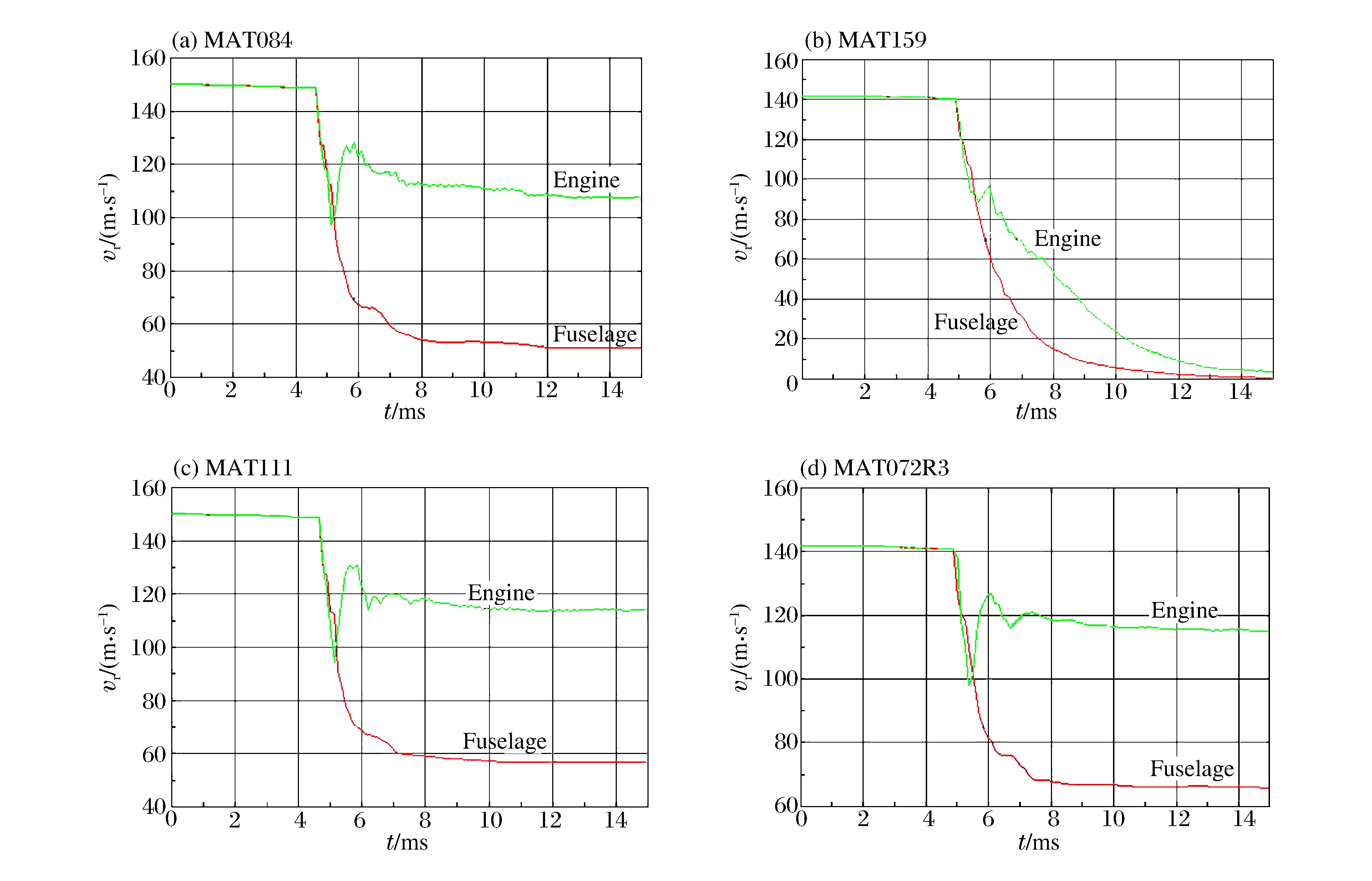
摘要: 基于已有的飞机撞击混凝土结构的实验数据,利用有限元分析软件ANSYS/LS-DYNA,选用可模拟冲击作用下混凝土性能的4种不同材料模型,在同一接触算法、同一失效准则下,进行飞机撞击混凝土结构的数值模拟与动力学分析,探讨了4种混凝土材料模型在模拟飞机撞击下混凝土结构破坏效应的能力。结果表明:4种混凝土材料模型均能模拟飞机撞击混凝土结构的穿入、散裂、碎甲等局部破坏效应,但在考虑正、背面破坏面积及剩余速度等因素时,MAT072R3和MAT084材料模型的计算结果与实验结果较接近,MAT111材料模型次之,MAT159材料模型有较大的差异。本文的研究结果可为后续评估混凝土结构安全壳抵抗飞机撞击能力时提供基础参数。Abstract: We carried out the analysis of aircraft crashing on the concrete structures through numerical simulation and dynamic analysis using the matured software of ANSYS/LS-DYNA. The analysis uses the same contacting algorithm for four different material models and the results of damage effects are discussed in detail. The numerical simulation results are listed as follows. First, all of four material models can simulate the crashing process of penetration, spallation, and some other local damage effects. Second, if the damage is in front and back side, multiplying with velocity is considered, though the results of MAT072R3 and MAT084 are close to each other. The result of MAT111 is not very close to the previous two models. The model of MAT159 is significantly different from the results of 3 models mentioned above. The results of this research provide some basic parameters for subsequent evaluation of concrete structures resisting under aircraft impact.
-
Key words:
- mechanics of explosion /
- impact of aircraft /
- material model /
- concrete structure /
- dynamic analysis
-
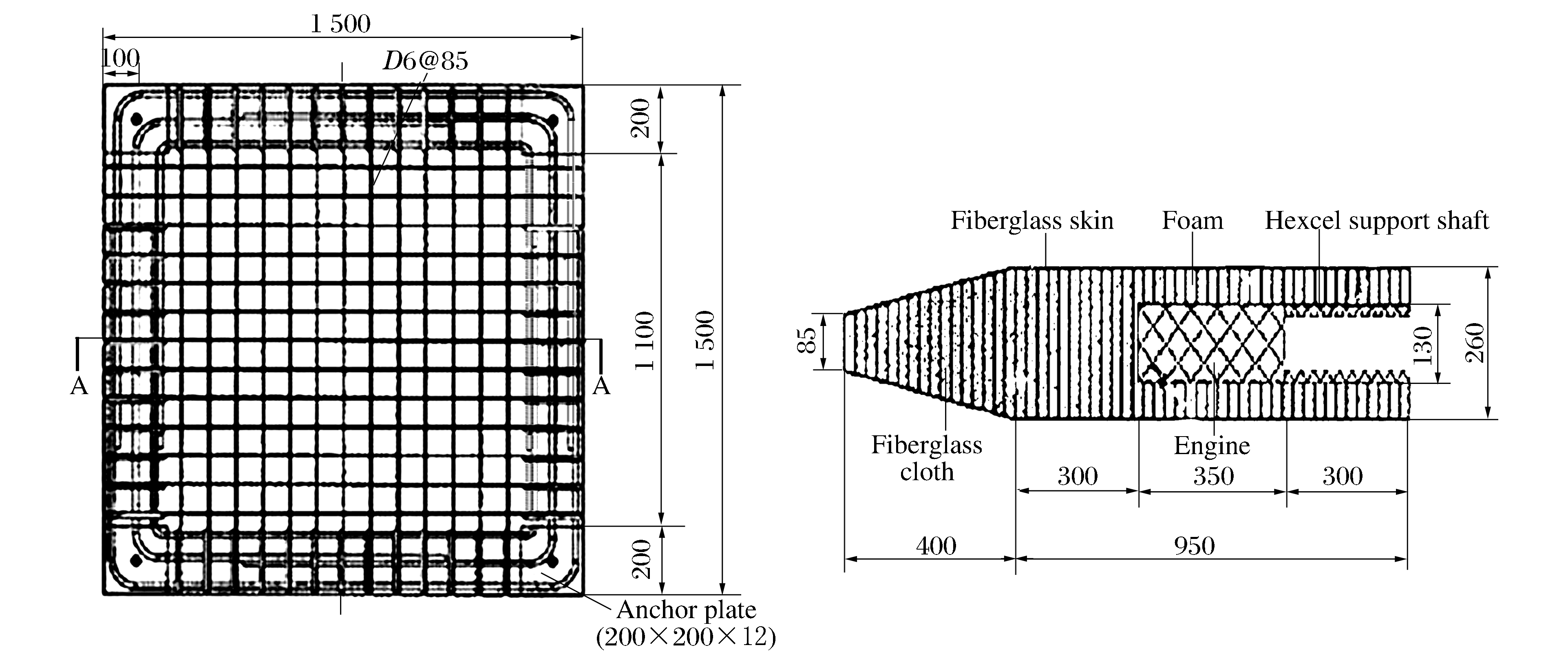
图 1 飞机撞击钢筋混凝土的实验模型剖面示意图
Figure 1. Schematic section of experimental model of aircraft crashing on the concrete structures

图 2 飞机撞击混凝土结构的有限元网格划分模型
Figure 2. Finite element mesh model of aircraft crashing on reinforced concrete
表 1 飞机模型的材料参数和重量
Table 1. The parameters and the weight of aircraft model
部件 材料 E/GPa Y/MPa εf W/N 机身外壳 玻璃 6.37 82.3 0.013 81.3 机身填充物 高密度泡沫 2.28 0.6 0.10 129.4 引擎 钢 206 797.4 0.20 28.1 赫氏支撑轴 碳纤维板 0.168 12.9 ∞ 6.8  下载: 导出CSV
表 2 数值分析结果与实验结果的对比
Table 2. Comparison of numerical and the experimental results
模型 v0/(m·s-1) vr/(m·s-1) dp/cm Ab/(cm·cm) 机身 引擎 实验 142 110 80 33 50×55 MAT084 142 108 52 30 39×42 MAT159 142 10 5 24 18×27 MAT111 142 113 58 18 30×33 MAT072R3 142 113 68 30 42×42
下载: 导出CSV
-
[1] US Nuclear Regulatory Commission. 10 CFR 50 Domestic licensing of production and utilization facilities[S]. Washington, DC: US Nuclear Regulatory Commission, 2009. [2] Nuclear Energy Institute. NEI 07-13 Methodology for performing aircraft impact assessments for new plant designs, Revision 7[S]. Washington, DC: Nuclear Energy Institute, 2009. [3] US Nuclear Regulatory Commission. RG 1.217 Guidance for the assessment of beyond-design-basis aircraft impacts[S]. Washington, DC: US Nuclear Regulatory Commission, 2011. [4] 中国国家核安全局. HAD101/04核电厂厂址选择的外部人为事件[S]. 1989 [5] 汤搏.关于核电厂防大型商用飞机撞击的要求[J].核安全, 2010(3): 1-12. http://www.cnki.com.cn/Article/CJFDTotal-HAQY201003003.htmTang Bo. Discussion on the impact of large commercial airplane to nuclear power plant[J]. Nuclear Safety, 2010(3): 1-12. http://www.cnki.com.cn/Article/CJFDTotal-HAQY201003003.htm [6] 李世民, 李晓军.几种常用混凝土动态损伤本构模型评述[J].混凝土, 2011(6): 19-22. http://www.cnki.com.cn/Article/CJFDTotal-HLTF201106006.htmLi Shi-min, Li Xiao-jun. Review on current dynamic damage constitutive models of concrete[J]. Concrete, 2011(6): 19-22. http://www.cnki.com.cn/Article/CJFDTotal-HLTF201106006.htm [7] 赵振东, 钟江荣, 余世舟.钢混结构物受外来飞射体撞击的破坏效应研究[J].地震工程与工程振动, 2003, 23(5): 88-94. http://www.cnki.com.cn/Article/CJFDTotal-DGGC200305015.htmZhao Zhen-dong, Zhong Jiang-rong, Yu Shi-zhou, et al. Study on damage to reinforced concrete structures by impacting of an aircraft[J]. Journal of Earthquake Engineering and Engineering Vibration, 2003, 23(5): 88-94. http://www.cnki.com.cn/Article/CJFDTotal-DGGC200305015.htm [8] 冯国忠.基于ANSYS/LS-DYNA的混凝土靶板侵彻问题的数值模拟与分析[D].中国地震局工程力学研究所, 2006. [9] 郭香华, 张庆明, 何远航.混凝土厚靶在弹体正侵彻下的响应研究[J].北京理工大学学报, 2011, 31(7): 765-767. http://d.wanfangdata.com.cn/Periodical/bjlgdxxb201107003Guo Xiang-hua, Zhang Qing-ming, He Yuan-hang. Study on behavior of semi-infinite concrete targets subjected to projectile normal penetration[J]. Transactions of Beijing Institute of Technology, 2011, 31(7): 765-767. http://d.wanfangdata.com.cn/Periodical/bjlgdxxb201107003 [10] 张晶, 贾宏光, 丁玲, 等.弹丸侵彻混凝土靶的数值模拟[J].弹箭与制导学报, 2012, 32(2): 89-98. http://www.cnki.com.cn/Article/CJFDTotal-DJZD201202025.htmZhang Jing, Jia Hong-guang, Ding Ling, et al. The numerical simulation of projectile penetrating into concrete target[J]. Journal of Projectiles, Rockets, Missiles and Guidance, 2012, 32(2): 89-98. http://www.cnki.com.cn/Article/CJFDTotal-DJZD201202025.htm [11] 陈仰光, 周羽.飞机撞击混凝土平板的动力学分析[C]//第15届全国结构工程学术会议论文集(第Ⅰ册).河南焦作, 2006. [12] Sugano T, Tsubota H, Kasai Y, et al. Local damage to reinforced concrete structures caused by impact of aircraft engine missiles: Part 2. Evaluation of test results[J]. Nuclear Engineering and Design, 1993, 140(3): 407-423. https://www.sciencedirect.com/science/article/pii/002954939390121O [13] Hossain Q A, Kennedy R P, Murray R C, et al. Structures, systems, and components evaluation technical support documents, DOE standard, accident analysis for aircraft crash into hazardous facilities[R]. Livermore, CA: Lawrence Livermore National Laboratory, 1997. [14] LS-DYNA keyword manual version 971[R]. Livermore: Livermore Software Technology Corporation, 2007. [15] Murray Y D. User's manual of LS-DYNA concrete material model 159[R]. Federal Highway Administration, 2007. [16] Tsubota H, Koshika N, Mizuno J, et al. Scale model tests of multiple barriers against aircraft impact: Part 1. Experimental program and test results[C]//Transactions of the 15th International Conference on Structural Mechanics in Reactor Technology. Seoul, Korea, 1999. [17] Tsubota H, Koshika N, Mizuno J, et al. Scale model tests of multiple barriers against aircraft impact: Part 2. Simulation analyses of scale model impact tests[C]//Transactions of the 15th International Conference on Structural Mechanics in Reactor Technology. Seoul, Korea, 1999. [18] Tsubota H, Koshika N, Mizuno J, et al. Scale model tests of multiple barriers against aircraft impact: Part 3. Analytical evaluation of multiple barriers against full-scale aircraft impact[C]//Transactions of the 15th International Conference on Structural Mechanics in Reactor Technology. Seoul, Korea, 1999. -

计量
- 文章访问数: 4416
- HTML全文浏览量: 573
- PDF下载量: 759
- 被引次数: 0