


Finite element analysis of load characteristic of liquid-filled structure subjected to high velocity long-rod projectile penetration
-
摘要: 为探讨高速弹体侵彻下蓄液结构的防护方法,采用瞬态非线性有限元,研究了高速杆式弹体侵彻下蓄液结构承受的冲击载荷特性,分析了冲击载荷的作用过程、前后板承受的载荷强度及其弹体初速度和水域尺度的影响。结果表明:弹体在蓄液结构中的初始开坑作用,将形成入射冲击波,其压力峰值极高,但作用时间短,并将在液体内产生多次反射;弹体在液体中的侵彻,将产生空化,并形成峰值小、作用时间长的空化压力载荷;后板对液体流的阻碍作用将形成出口局部高压;入射冲击波和出口局部高压的强度随着弹体初速度的增加而增大,随着水域长度的增加而不断减小。根据所受冲击载荷特性的不同,将前、后板分别划分为3个不同的区域,并建立了每个分区的简化计算模型。Abstract: To find effective protection for fluid-filled structures subjected to high-speed projectile penetration, we studied the characteristics of a structure bearing impact loads when undergoing high velocity rod projectile penetration using dynamic nonlinear finite element, and analyzed the process of the impact load, the load strength, the projectile initial velocity, and water scale, and their effects on the front and rear plates that bear the impact. Our results show that the initial penetrating effect (pit-opening) on the liquid-filled structure forms incident shock waves, which will have a high peak pressure but a short duration, and produce multiple reflections in the liquid. Along with the penetration process in the liquid, the cavitation will occur and result in a cavitation pressure load which will reach a small peak value with a long duration. Local high pressure load will be formed due to the rear plate hindering the liquid flow, and incident shock wave and local high pressure increase with the increase of the initial projectile velocity but decrease with the increase of the length of the waters. According to different characteristics of shock load borne by different parts of the structure, the front and rear plates are divided into three different areas, and a simplified model was established for each.
-
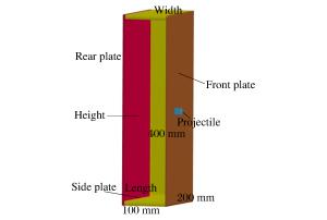
图 1 1/2蓄液结构计算模型示意图
Figure 1. Sketch of finite element modelfor half liquid-filled structure
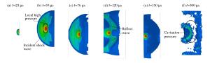
图 3 弹体侵彻蓄液结构载荷作用过程(v0=1 000 m/s)
Figure 3. Load process of the liquid-filled structure subjected to projectile penetration

图 7 前板的比冲量及压力峰值(v0=1 000 m/s, L=100 mm)
Figure 7. Specific impulses and peak pressures of the front plate
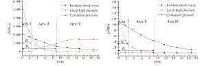
图 8 后板的比冲量及压力峰值(v0=1 000 m/s, L=100 mm)
Figure 8. Specific impulses and peak pressures of the rear plate
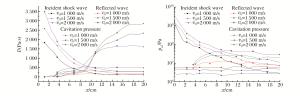
图 9 不同初速下前板的比冲量及压力峰值
Figure 9. Specific impulses and peak pressures of the front plate at different initial velocities
图 10 不同初速下后板的比冲量及压力峰值
Figure 10. Specific impulses and peak pressures of the rear plate at different initial velocities
图 11 不同水域长度下前板的比冲量及压力峰值
Figure 11. Specific impulses and peak pressures on the front plate at different lengths of waters
-
[1] Lecysyn N, Dandrieux A, Heymes F, et al. Ballistic impact on an industrial tank: Study and modeling of consequences[J]. Journal of Hazardous Materials, 2009, 172(2/3):587-594. http://cn.bing.com/academic/profile?id=cbce25e6101d6d2274427107153dea89&encoded=0&v=paper_preview&mkt=zh-cn [2] Disimile P J, Toy N, Swanson L A. A large-scale shadowgraph technique applied to hydrodynamic ram[J]. Journal of Flow Visualization & Image Processing, 2009, 16(4):1-30. http://www.wanfangdata.com.cn/details/detail.do?_type=perio&id=e4c766726c6f5629d9732baabe2cf211 [3] McMillen J H. Shock wave pressures in water produced by impact of smallspheres[J]. Physical Review, 1945, 68(9/10):198-209. https://www.researchgate.net/publication/243691996_Shock_Wave_Pressures_in_Water_Produced_by_Impact_of_Small_Spheres [4] McMillen J H, Harvey E N. A spark shadowgraphic study of body waves in water[J]. Journal of Applied Physics, 1946, 17(7):541-555. doi: 10.1063/1.1707751 [5] Disimile P J, Davis J, Toy N, et al. Mitigation of shock waves within a liquidfilled tank[J]. International Journal of Impact Engineering, 2011, 38(2):61-72. http://cn.bing.com/academic/profile?id=1ab5bf55e1ad5f29afacb898fefa4d91&encoded=0&v=paper_preview&mkt=zh-cn [6] Townsend D, Park N, Devall P M. Failure of fluid filled structures due to high velocity fragment impact[J]. International Journal of Impact Engineering, 2003, 29:723-733. doi: 10.1016/j.ijimpeng.2003.10.019 [7] Borg J P, Cogar J R, Tredways S, et al. Damage resulting from high speed projectile liquid filled metal tanks[C]//Wassex Institute of Technologies Press. 2001: 889-902. [8] Varas D, Zaera R, Lopez-Puente J. Numerical modeling of the hydrodynamic ram phenomenon[J]. International Journal of Impact Engineering, 2009, 36(3):363-374. doi: 10.1016/j.ijimpeng.2008.07.020 [9] Lecysyna N, Bony-Dandrieux A, Aprin L. Experimental study of hydraulic ram effects on a liquid storage tank: Analysis of overpressure and cavitation induced by a high-speed projectile[J]. Journal of Hazardous Materials, 2010, 178(1):635-643. http://cn.bing.com/academic/profile?id=210f94ef627d0d1fa1b4ca020b886c7a&encoded=0&v=paper_preview&mkt=zh-cn [10] Lecysyn N, Dandrieux A, Heymes F, et al. Preliminary study of ballistic impact on an industrial tank: Projectile velocity decay[J]. Journal of Loss Prevention in the Process Industries, 2008, 21(6):627-634. doi: 10.1016/j.jlp.2008.06.006 -

 下载:
下载:


计量
- 文章访问数: 4345
- HTML全文浏览量: 1029
- PDF下载量: 498
- 被引次数: 0