


Deformation field in 316L stainless steel by single shot peening
-
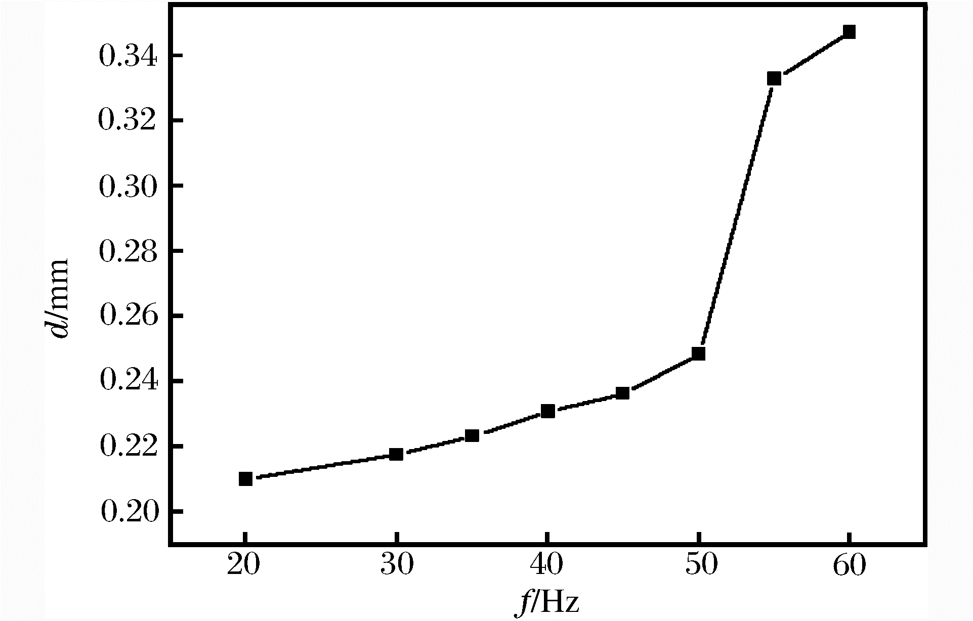
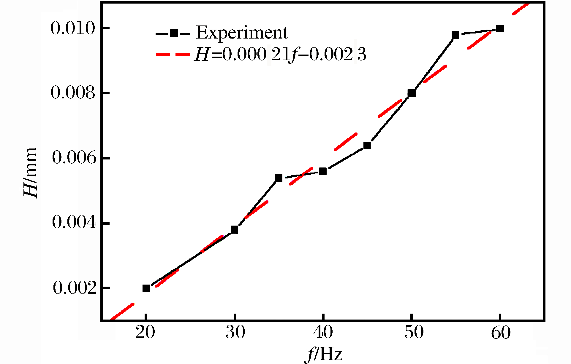
摘要: 运用金属材料表面纳米化试验机对单个弹丸撞击316L不锈钢表面进行了撞击实验;采用激光共聚焦显微镜观察了弹坑的三维形貌,测量不同振动频率下弹坑的直径及离面位移;采用云纹干涉法对弹坑周围的面内应变场进行测量,并分析振动频率及撞击方式对弹坑尺寸、塑性应变大小以及塑性应变区范围的影响;采用有限元方法对单个弹丸垂直撞击试件表面的应变场进行数值模拟,与实验结果进行比较,分析了弹坑周围残余应力的分布。结果表明:随振动频率的增加,弹坑直径和离面位移都增加,频率在50~55Hz,弹坑直径有突变,离面位移和振动频率呈线性关系;振动频率越大,塑性应变越大,塑性应变分布范围均大于弹坑直径的2倍;同一振动频率下弹丸垂直撞击比倾斜撞击的塑性应变大,而塑性应变分布范围相差不大;面内残余应变场的数值模拟结果和实验结果吻合较好,最大误差小于10%。Abstract: The experiment of the single shot impacting the 316L stainless steel surface was carried out using a surface nano-crystallization testing machine. Three-dimensional morphology of the dimple was observed with a laser scanning confocal microscope, and the dimple's diameter and off-plane displacement in different vibration frequencies were also measured. The in-plane strain around the dimple was measured by moiré interferometry. The effect of the vibration frequency and the way of impacting on the dimple size, the plastic strain size and the plastic strain zone were also analyzed. In comparison with the experimental result, the strain field was simulated using the finite element method, and the distribution of the residual stress around the dimple was also analyzed. The result showed that the crater diameter and the off-plane displacement increases with the increase of the vibration frequency. When the frequency is from 50 to 55 Hz, the crater diameter experiences mutations. When the shot impacts the surface vertically, the greater the vibration frequency, the greater the plastic strain and plastic strain zone, and the plastic strain zone are two times larger than the crater diameter. The plastic strain by the vertical impact is slightly greater than the plastic strain by the oblique impact, but it has little effect on the plastic strain zone. The experimental U field strain is in fairly good agreement with the numerical simulation result, and the maximum error is less than 10%.
-
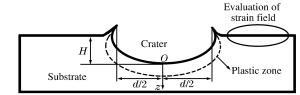
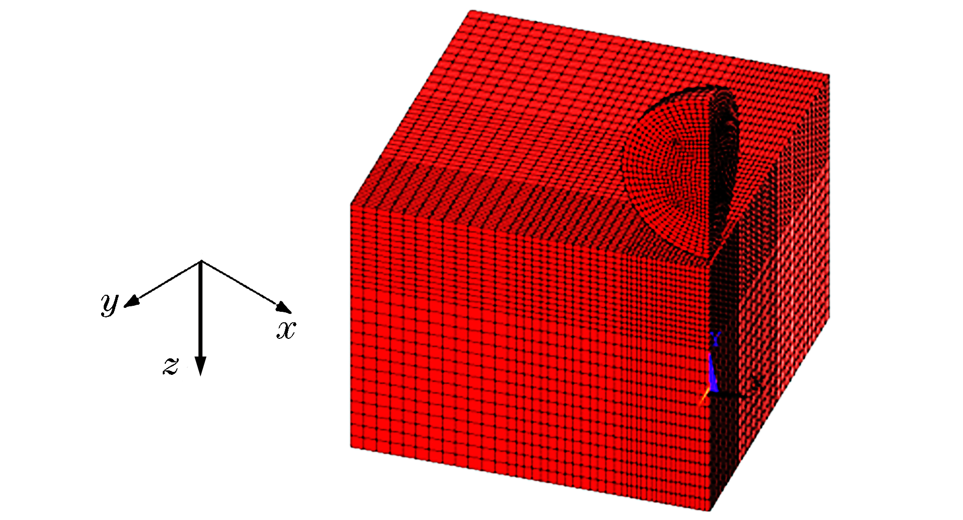
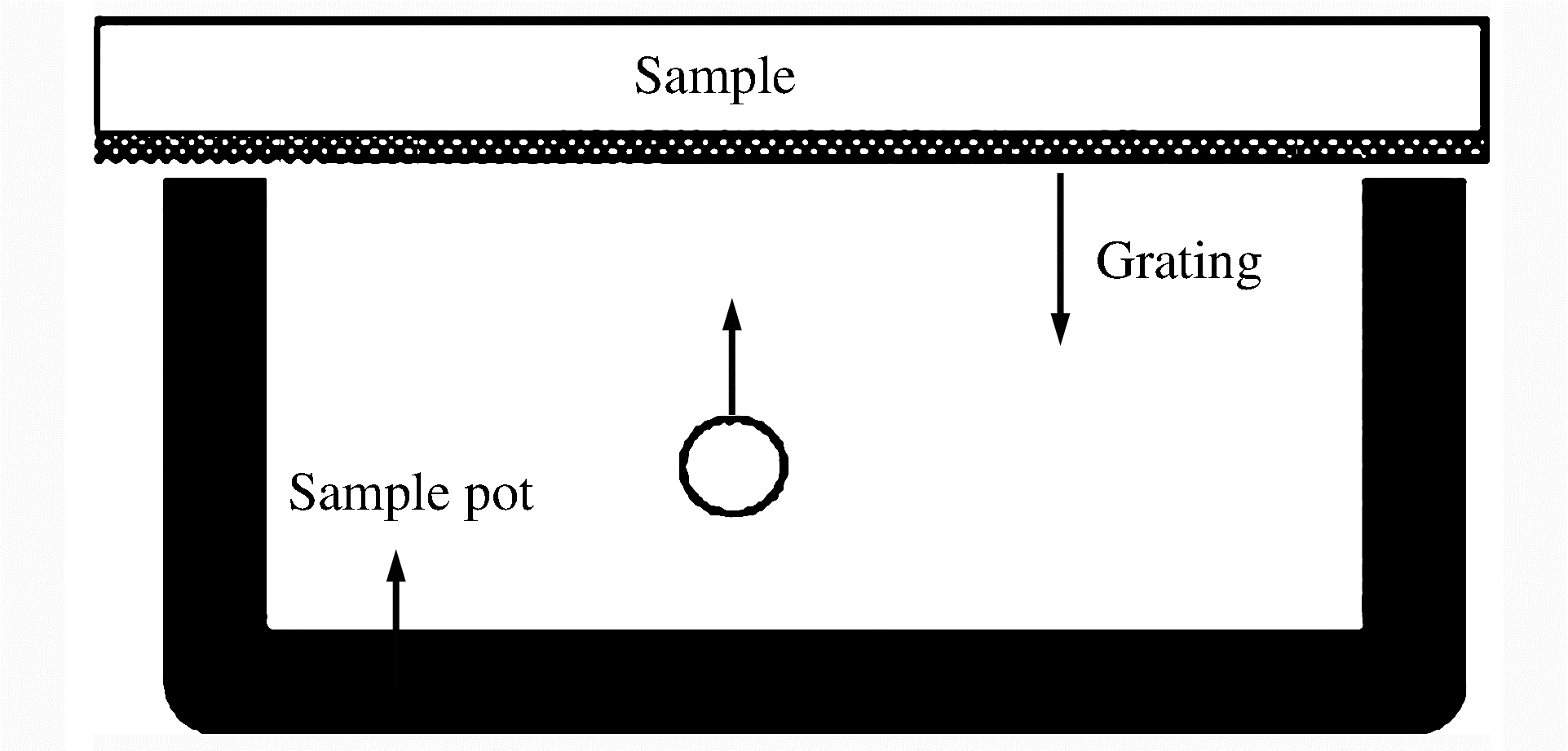
图 4 弹丸撞击试件的变形示意图
Figure 4. Schematic diagram of deformation after shot impact substrate

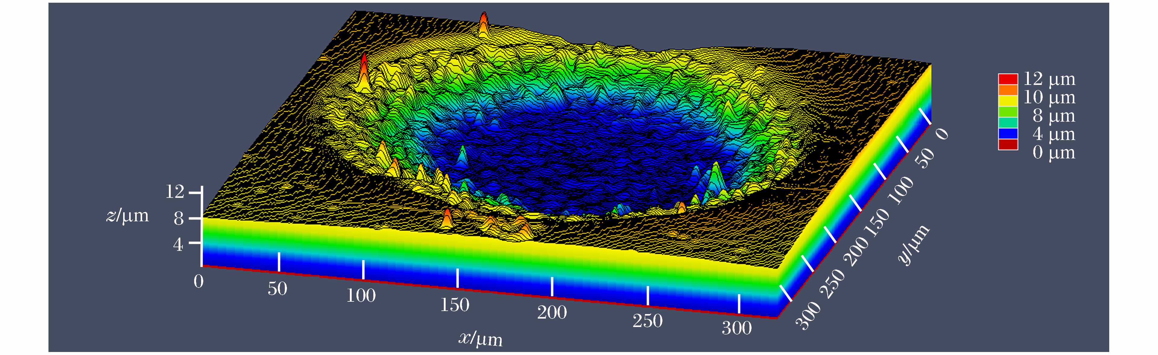
图 5 频率为50 Hz时弹坑的三维形貌图
Figure 5. Three-dimensional topography of crater at frequency of 50 Hz
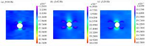
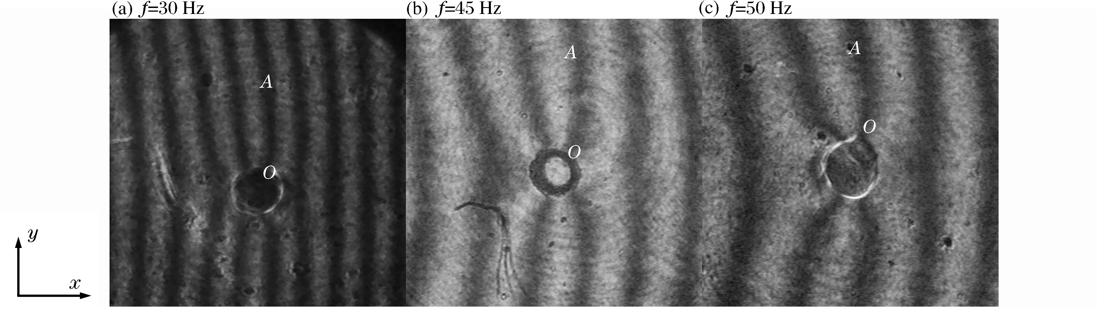
图 10 不同频率时U场应变分布
Figure 10. Strain distribution in U-displacement at different frequencies
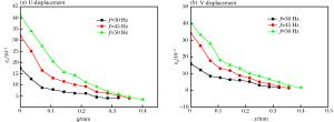
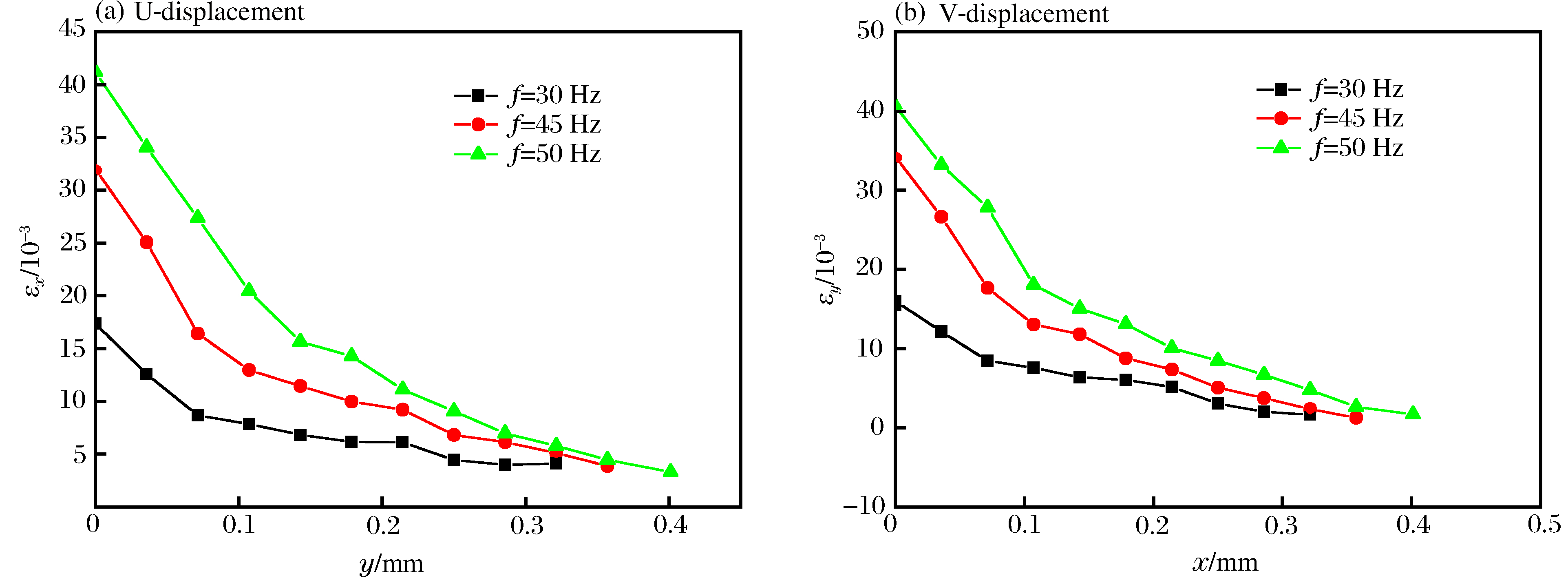
图 11 不同频率下U场和V场的应变分布规律
Figure 11. Strain distribution regularities in U-displacement and V-displacement at different frequencies

图 12 弹丸垂直撞击和倾斜撞击时相同频率下U场云纹图
Figure 12. Contour maps in U-displacement at same frequency under vertical or oblique impact
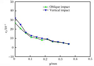
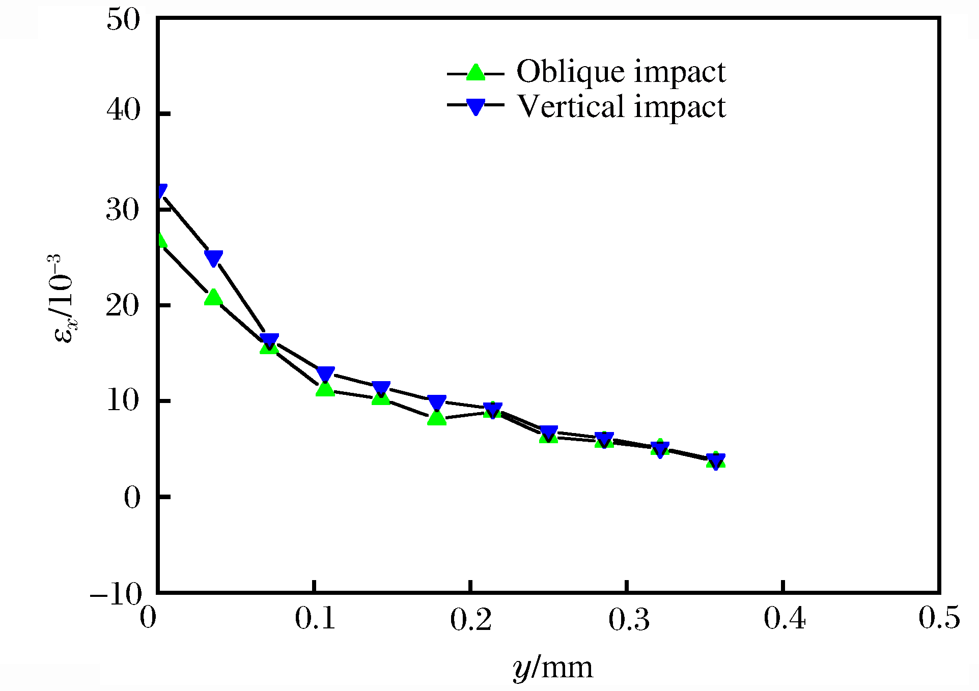
图 13 相同撞击频率不同撞击角度时应变变化规律
Figure 13. Strain regularities at the same impact frequency and the different impact angles

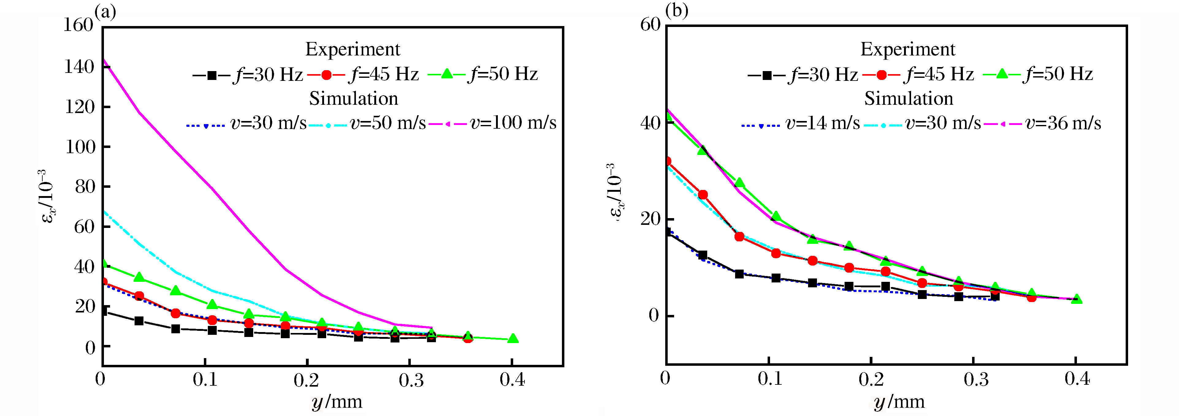
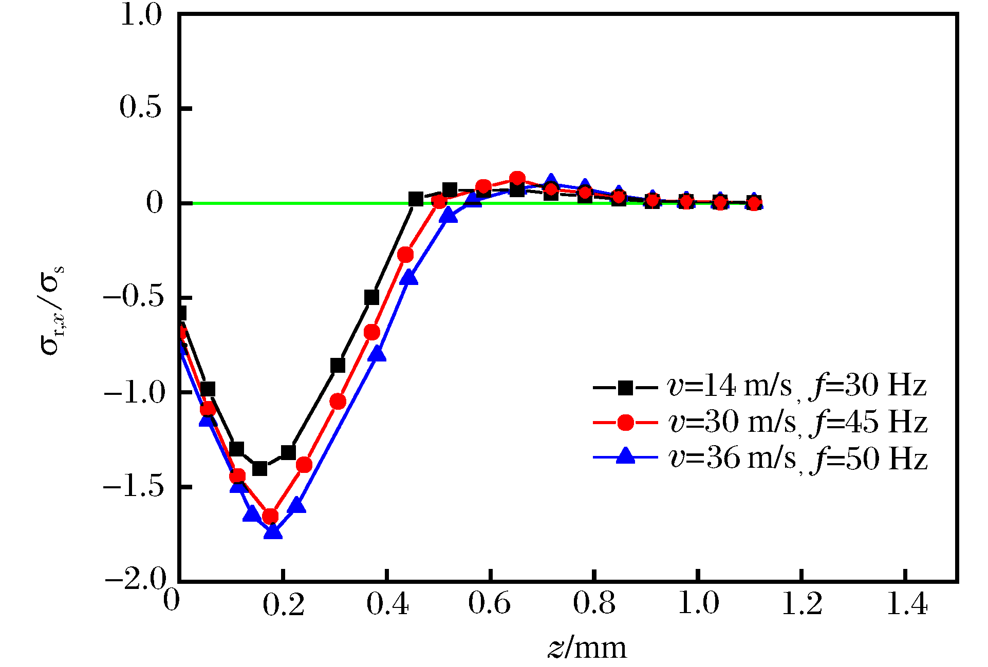
图 14 x方向应变沿y方向变化规律
Figure 14. Change of strain regularity in x direction along the y direction
-
[1] Marteau J, Bigerelle M, Mazeran P E, et al. Relation between roughness and processing conditions of AISI 316L stainless steel treated by ultrasonic shot peening[J]. Tribology International, 2015, 82:319-329. doi: 10.1016/j.triboint.2014.07.013 [2] Ganesh B K C, Sha W, Ramanaiah N, et al. Effect of shotpeening on sliding wear and tensile behavior of titanium implant alloys[J]. Materials and Design, 2014, 56(4):480-486. http://www.wanfangdata.com.cn/details/detail.do?_type=perio&id=d2428b4f6fa62767ff66efd3f8f0b4cd [3] Benedetti M, Fontanari V, Santus C, et al. Notch fatigue behavior of shot peened high-strength aluminium alloys: Experiments and predictions using a critical distance method[J]. International Journal of Fatigue, 2010, 32(10):1600-1611. doi: 10.1016/j.ijfatigue.2010.02.012 [4] 栾伟玲, 涂善东.喷丸表面改性技术的研究进展[J].中国机械工程, 2005, 16(15):1405-1049. doi: 10.3321/j.issn:1004-132X.2005.15.023Luan Weiling, Tu Shandong. Recent trends on surface modification technology of shot peening[J]. China Mechanical Engineering, 2005, 16(15):1405-1049. doi: 10.3321/j.issn:1004-132X.2005.15.023 [5] Al-Obaid Y F. Shot peening mechanics: experimental and theoretical analysis[J]. Mechanics of Materials, 1995, 19(2/3):251-260. http://d.old.wanfangdata.com.cn/NSTLQK/NSTL_QKJJ0211961014/ [6] Menig R, Pintschovius L, Schulze V, et al. Depth profiles of macro residual stresses in thin shot peened steel plates determined by X-ray and neutron diffraction[J]. Scripta Materialia, 2001, 45(8):977-983. doi: 10.1016/S1359-6462(01)01063-6 [7] Xing Y M, Lu J. An experimental study of residual stress induced by ultrasonic shot peening[J]. Journal of Materials Processing Technology, 2004, 152(1):56-61. http://www.wanfangdata.com.cn/details/detail.do?_type=perio&id=f4518f2da0effa1755be7dca1bc56be4 [8] 张洪伟, 张以都, 吴琼.喷丸强化过程及冲击效应的数值模拟[J].金属学报, 2010, 46(1):111-117. http://www.wanfangdata.com.cn/details/detail.do?_type=perio&id=CAS201303040000302556Zhang Hongwei, Zhang Yidu, Wu Qiong. Numerical simulations of shot-peening process and impact effect[J]. Acta Metallurgica Sinica, 2010, 46(1):111-117. http://www.wanfangdata.com.cn/details/detail.do?_type=perio&id=CAS201303040000302556 [9] Taehyung K, Hyungyil L, Hong C H, et al. Effects of Rayleigh damping, friction and rate-dependency on 3D residual stress simulation of angled shot peening[J]. Materials and Design, 2013, 46(4):26-37. http://www.wanfangdata.com.cn/details/detail.do?_type=perio&id=1ab77b975ca1cdf02a33903920abb275 [10] Taehyung K, Hyungyil L, Minsoo K, et al. A 3D FE model for evaluation of peening residual stress under angled multi-shot impacts[J]. Surface & Coatings Technology, 2012, 206(19/20):3981-3988. http://www.sciencedirect.com/science/article/pii/S0257897212002599 [11] Sheng X F, Xia Q X, Cheng X Q, et al. Residual stress field induced by shot peening based on random-shots for 7075 aluminum alloy[J]. Transactions of Nonferrous Metals Society of China, 2012, 22:261-267. doi: 10.1016/S1003-6326(12)61717-8 [12] Mylonas G I, Labeas G. Numerical modeling of shot peening process and corresponding produces: Residual stress, surface roughness and cold work prediction[J]. Surface & Coatings Technology, 2011, 205(19):4480-4494. http://www.sciencedirect.com/science/article/pii/S0257897211002696 [13] Watanabe M, Kishimoto S, Xing Y M, et al. Evaluation of strain field around impacted particles by applying electron Moiré method[J]. Journal of Thermal Spray Technology, 2007, 16(5):940-946. doi: 10.1007/s11666-007-9129-1 [14] Schiffner K, Helling C D. Simulation of residual stresses by shot peening[J]. Computers & Structures, 1999, 72(1/2/3):329-340. http://www.sciencedirect.com/science/article/pii/S0045794999000127 [15] Meguid S A, Shagal G, Stranart J C, et al. Three-dimensional dynamic finite element analysis of shot-peening induced residual stresses[J]. Finite Elements in Analysis and Design, 1999, 31(3):179-191. doi: 10.1016/S0168-874X(98)00057-2 [16] Meo M, Vignjevic R. Finite element analysis of residual stress induced by shot peening process[J]. Advances in Engineering Software, 2003, 34(03):569-575. doi: 10.1016-j.clon.2010.02.005/ [17] Umbrello D, Saoubi R M, Outeiro J C. The influence of Johnson-Cook material constants on finite element simulation of machining of AISI 316L steel[J]. International Journal of Machine Tools & Manufacture, 2007, 47(3/4):462-470. http://www.wanfangdata.com.cn/details/detail.do?_type=perio&id=da2b63f7ce1c3f04be8bf54f29588b1e [18] Wang J M, Liu F H, Yu F, et al. Shot peening simulation based on SPH method[J]. The International Journal of Advanced Manufacturing Technology, 2011, 56(5/6/7/8):571-578. http://d.old.wanfangdata.com.cn/Periodical/sdgydxxb201006013 -

 下载:
下载:


计量
- 文章访问数: 4575
- HTML全文浏览量: 1742
- PDF下载量: 480
- 被引次数: 0