


Coupled loading simulation for combined pulse fracturing and the sensitivity analysis of different propellant ratios
-
摘要: 基于组合脉冲压裂物理过程,以三种燃速火药柱串联、中心管同步点燃方式,结合火药爆燃加载、压挡液柱运动、射孔孔眼泄流、裂缝起裂、高压气体裂缝内流动及裂缝扩展等子模型,组建多级爆燃压裂耦合模拟模型。并据此分析不同配比火药组合爆燃压裂时,井底压力变化及裂缝延伸情况。结果表明:不同燃速火药串联组合可实现一级火药快速爆燃,瞬间达到多方向射孔孔眼起裂压力,二、三级火药持续长时间燃烧维持高压以充分延伸裂缝的目的;在确定一级快速火药和总火药用量后,井底爆燃压力加载速率和各方向破裂压力均随第三级燃速火药质量比重的增加而呈现降低趋势,但变化不明显;而不同方向裂缝最终延伸长度对二、三级燃速火药的配比具有较强敏感性;在以多方向裂缝安全起裂为目标、设定一级燃速火药后,合理配比三种火药比单一配比高-中速、高-低速火药,可更有效地延长爆燃压裂过程的井底有效持压时间,从而可大幅扩展火药用量上限,提高爆燃压裂裂缝延伸规模。Abstract: In the present study, based on the physical process of combined pulse fracturing, we proposed a model for the coupling of the whole process of multi-pulse conflagration fracturing using different combinations of the multi-level pulse propellant conflagration loading model, the pressurized liquid column movement model, the perforation discharge model, the fracture initiation and the fracture dynamic extension model. Furthermore, we analyzed the wellbore pressure changes and the fractures propagation under single and combined propellants at different ratios. The calculated results demonstrated that fast deflagration fracturing could be initiated using combinations of the first-phase propellants with different burning rates and the multi-directional wellbore pressure was reached at once; a longer burning time of the propellant might be held to maintain the high pressure for the full extension of the fracture, using the second-and the third-phase propellants; when the amount of the first-phase propellants and the total amount of the propellants were determined, the deflagration loading rate and the multi-directional fracture initiation pressure tended to decrease slightly as the lowest burning rate of the third-phrase propellant's proportion rose up, though not obviously; the eventual extension lengths of the fracture in different directions were, however, very sensitive to the proportion of the second-and third-phase propellants. These results improved our understanding of the coupling mechanism of the combined pulse fracturing, and might be used to optimize the mass ratio of propellants.
-

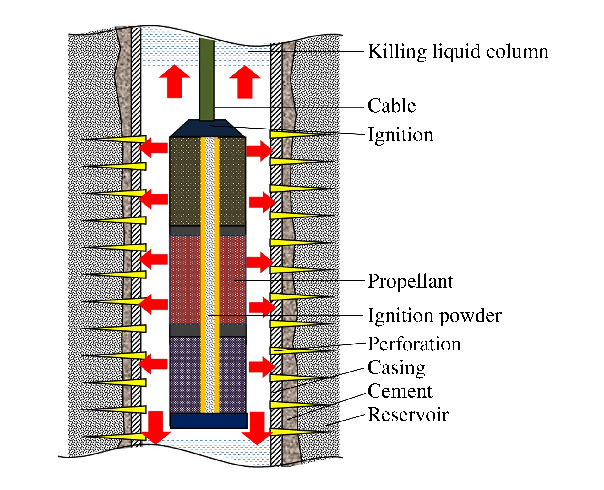
图 1 多级燃速火药压裂井下压裂弹结构示意图
Figure 1. Schematic model of combined pulse fracturing structure
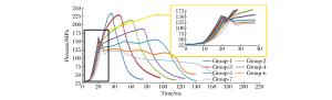
图 2 不同火药用量组合下燃爆加载曲线
Figure 2. Loading curves in different combinations of three kinds of propellants
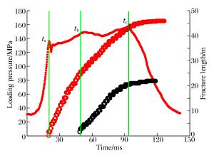
图 3 第5组燃爆过程爆燃压力与裂缝动态扩展曲线
Figure 3. Deflagration pressure and dynamic expansion of fractures of the fifth combination
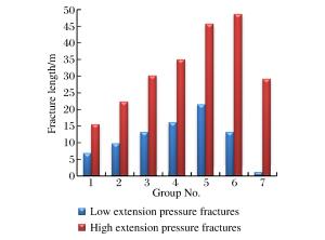
图 4 各组合方案下裂缝最终延伸长度
Figure 4. Final lengths of fractures of all the propellants combinations
表 1 不同压力条件下三级燃速火药燃速方程
Table 1. Burning rate equations of three kinds of propellants under different pressures
高燃速火药 中燃速火药 低燃速火药 p/MPa 燃速方程 p/MPa 燃速方程 p/MPa 燃速方程 0~15 u=4.448 7p0.654 9 0~11 u=3.392 2p0.463 4 0~20 u=2.756 3p0.259 7 15~45 u=1.891 2p0.984 0 11~45 u=1.107 8p0.933 0 20~65 u=0.223 9p1.097 5 45~120 u=37.09p0.196 3 45~100 u=15.466p0.220 6 65~110 u=5.007 3p0.355 5 >120 u=0.215 2p1.248 4 >100 u=0.544 5p0.939 8 >110 u=0.053 7p1.313 5 注:燃速方程中,u为燃速(km/s),p为压力(MPa);高、中、低3种燃速火药的密度分别为1.86、1.77、1.73 g/cm3,燃烧能分别为1 216、1 100.8、1 002.1 kJ。  下载: 导出CSV
表 2 不同燃速火药用量组合
Table 2. Combinations of three kinds of propellants
组 火药用量/kg 高燃速火药 中燃速火药 低燃速火药 1 30 60 0 2 30 50 10 3 30 40 20 4 30 30 30 5 30 20 40 6 30 10 50 7 30 0 60
下载: 导出CSV
-
[1] 蒲春生, 孙志宇, 王香增, 等.多级脉冲气体加载压裂技术[J].石油勘探与开发, 2008, 35(5):636-639. http://industry.wanfangdata.com.cn/dl/Detail/Periodical?id=Periodical_syktykf200805018PU Chunsheng, SUN Zhiyu, WANG Xiangzeng, et al. Technique of multi-pulse gas load fracturing[J]. Petroleum Exploration and Development, 2008, 35(5):636-639. http://industry.wanfangdata.com.cn/dl/Detail/Periodical?id=Periodical_syktykf200805018 [2] BOSCAN J, ALMANZA E, FOLSE K, et al. Propellant perforation breakdown technique: eastern Venezuela field application[C]//SPE International Improved Oil Recovery Conference in Asia Pacific. Kuala Lumpur, Malaysia, 2003. [3] RAMIREZ J, BARRERA J, ROMERO R. Propellant assisted perforating in high-pressure and temperature wells at Campo Bosque in Northern Monagas State[C]//SPE Annual Technical Conference and Exhibition. New Orleans, Louisiana, 2001. [4] GUO B, SHAN J, FENG Y. Productivity of blast-fractured wells in liquid-rich shale gas formations[J]. Journal of Natural Gas Science and Engineering, 2014(18):360-367. https://www.sciencedirect.com/science/article/pii/S1875510014000791 [5] ZHU W C, GAI D, WEI C H, et al. High-pressure air blasting experiments on concrete and implications for enhanced coal gas drainage[J]. Journal of Natural Gas Science and Engineering, 2016, 36:1253-1263. doi: 10.1016/j.jngse.2016.03.047 [6] GRUBELICH M C, KING D, KNUDSEN S, et al. An overview of a high energy stimulation technique for geothermal applications[C]//Proceedings World Geothermal Congress. Melbourne Australia, 2015. [7] 吴飞鹏. 高能气体压裂过程动力学模型与工艺技术优化决策研究[D]. 青岛: 中国石油大学(华东), 2009: 13-20. [8] 吴飞鹏, 蒲春生, 吴波.燃爆压裂中压挡液柱运动规律的动力学模型[J].爆炸与冲击, 2010, 30(6):633-641. doi: 10.11883/1001-1455(2010)06-0633-08WU Feipeng, PU Chunsheng, WU Bo. A dynamic model of the pressurized liquid column movement[J]. Explosion and Shock Waves, 2010, 30(6):633-641. doi: 10.11883/1001-1455(2010)06-0633-08 [9] CUDERMAN J F. Tailored-pulse fracturing in cased and perforated bore-holes[C]//Tailored-Pulse Fracturing in Cased and Perforated Bore-Holes. Louisville, Kentucky, 1986. [10] 吴飞鹏, 蒲春生, 陈德春, 等.燃爆强加载条件下油井破裂压力试验研究[J].岩石力学与工程学报, 2009, 28(增刊2):3430-3434. http://industry.wanfangdata.com.cn/dl/Detail/Periodical?id=Periodical_yslxygcxb2009z2020WU Feipeng, PU Chunsheng, CHEN Dechun. Test study of oil well breakdown pressure under blasting loading[J]. Chinese Journal of Rock Mechanics and Engineering, 2009, 28(suppl 2):3430-3434. http://industry.wanfangdata.com.cn/dl/Detail/Periodical?id=Periodical_yslxygcxb2009z2020 [11] 卢文波, 陶振宇.爆生气体驱动的裂纹扩展速度研究[J].爆炸与冲击, 1994, 14(3):264-267. http://www.bzycj.cn/CN/abstract/abstract10636.shtmlLU Wenbo, TAO Zhenyu. A study of fracture propagation velocity driven by gas of explosion on products[J]. Explosion and Shock Waves, 1994, 14(3):264-267. http://www.bzycj.cn/CN/abstract/abstract10636.shtml [12] NILSON R H, PROFFER W J, DUFF R E. Modeling of gas driven fractures induced by propellant combustion within a borehole[J]. International Journal of Rock Mechanics and Mining Sciences & Geomechanics Abstracts, 1985, 22(1):3-19. https://www.sciencedirect.com/science/article/pii/0148906285925896 [13] GEERTSMA J. Estimating the coefficient of inertial resistance in fluid flow through porous media[J]. Society of Petroleum Engineers Journal, 1974(10):445-450. http://industry.wanfangdata.com.cn/dl/Detail/ExternalResource?id=syktykf201405013%5e29 [14] GEORGE E, ZACHARIAS A, ELEFTHERIOS L. Effect the fracture process zone in directed crack propagation in borehole blasting[C]//Rock Mechanics in Petroleum Engineering. Delft, Netherlands, 1994. [15] WU F, PU C, CHEN D, et al. Coupling simulation of multistage pulse conflagration compression fracturing[J]. Petroleum Exploration and Development, 2014, 41(5):663-670. doi: 10.1016/S1876-3804(14)60079-3 -


计量
- 文章访问数: 4661
- HTML全文浏览量: 1270
- PDF下载量: 153
- 被引次数: 0