


Different failure modes during the high-velocity penetration on the ship plate structure through material point method
-
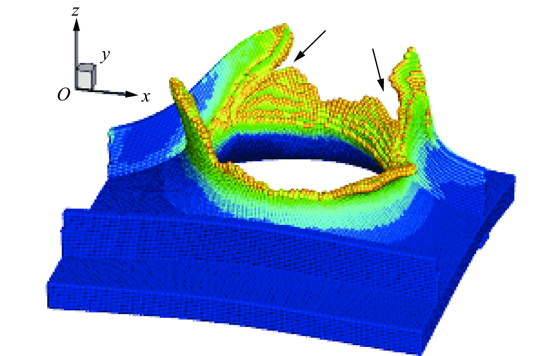
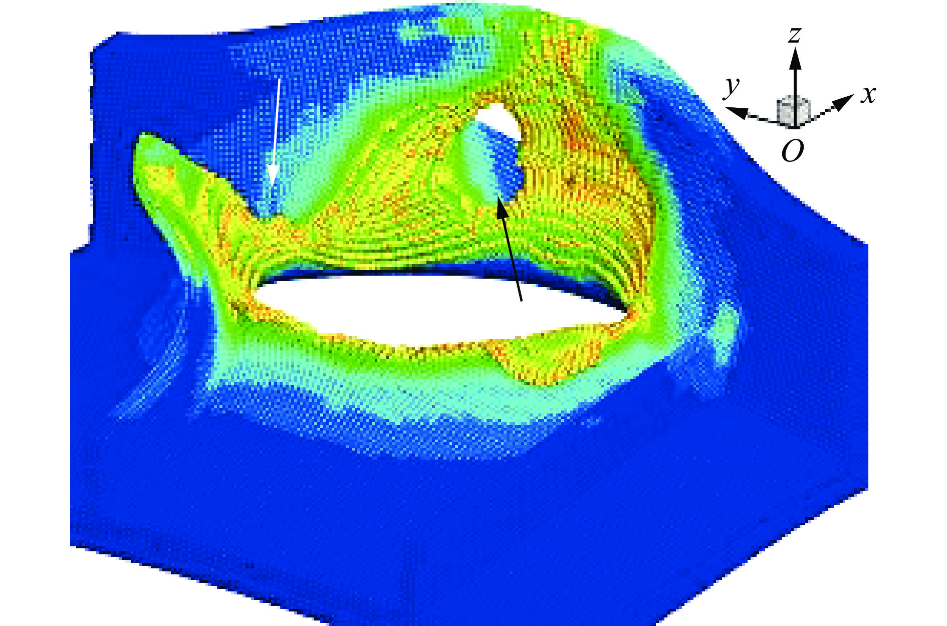
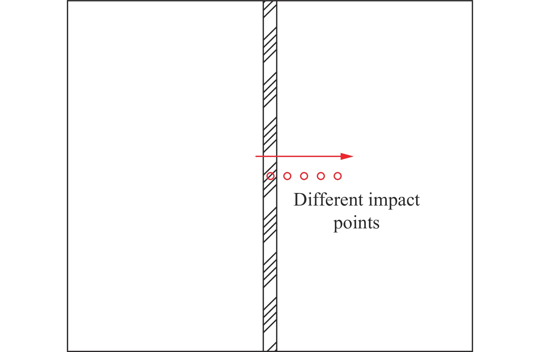
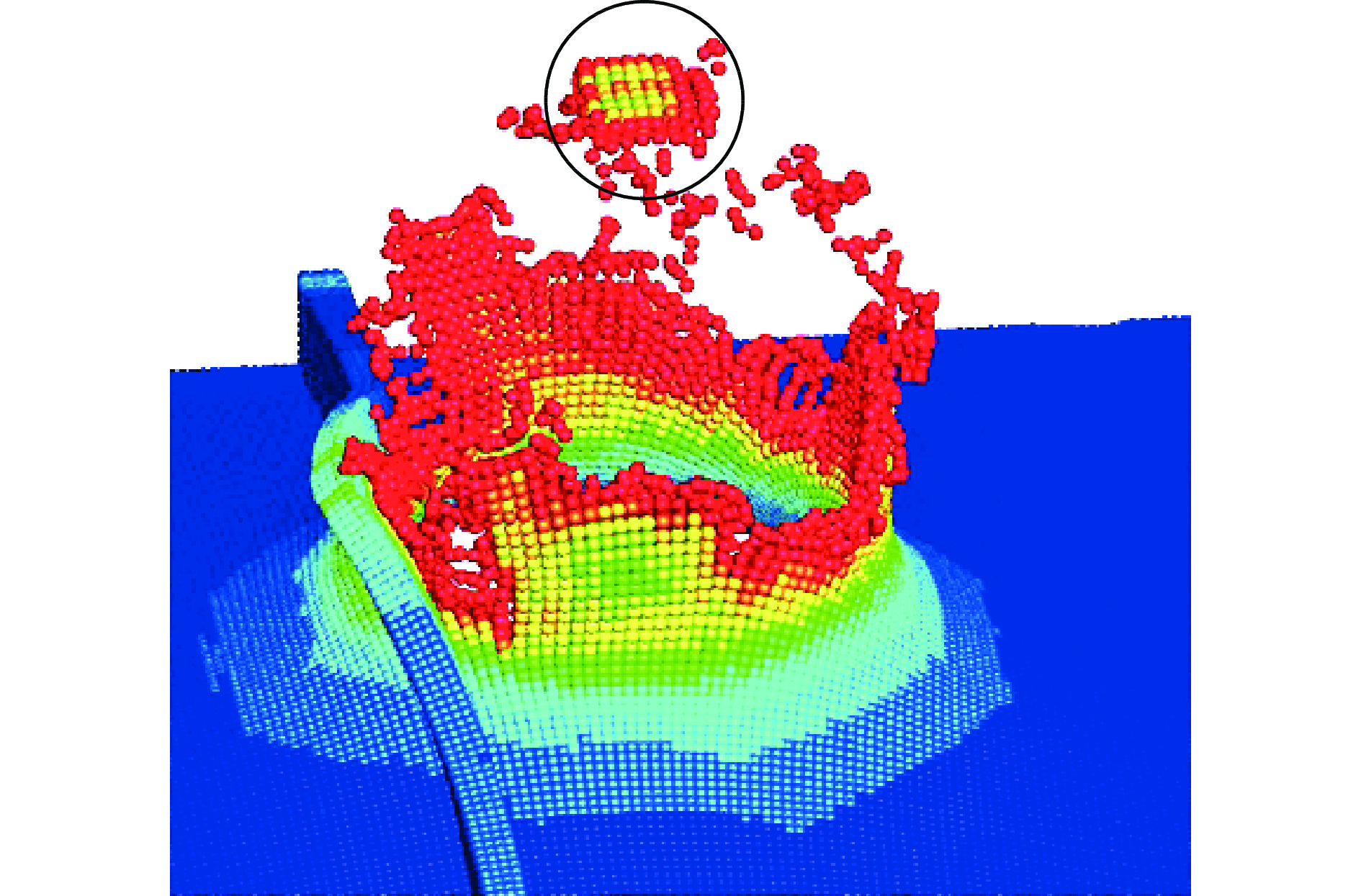
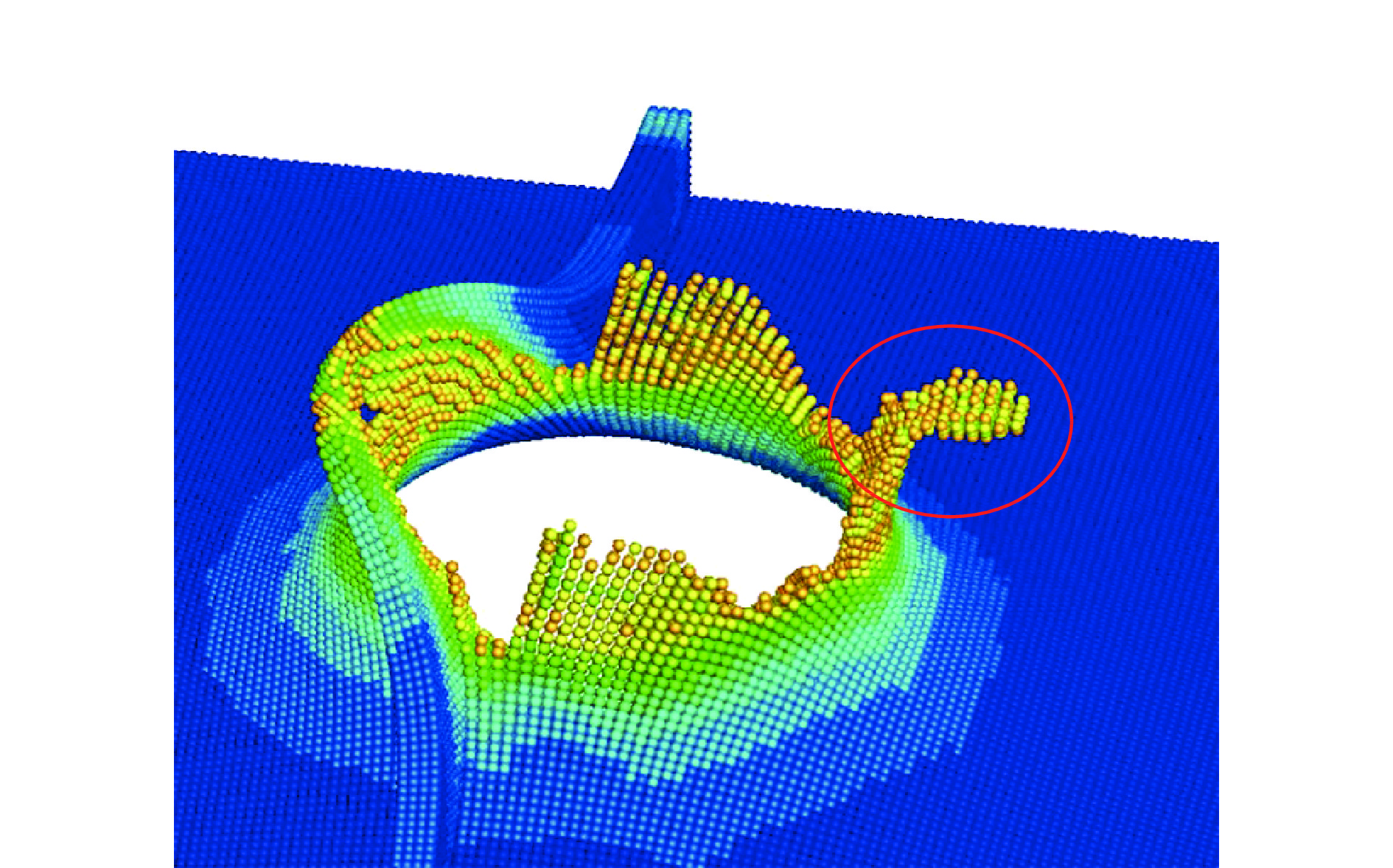
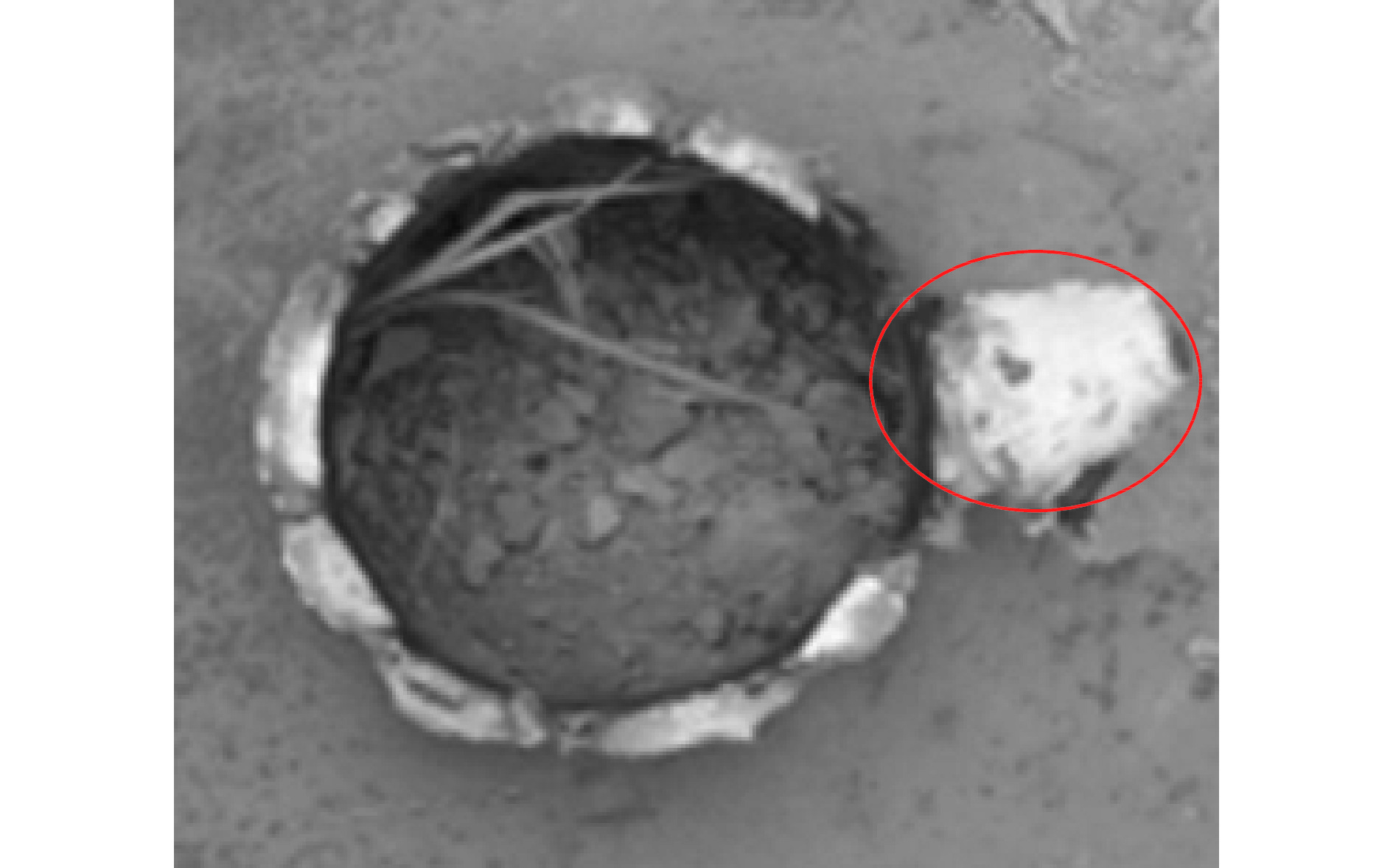
摘要: 本文通过数值模拟的方法研究了截卵型弹体冲击下921A钢板的毁伤模式。 跟以往试验进行对比,发现数值结果与实验结果吻合良好。 在3种不同工况下,剩余速度与实验结果吻合良好,误差小于5%。随着弹着点位置的变化,加筋板的失效模式发生变化。击中靶板中心时,加强筋发生撕裂,目标板在左右两侧产生对称的花瓣型破坏模式。 随着弹着点位置的偏移,加强筋的撕裂程度逐渐减小,最后仅仅发生塑性应变。并且目标板上的破坏不再对称,左侧板的动态响应从花瓣破坏变为小面积断裂,最后仅保留塑性变形。右侧板始终产生花瓣型失效模式,但花瓣的数量和形式始终在变化。结果表明,物质点法可以很好地应用,并为今后舰船穿透研究提供参考。Abstract: In this paper, the numerical simulation of 921A steel target under the impact of truncated-ogive projectile is studied. The numerical results agrees well with the experimental results. Under three different conditions, the residual velocity is in good agreement with the experimental results, and the error is less than 5%. With the change of the impact point position, the failure modes of the stiffened plate target plate is described in detail. First, the stiffener tears and the failure by symmetrical petalling occurs in target plate on the both left and right side. With the change of the impact point position, the tearing degree of stiffener decreases gradually, and the stiffener deforms plastically only. The petals on target plate are no longer symmetrical, and the dynamic response of the left target plate transforms from petalling failure to small break, and only plastic deformation remains at last. The right target plate always produced petalling failure mode, but the number and form of petals always change. The results show that material point method can be applied well, and it can provide some reference data for the future research of ship penetration.
-
Key words:
- projectile penetration /
- impact point /
- failure mode /
- material point method
-
图 4 剩余速度随3种不同冲击速度的变化情况
Figure 4. Variation of residual velocity with three different impact velocities
泊松比 A/MPa B/MPa n C m $ \lambda $ smax/MPa tmax/MPa 0.35 685 760 0.587 0.015 1.027 1 685 342  下载: 导出CSV
表 2 剩余速度的数值和实验结果
Table 2. Numerical values and experimental results of residual velocity
工况 冲击速度/
(m·s−1)弹着点位置 实验剩余速度/
(m·s−1)物质点剩余速度/
(m·s−1)距大筋/
mm距小筋/
mm1 617.7 0.0 31.0 574.9 571.7 2 606.5 − − 583.8 560.1 3 567.7 55.0 52.0 526.8 515.0
下载: 导出CSV
表 3 数值和实验无量纲数结果对比
Table 3. Comparison of numerical and experimental dimensionless number results
工况 无量纲数 $ \dfrac{{{v_r}}}{{{v_i}}} $ 误差/% 实验 数值 1 0.931 0.926 0.5 2 0.963 0.923 4.2 3 0.928 0.908 2.2
下载: 导出CSV
-
[1] 张中国, 黄风雷, 段卓平, 等. 弹体侵彻带加强筋结构靶的实验研究 [J]. 爆炸与冲击, 2004, 24(5): 431–436.ZHANG Z G, HUANG F L, DUAN Z P, et al. The experimental research for projectile penetrating the structural target with rebar [J]. Explosion and Shock Waves, 2004, 24(5): 431–436. [2] 段卓平. 半穿甲弹丸对加筋靶板侵彻的终点弹道的实验和理论研究 [J]. 爆炸与冲击, 2005, 25(6): 547–552.DUAN Z P. The experimental and theoretical research for end-point trajectory of warhead penetrating ribbings structural target [J]. Explosion and Shock Waves, 2005, 25(6): 547–552. [3] 段卓平, 张中国, 李金柱, 等. 半穿甲战斗部对加筋靶板和均质靶板垂直侵彻的实验研究 [J]. 弹箭与制导学报, 2005, 25(2): 148–150;157. DOI: 10.3969/j.issn.1673-9728.2005.02.051.DUAN Z P, ZHANG Z G, LI J Z, et al. The experimental research for warhead vertically penetrating homogeneous and ribbings structural target [J]. Journal of Projectiles, Rockets, Missiles and Guidance, 2005, 25(2): 148–150;157. DOI: 10.3969/j.issn.1673-9728.2005.02.051. [4] 姚熊亮, 吴子奇, 王治, 等. 战斗部对舰船靶标侵彻毁伤效能研究 [J]. 哈尔滨工程大学学报, 2019, 40(1): 141–145. DOI: 10.11990/jheu.201808002.YAO X L, WU Z Q, WANG Z, et al. Study on damage effectiveness of warhead on ship target [J]. Journal of Harbin Engineering University, 2019, 40(1): 141–145. DOI: 10.11990/jheu.201808002. [5] 宋卫东, 宁建国, 张中国, 等. 多层加筋靶板的侵彻模型与等效方法 [J]. 弹道学报, 2004, 16(3): 54–59. DOI: 10.3969/j.issn.1004-499X.2004.03.010.SONG W D, NING J G, ZHANG Z G, et al. Penetration model and equivalence method of multi-layered stiffener plates [J]. Journal of Ballistics, 2004, 16(3): 54–59. DOI: 10.3969/j.issn.1004-499X.2004.03.010. [6] 展婷变, 吕淑芳, 黄德雨. 截卵形弹体正侵彻加强筋结构靶的理论分析 [J]. 弹道学报, 2012, 24(1): 52–57. DOI: 10.3969/j.issn.1004-499X.2012.01.011.ZHAN T B, LV S F, HUANG D Y. Theoretical analysis on normal penetration of truncated oval-nosed projectile into stiffened plate [J]. Journal of Ballistics, 2012, 24(1): 52–57. DOI: 10.3969/j.issn.1004-499X.2012.01.011. [7] 巨圆圆, 张庆明. 尖卵形弹丸侵彻加筋薄靶剩余速度的理论分析 [J]. 兵工学报, 2015, 36(S1): 126–130.JU Y Y, ZHANG Q M. Theoretical analysis on residual velocity of oval-nosed projectile penetrating into stiffened thin plate [J]. Acta Armamentarii, 2015, 36(S1): 126–130. [8] 陈长海, 朱锡, 侯海量. 加筋板架抗动能穿甲的等效防护厚度研究 [J]. 海军工程大学学报, 2010, 22(1): 35–42. DOI: 10.7495/j.issn.1009-3486.2010.01.007.CHEN C H, ZHU X, HOU H L. Equivalent protection thickness of stiffened plate against kinetic piercing [J]. Journal of Naval University of Engineering, 2010, 22(1): 35–42. DOI: 10.7495/j.issn.1009-3486.2010.01.007. [9] 张宁. 均质靶板和加筋靶板抗弹性能的数值模拟研究 [J]. 兵器装备工程学报, 2016, 37(2): 30–33. DOI: 10.11809/scbgxb2016.02.008.ZHANG N. Numerical simulation for effect of homogeneous and stiffened plates on resisting projectile penetration [J]. Journal of Ordnance Equipment Engineering, 2016, 37(2): 30–33. DOI: 10.11809/scbgxb2016.02.008. [10] MA S, ZHANG X, QIU X M. Comparison study of MPM and SPH in modeling hypervelocity impact problems [J]. International Journal of Impact Engineering, 2009, 36(2): 272–282. [11] LIAN Y P, ZHANG X, LIU Y. Coupling of finite element method with material point method by local multi-mesh contact method [J]. Computer Methods in Applied Mechanics and Engineering, 2011, 200(47−48): 3482–3494. [12] 秦业志, 姚熊亮, 王志凯, 等. 基于物质点法的弹体侵彻靶板破甲特性数值模拟 [J]. 中国舰船研究, 2018, 13(3): 118–124. DOI: 10.19693/j.issn.1673-3185.01173.QIN Y Z, YAO X L, WANG Z K, et al. Numerical simulation of projectile penetration into steel plate based on material point method [J]. Chinese Journal of Ship Research, 2018, 13(3): 118–124. DOI: 10.19693/j.issn.1673-3185.01173. [13] 谢桂兰, 陈飞, 龚曙光, 等. 基于物质点法不同头部形状弹体侵彻动靶过程的仿真研究 [J]. 应用力学学报, 2019, 36(3): 573–579;758. DOI: 10.11776/cjam.36.03.D019.XIE G L, CHEN F, LONG S G, et al. Numerical simulation on the projectile with different nose shapes penetrating moving target based on material point method [J]. Chinese Journal of Applied Mechanics, 2019, 36(3): 573–579;758. DOI: 10.11776/cjam.36.03.D019. [14] 李依潇, 王生捷. 使用新型物态方程的超高速碰撞物质点法模拟 [J]. 爆炸与冲击, 2019, 39(10): 145–151. DOI: 10.11883/bzycj-2018-0261.LI Y X, WANG S J. Simulation of hypervelocity impact by the material point method coupled with a new equation of state [J]. Explosion and Shock Waves, 2019, 39(10): 145–151. DOI: 10.11883/bzycj-2018-0261. [15] WANG Y, YANG N, ZHANG W, et al. Material point method and its application in different failure modes of grillage structure under penetration [J]. Ships and Offshore Structures, 2020, 15(9): 998–1010. DOI: 10.1080/17445302.2019.1699326. [16] 张雄, 廉艳平, 刘岩, 等. 物质点法[M]. 第1版. 北京: 清华大学出版社, 2013: 38−65. [17] 杨鹏飞. 局部化破坏问题的物质点法研究[D]. 北京: 清华大学, 2013: 71−78. [18] 郑勇刚, 顾元宪, 陈震. 薄膜破坏过程数值模拟的MPM方法 [J]. 力学学报, 2006, 38(3): 347–355. DOI: 10.3321/j.issn:0459-1879.2006.03.009.ZHENG Y G, GU Y X, CHEN Z. Numerical simulation of thin film failure with MPM [J]. Chinese Journal of Theoretical Applied Mechanics, 2006, 38(3): 347–355. DOI: 10.3321/j.issn:0459-1879.2006.03.009. -


图(30) / 表(3)
计量
- 文章访问数: 777
- HTML全文浏览量: 424
- PDF下载量: 111
- 被引次数: 0