Experimental study on detonation propagation in industrial scale pipelines used in petrochemical plants
-
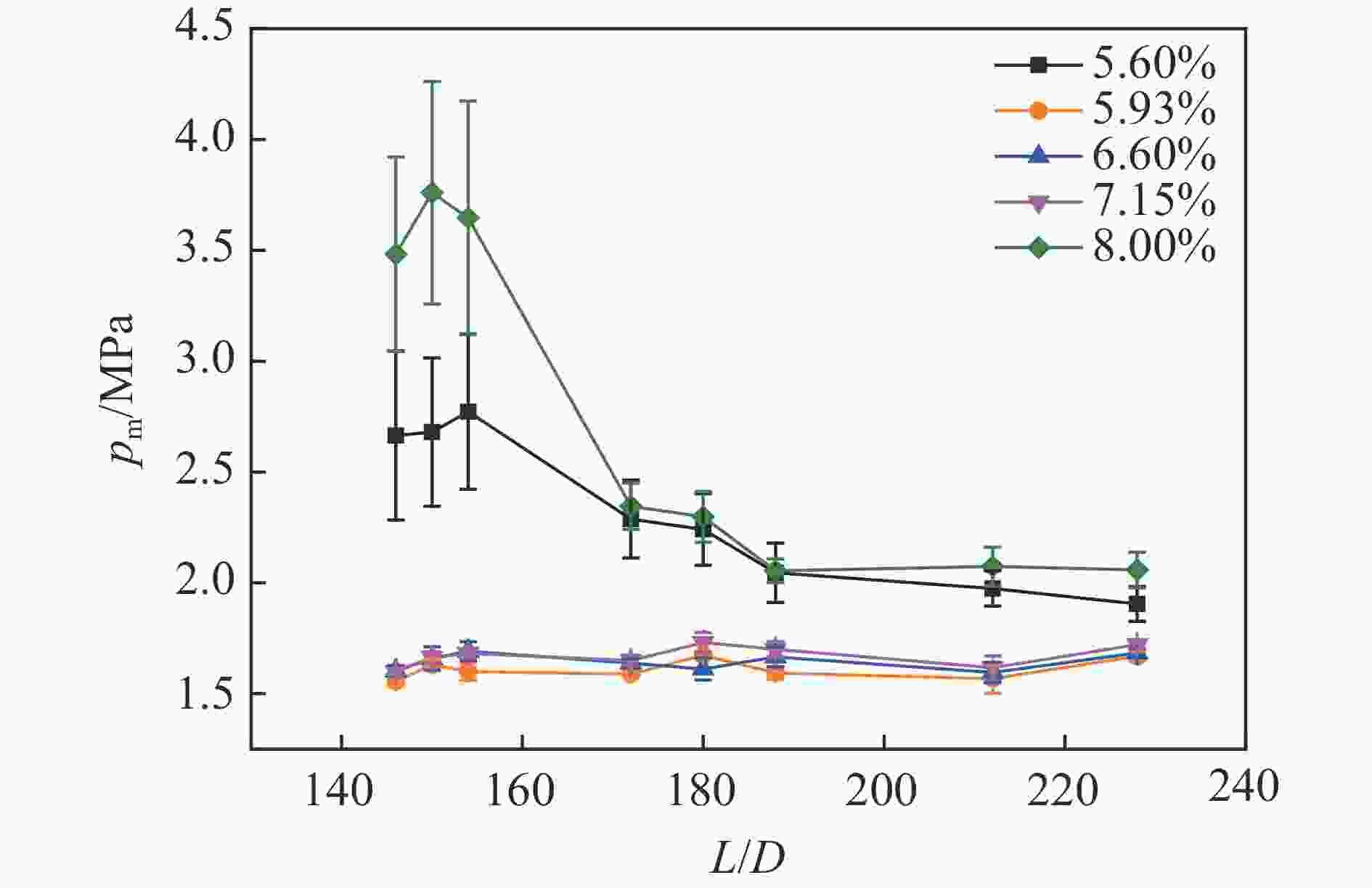
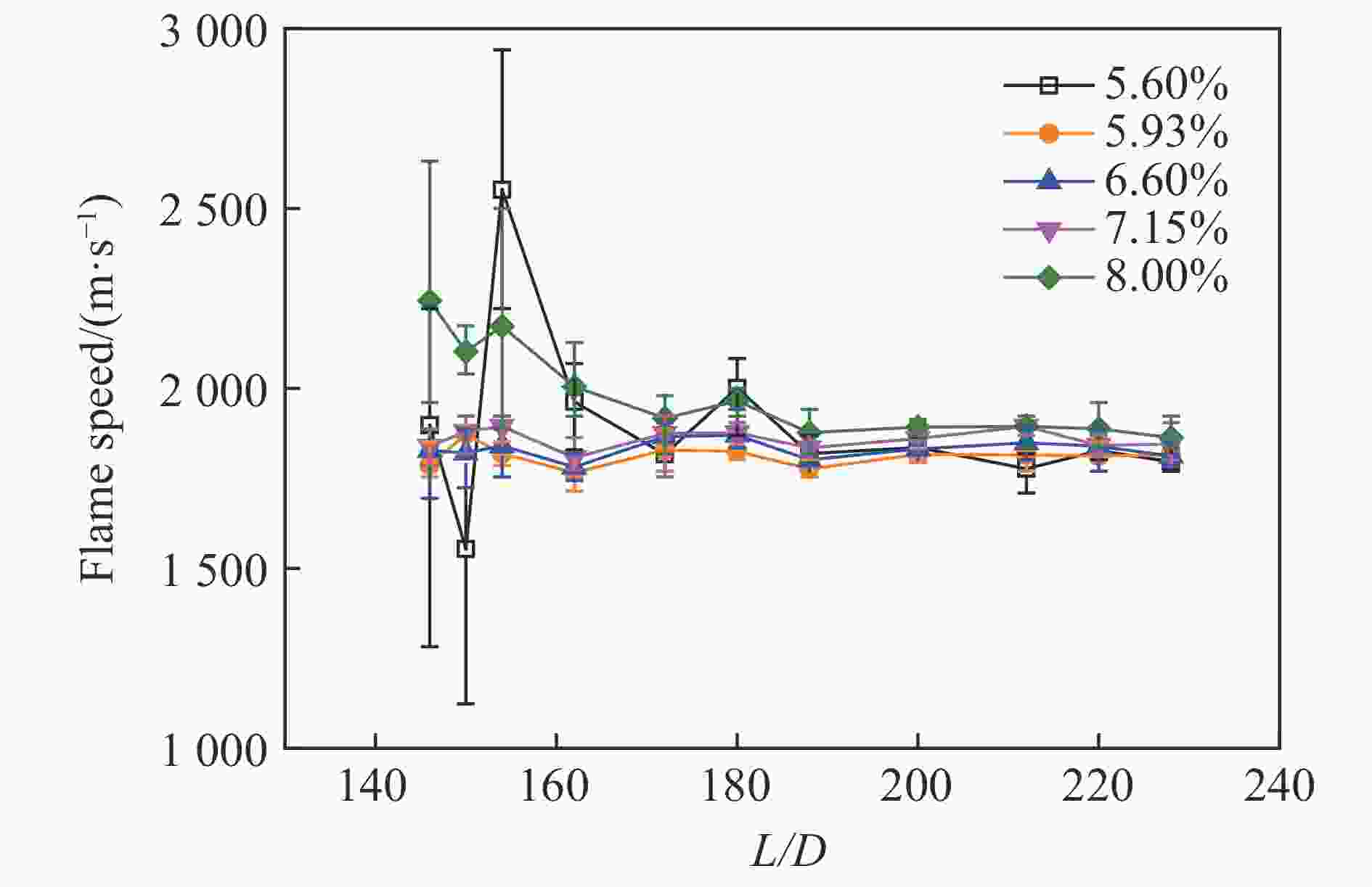
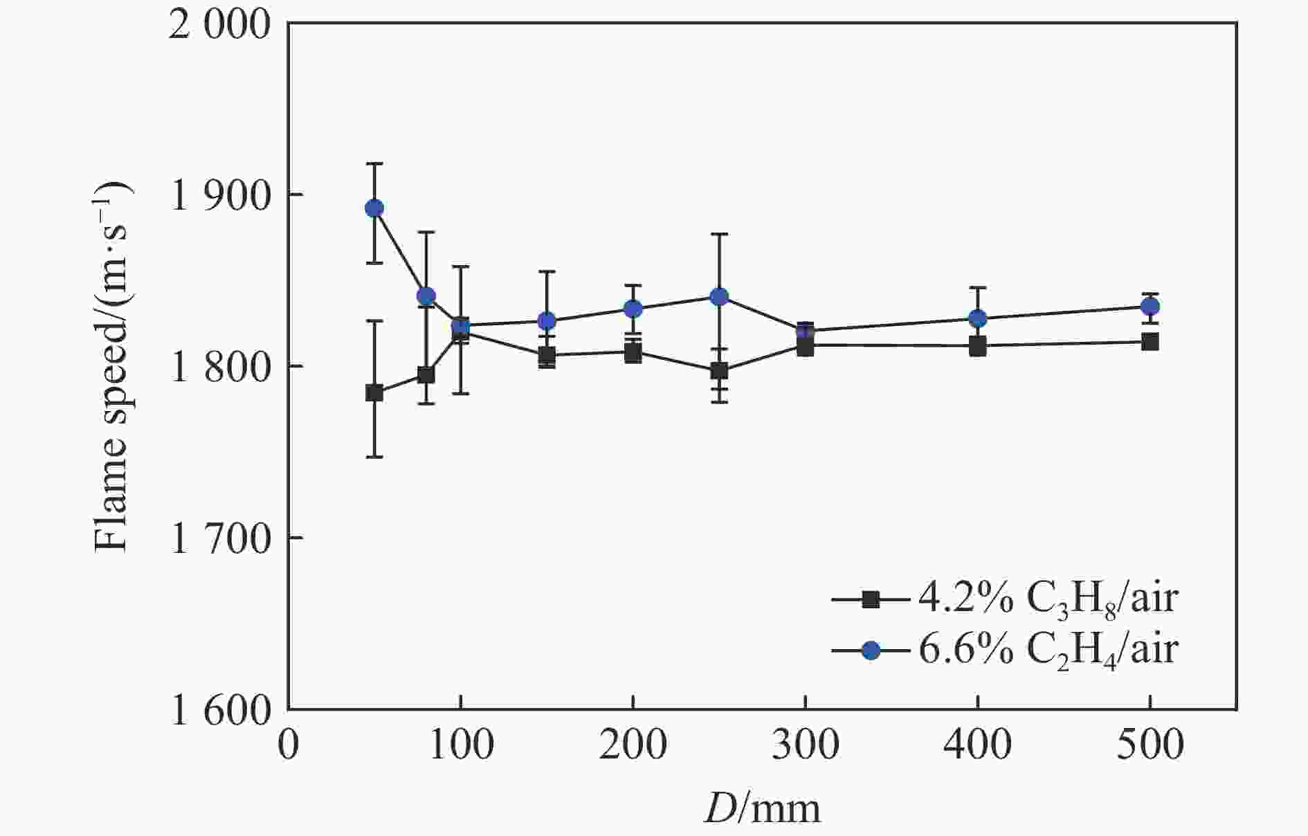
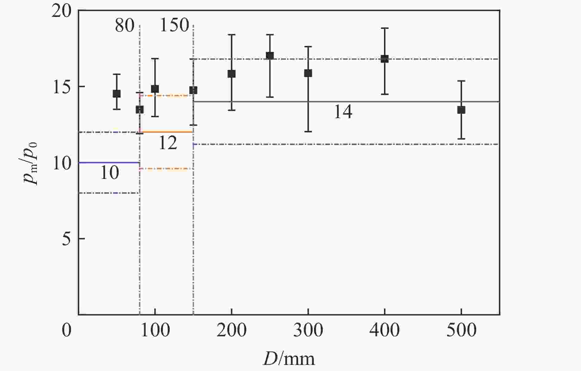
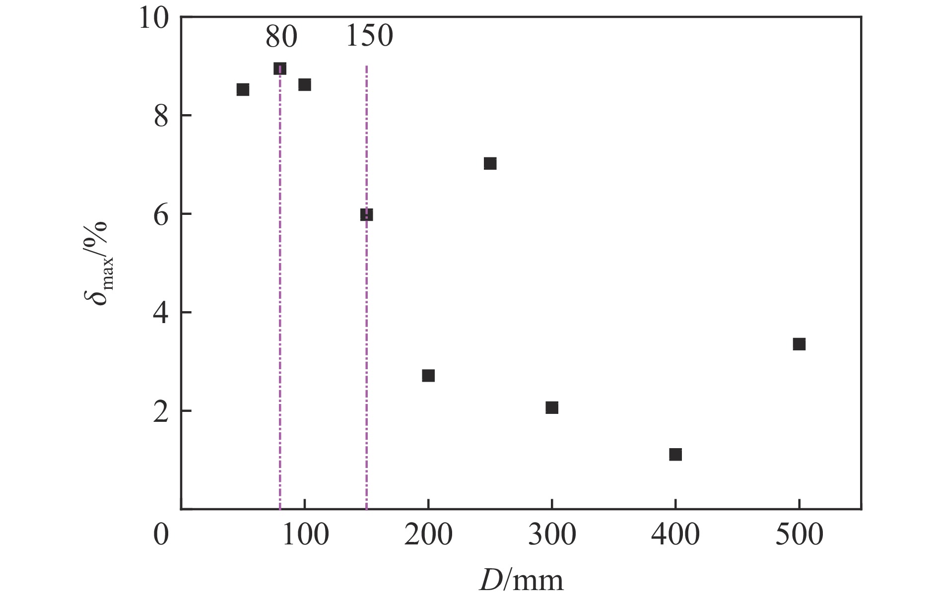
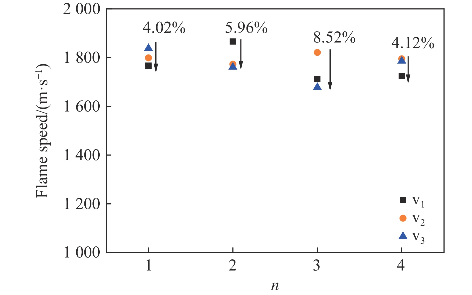
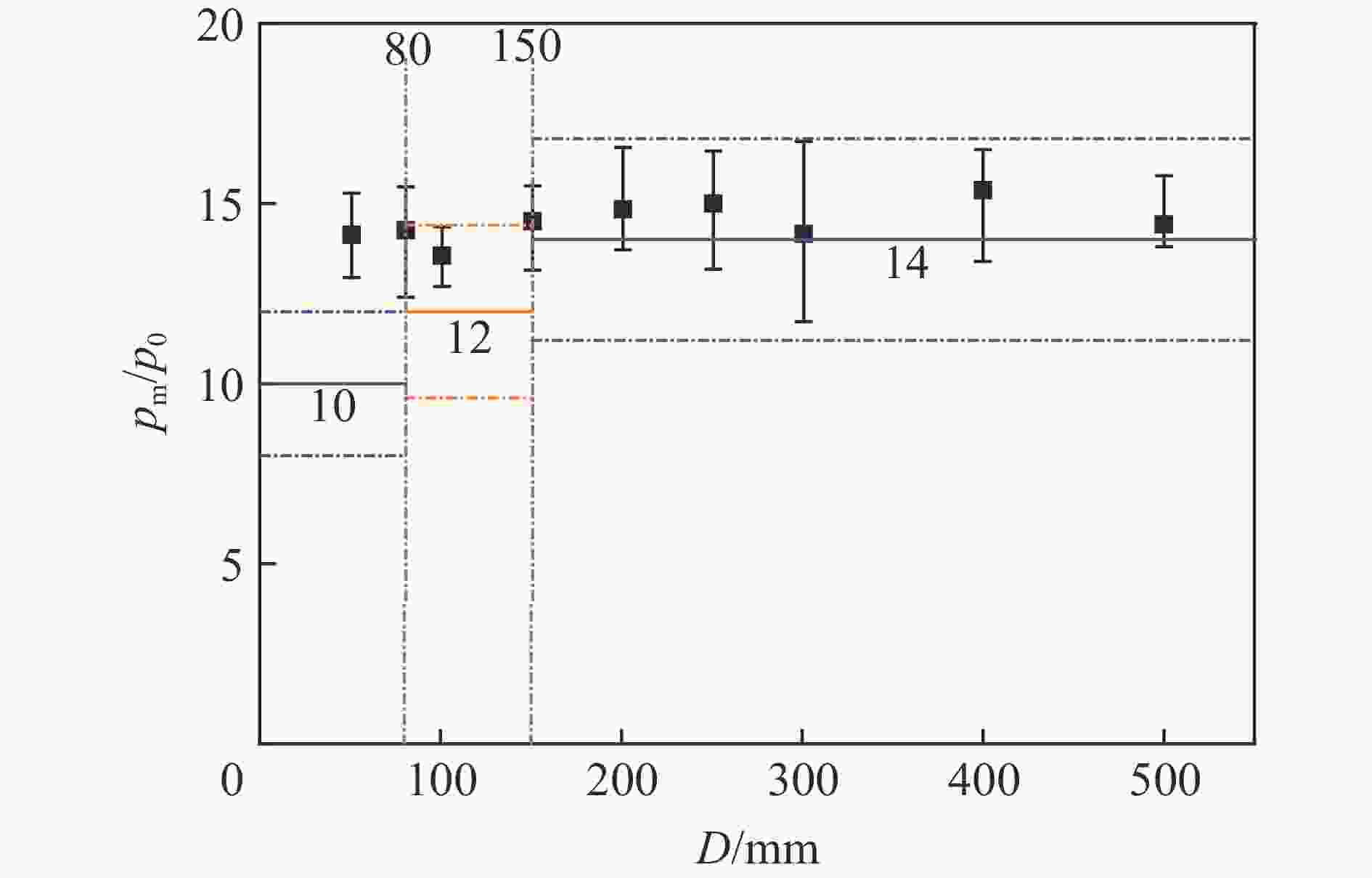
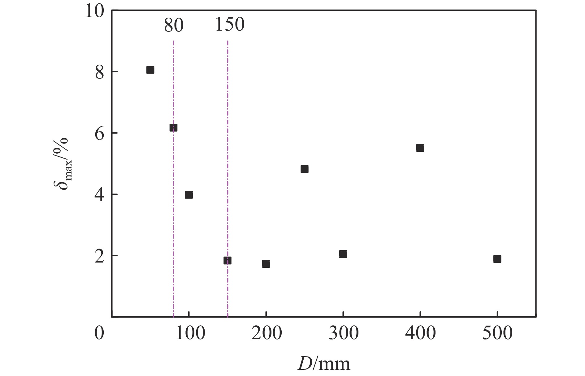
摘要: 针对石化装置罐区大口径、长距离管道内火焰传播缺乏系统研究的问题,设计搭建了DN50~DN500工业尺度管道火焰传播实验装置,并开展了丙烷/空气、乙烯/空气等可燃气体在不同管径下的实验研究。实验结果表明:可燃气体积分数对火焰传播及爆轰有一定影响,当接近化学计量浓度时,爆轰加速距离更短,更易形成稳态爆轰,而当可燃气混合气为贫燃或富燃状况时,爆轰加速距离则会增长;火焰爆轰传播速度、爆轰压力与管道管径基本无关,受可燃气种类影响更大;对应体积分数为6.6%的乙烯/空气和体积分数为4.2%的丙烷/空气混合气体,爆轰压力分别是初始压力的15.17和14.47倍,DN150以下管径内的爆轰压力远高于ISO16852标准给出的参考值。罐区连通管道阻火器选型安装时,应结合安装位置选用合适的阻火器。Abstract: Based on the lack of systematic research on flame propagation in large-diameter and long-distance pipelines in the tank area of petrochemical plants, an experimental device for flame propagation in DN50-DN500 industrial-scale pipelines was designed and built. In this paper, effects of concentration of gas mixture for propagation characteristics of steady gaseous detonation waves in ethylene-air mixtures with DN50 pipeline were studied experimentally. The volume concentration of gas mixture was 5.6%, 5.93%, 6.6%, 7.15%, 8.0% ethylene in air. Homogeneous C2H4/air (6.6%) and C3H8/air (4.2%) mixtures were used with 9 kinds of pipelines which were from DN50 to DN500 to study the effects of pipeline diameter for propagation characteristics of steady gaseous detonation. The experimental results show that the concentration of combustible gas has an effect on flame propagation and detonation. The detonation runup distance is short and steady detonation is more likely to be formed when it is close to chemical equivalent concentration, when the combustible mixture is poorer or richer, the steady detonation will need more runup distance. The detonation flame speed and pressure are more affected by the type of combustible gas instead of pipe diameter. The detonation pressure of the mixture of 6.6% C2H4/air and the mixture of 4.2% C3H8/air is 15.17 and 14.47 times of the initial pressure, respectively, which is different from the reference value given by the ISO16852 standard where the ratio pm/p0 (the average value of the detonation pressure to initial pressure) increases with pipe diameter. The detonation pressure of pipeline below DN150 is far higher than the reference value which is 10 and 12. It’s suggested that in the design of pipelines and selection and installation of flame arresters for connecting pipelines in the tank areas, detonation pressure requires careful consideration and appropriate arresters should be selected in combination with the installation position.
-
Key words:
- gaseous detonation /
- flame propagation /
- industrial scale /
- pipeline
-
表 1 各实验管道长度
Table 1. Length of each experimental pipeline
管径/mm 长度/m 管径/mm 长度/m 50 15 250 55 80 24 300 60 100 25 400 84 150 36 500 110 200 48 表 2 50 mm管道实验装置火焰速度传感器布置位置
Table 2. Location of flame speed sensors in 50-mm-pipeline experimental apparatus
传感器 位置/D 传感器 位置/D 传感器 位置/D v1 144 v5 168 v9 208 v2 148 v6 176 v10 216 v3 152 v7 184 v11 224 v4 156 v8 192 v12 232 表 3 50 mm管道实验装置火焰压力传感器布置位置
Table 3. Location of flame pressure sensors in 50-mm-pipeline experimental apparatus
传感器 位置/D 传感器 位置/D p1 146 p5 180 p2 150 p6 188 p3 154 p7 212 p4 172 p8 228 表 4 ISO16852标准的
$p_{\rm m}/p_0 $ 参考值Table 4.
$p_{\rm m}/p_0 $ given by ISO16852介质 D≤80 mm 80 mm<D
≤150 mm150 mm<D
<1 000 mmD≥1000 mm C3H8/空气 10±2 12±2.4 14±2.8 16±3.2 C2H4/空气 10±2 12±2.4 14±2.8 16±3.2 -
[1] 王鹏, 白永忠, 党文义, 等. 储罐VOCs安全收集零排放装置: CN110143376B [P]. 2018-02-13. [2] PROUST C. Gas flame acceleration in long ducts [J]. Journal of Loss Prevention in the Process Industries, 2015, 36: 387–393. DOI: 10.1016/j.jlp.2015.04.001. [3] WANG L Q, MA H H, SHEN Z W, et al. Effects of bluff bodies on the propagation behaviors of gaseous detonation [J]. Combustion & Flame, 2019, 201: 118–128. [4] CICCARELLI G, DOROFEEV S. Flame acceleration and transition to detonation in ducts [J]. Progress in Energy and Combustion Science, 2008, 34(4): 499–550. DOI: 10.1016/j.pecs.2007.11.002. [5] 周凯元, 李宗芬. 丙烷-空气爆燃波的火焰面在直管道中的加速运动 [J]. 爆炸与冲击, 2000, 20(2): 137–142.ZHOU K Y, LI Z F. Flame front acceleration of propane-air deflagration in straight tubes [J]. Explosion and shock waves., 2000, 20(2): 137–142. [6] CICCARELLI G, WANG Z, LU J, et al. Effect of orifice plate spacing on detonation propagation [J]. Journal of Loss Prevention in the Process Industries, 2017, 49(9): 739–744. DOI: 10.1016/j.jlp.2017.03.014. [7] 周宁, 王文秀, 张国文, 等. 障碍物对丙烷-空气爆炸火焰加速的影响 [J]. 爆炸与冲击, 2018, 38(5): 1106–1114. DOI: 10.11883/bzycj-2017-0049.ZHOU N, WANG W X, ZHANG G W, et al. Effect of obstacles on flame acceleration of propane-air explosion [J]. Explosion and Shock Waves., 2018, 38(5): 1106–1114. DOI: 10.11883/bzycj-2017-0049. [8] ZHANG B. The influence of wall roughness on detonation limits in hydrogen–oxygen mixture [J]. Combustion and Flame, 2016, 169(7): 333–339. DOI: 10.1016/j.combustflame.2016.05.003. [9] 司荣军. 管道内瓦斯爆炸传播试验研究 [J]. 煤炭科学技术, 2009, 37(2): 47–50.SI R J. Test and research on gas explosion transmission in pipeline [J]. Coal Science and Technology, 2009, 37(2): 47–50. [10] ZURAIJI A A, ZANGANEH J, MOGHTADERI B. Application of flame arrester in mitigation of explosion and flame deflagration of ventilation air methane [J]. Fuel, 2019, 257(1): 115985. DOI: 10.1016/j.fuel.2019.115985. [11] LIU Q M, BAI C H, LI X D, et al. Coal dust/air explosions in a large-scale tube [J]. Fuel, 2010, 89(2): 329–335. DOI: 10.1016/j.fuel.2009.07.010. [12] 蒋新生, 谢威, 赵亚东, 等. 不同长径比的狭长管道油气爆炸实验 [J]. 油气储运, 2020, 39(8): 879–884.JIANG X S, XIE W, ZHAO Y D, et al. Experimental study on gasoline air mixture explosion using long-narrow pipes with different aspect ratios of oil storage and transportation engineering [J]. Oil & Gas Storage and Transportation., 2020, 39(8): 879–884. [13] 孙少辰, 毕明树, 刘刚, 等. 爆轰火焰在管道阻火器内的传播与淬熄特征 [J]. 化工学报, 2016, 67(5): 2176–2184.SUN S C, BI M S, LIU G, et al. Detonation flame propagation and quenching characteristics in crimped-ribbon flame arrester [J]. Journal of Chemical Industry and Engineering, 2016, 67(5): 2176–2184. [14] ISO/TC 21Equipment for fire protection and fire fighting: ISO16852:2016 [S/OL]. 2016. [15] 夏昌敬, 周凯元, 沈兆武. 初始条件影响气体非稳态爆轰波在弯管中传播特性的实验研究 [J]. 中国科学技术大学学报, 2004(1): 95–100.XIA C J, ZHOU K Y, SHEN Z W. Experimental study on effects of initial conditions for propagation characteristics of unsteady gaseous detonation in channels with a bend [J]. Journal of University of Science and Technology of China., 2004(1): 95–100. [16] BSI Standards. Guide for the selection, application and use of flame arresters: CEN16793 [S]. 2016. [17] KERSTEN C, FORSTER H. Investigation of deflagrations and detonations in pipes and flame arresters by high-speed framing [J]. Journal of Loss Prevention in the Process Industries, 2004, 17: 43–50. DOI: 10.1016/j.jlp.2003.09.004. -


 下载:
下载:
