


Experimental and numerical studies on penetration resistance of armor steel/UHPC composite targets
-
摘要: 装甲钢/超高性能混凝土(UHPC)复合防护结构在重点工程中抵抗弹体的高速侵彻作用具有广泛的应用前景。为评估该复合结构的抗侵彻性能,对两种复合靶体开展侵彻试验与数值模拟研究。首先,开展了12发30 mm口径30CrMnSiNi2A弹体372~646 m/s速度侵彻复合靶试验。随后通过一系列静动态力学性能试验标定装甲钢材料的本构模型参数,并建立三维有限元模型对上述试验开展数值模拟分析。通过对比试验和数值模拟得到的弹体侵彻深度、残余弹体长度和装甲钢板的失效模式,验证了装甲钢本构模型参数的可靠性。进一步基于弹道效益系数对复合靶抗侵彻性能进行了定量评估。最后,确定了不同装甲钢板厚度复合靶体的临界贯穿速度,并对弹体侵彻复合靶的弹、靶失效模式进行了讨论。Abstract: Armor steel/ultra-high performance concrete (UHPC) composite structures have a wide application prospect in the protective structures against the high-speed projectile penetration. Aiming to evaluate the penetration resistance of the composite targets, both field tests and numerical simulations were carried out on two types of armor steel/UHPC composite targets. Firstly, twelve 30mm-caliber 30CrMnSiNi2A steel projectile penetration tests on different armor steel/UHPC composite targets were conducted with the striking velocities varying from 372 m/s to 646 m/s. Compared to the UHPC target, the armor/UHPC composite targets present high penetration resistance and low areal density. The test results show that the penetration resistance of the NP500/UHPC composite target with an armor steel thickness of 5 mm can be increased by 35.7% compared to that of the NP450/UHPC composite target. Besides, a series of static and dynamic mechanical tests for armor steels were conducted to calibrate the parameters of the constitutive model. Then, 3D finite element models were established and the corresponding numerical simulations were carried out. The parameters of the constitutive model of the armor steel were validated by comparing the experimental penetration depth, residual projectile length and failure mode of the armor steel plate with the numerical results. Furthermore, the impact resistance of the armor steel/UHPC composite targets was discussed quantitatively via the ballistic efficiency factor. For the cases in this study, the composite target with 8mm thick NP500 armor steel exhibits the best ballistic performance. Finally, the critical perforation velocities of two types of armor steels with different thicknesses in the composite targets were determined. The failure modes of the projectile and target were further discussed. As the strength and hardness of the armor steel increase, the failure mode changes from shear plugging failure to ductile hole expansion failure.
-
图 6 弹体、装甲钢和UHPC靶体损伤
Figure 6. Damage of projectiles, armor steel plates and UHPC targets

图 8 冲击速度(v0)对侵彻深度(h)的影响
Figure 8. Influence of striking velocity (v0) on penetration depth (h)
图 10 室温单轴拉伸真实应力-应变曲线
Figure 10. Uniaxial tensile true stress-strain curves at room temperature
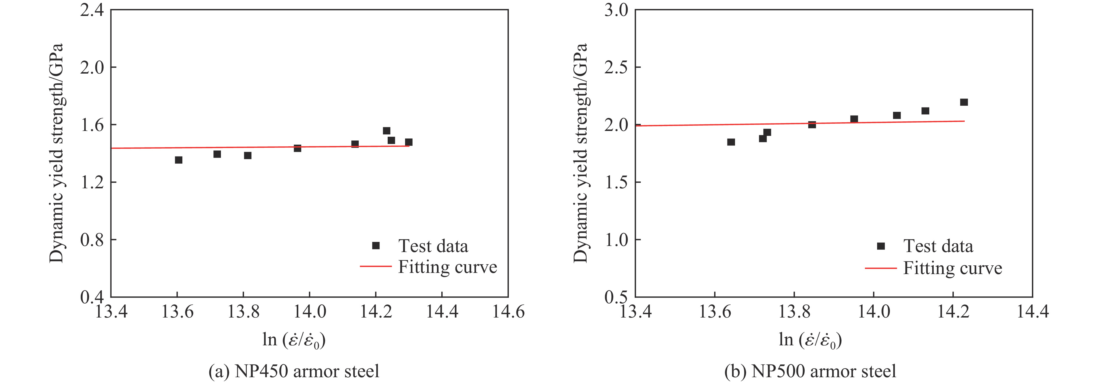
图 11 不同应变率下试件的真实应力-应变曲线
Figure 11. True stress-strain curves of specimens at different strain rates
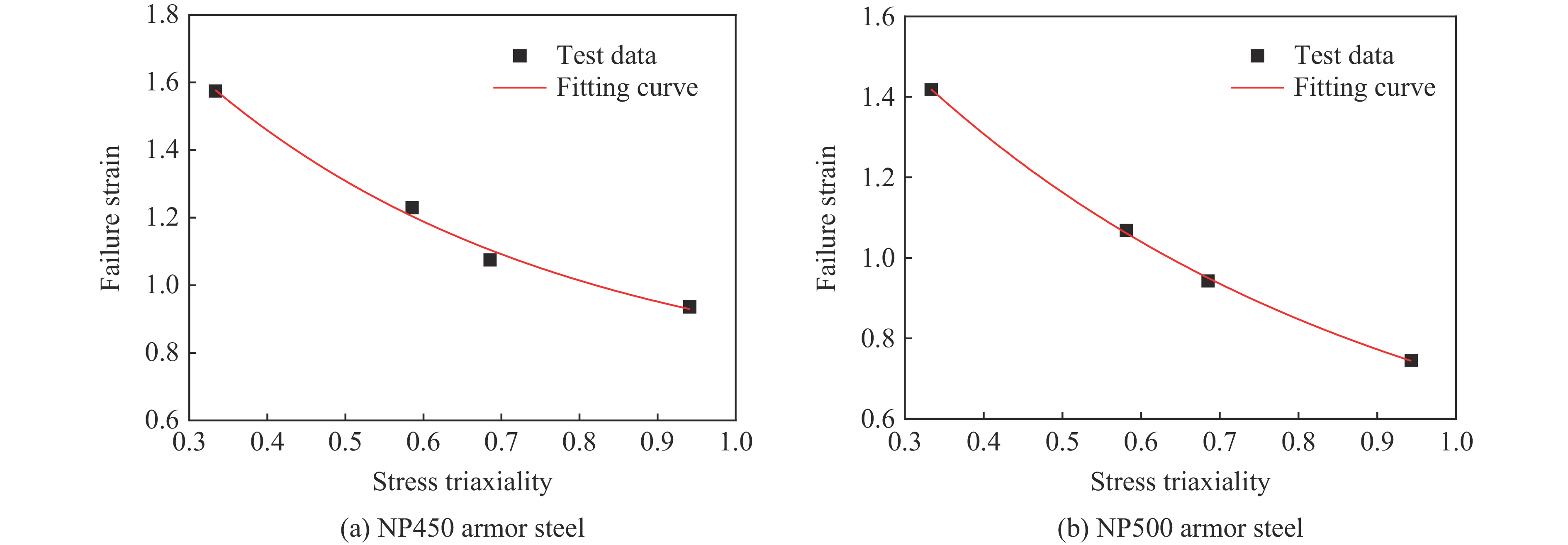
图 14 缺口试件拉伸试验数据与拟合曲线
Figure 14. Notched specimens tensile test data and fitting curves
图 21 NP450复合靶中弹体和靶体损伤
Figure 21. Damaged projectiles and targets in NP450/UHPC composite targets
图 22 NP500/UHPC复合靶中弹体和靶体损伤
Figure 22. Damaged projectiles and targets in NP500/UHPC composite targets
图 23 NP450_10mm复合靶中残余弹体长度与装甲钢损伤对比
Figure 23. Comparisons of residual projectile and damaged armor steel for NP450_10mm composite target

图 24 NP500_5 mm复合靶中残余弹体长度与UHPC中侵彻深度对比
Figure 24. Comparisons of residual projectile and penetration depth in UHPC for NP500_5 mm composite target
图 25 不同厚度装甲钢板的临界贯穿速度和弹头损伤云图
Figure 25. Critical perforation velocitiy and damage contours of projectile nose versus armor steel plate thickness
图 26 不同弹体冲击速度下复合靶体的破坏
Figure 26. Damage of composite targets subjected to different projectile striking velocities
图 27 不同冲击速度下6 mm厚NP450钢板和弹体的损伤过程
Figure 27. Failure process of the projectile and 6-mm-thickness NP450 armor steel plate at different striking velocities
图 28 不同冲击速度下6 mm厚NP500钢板和弹体的损伤过程
Figure 28. Failure process of the projectile and 6 mm thickness NP500 armor steel plate with different striking velocities
表 1 NP450和NP500装甲钢各组分的质量分数(%)
Table 1. The mass fraction (%) of each composition of NP450 and NP500 armor steels
钢材 C Si Mn P S Alt Ti Ni Cr Mo B Ceq NP450 0.20 0.51 1.29 0.01 0.008 0.041 0.02 0.02 0.66 0.15 0.0018 0.58 NP500 0.28 0.64 0.74 0.005 0.001 0.034 0.015 0.69 0.24 0.42 0.0016 0.60 注:Alt为全铝含量;Ceq代表carbon equivalent,即钢铁中各种合金元素折算成碳的含量。  下载: 导出CSV
表 2 UHPC配合比(kg/m3)
Table 2. Mixture proportions of UHPC (kg/m3)
水泥 硅灰 降粘性掺合料 河沙 水 高效减水剂 钢纤维掺量 700 140 110 1200 152 22.8 156
下载: 导出CSV
表 3 钢纤维材料性能
Table 3. Material properties of steel fiber
钢纤维 长度/mm 直径/mm 长径比 密度/(kg·m-3) 抗拉强度/MPa 弹性模量/GPa 微细平直型 13 0.2 65 7800 2800 210
下载: 导出CSV
表 4 试验数据
Table 4. Test data
试验编号 v0/(m·s−1) Lr/mm Mr/g h/mm ρA/(kg·m−2) d1/mm d2/mm d3/mm d4/mm dc/mm Hc/mm Ac/cm2 NP450_5 mm 474 168 673 126 345.4 250 275 260 250 259 85 493 NP450_5 mm 581 165 682 159 428.9 260 255 240 265 255 87 515 NP450_5 mm 639 169 680 175 469.4 210 250 245 230 234 125 419 NP450_8 mm 481 * * 32 123.5 115 125 125 120 121 24 478 NP450_10 mm 399 135 495 7 55.0 – – – – – – – NP450_13 mm 394 144 588 3 23.6 – – – – – – – NP500_5 mm 484 155 668 81 231.5 160 170 205 180 179 76 248 NP500_5 mm 584 160 676 130 355.5 220 290 280 270 265 82 478 NP500_5 mm 646 162 675 166 446.6 210 190 200 180 195 96 285 NP500_8 mm 643 * * 71 222.2 190 255 250 205 225 63 378 NP500_10 mm 422 129 476 4 31.4 – – – – – – – NP500_13 mm 372 134 520 1 7.9 – – – – – – – 注:“*”代表弹体在试验中破碎,未能得到弹体残余长度和质量,“–”表示钢板未被贯穿,可忽略UHPC靶的损伤。
下载: 导出CSV
表 5 缺口试件拉伸试验结果
Table 5. Tensile results of notched specimens
R/mm η0 Df/mm εf NP450 NP500 NP450 NP500 NP450计算 NP450平均 NP500计算 NP500平均 3 0.939 0.939 6.21 6.99 0.933 0.936 0.732 0.746 6.36 7.00 0.972 0.729 6.28 6.84 0.904 0.776 6 0.682 0.682 5.84 6.12 1.104 1.075 1.006 0.943 5.98 6.62 1.040 0.849 5.92 6.22 1.082 0.974 9 0.562 0.562 5.06 5.84 1.402 1.230 1.100 1.099 5.96 5.84 1.110 1.096 5.76 6.12 1.178 1.100 ∞ 0.333 0.333 4.58 4.89 1.562 1.575 1.433 1.418 4.56 4.99 1.569 1.392 4.52 4.89 1.590 1.430
下载: 导出CSV
表 6 弹体和装甲钢J-C本构模型强度参数
Table 6. J-C model strength parameters of projectile and armor steels
钢材 As/MPa Bs/MPa n Cs m ${\dot{\varepsilon } }_{0}$/s−1 30CrMnSiNi2A 1269 810 0.4790 0.04 1.0 1×10⁻³ NP450 1230 1647 0.4985 0.13 1.0 1×10⁻³ NP500 1370 2319 0.4435 0.0368 1.0 1×10⁻³
下载: 导出CSV
表 7 弹体和装甲钢J-C本构模型损伤参数
Table 7. J-C model damage parameters of projectile and armor steels
钢材 D1 D2 D3 D4 D5 30CrMnSiNi2A 0.239 8.593 −7.867 0.009 0 NP450 0.696 1.827 −2.184 0 0 NP500 0.358 1.844 −1.657 0 0
下载: 导出CSV
表 8 材料的状态方程参数
Table 8. Material's parameters of state equation
c0/(m·s−1) s1 s2 s3 γ0 a 4578 1.33 0 0 1.67 0.43
下载: 导出CSV
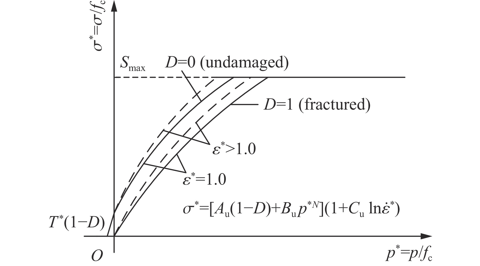
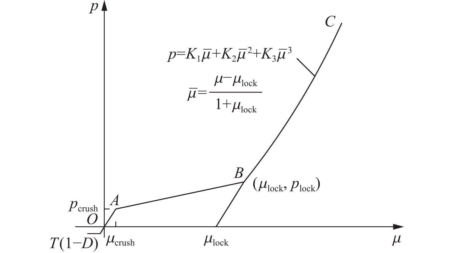
表 9 UHPC的HJC模型参数
Table 9. HJC model parameters of UHPC
ρ0/(kg·m−3) Au Bu N Cu Smax 2530 0.3 1.73 0.79 0.005 7 K1/GPa K2/GPa K3/GPa plock/GPa D1 D2 εf,min 116 -243 506 3.47 0.04 1 0.01
下载: 导出CSV
表 10 弹道特性结果
Table 10. Ballistic characterization results
试验编号 v0/(m·s−1) h0/mm h/mm Et Em q2 NP450_5mm 474 168.0 121 9.40 3.03 28.48 NP450_5mm 581 189.4 154 7.08 2.28 16.14 NP450_5mm 639 218.1 170 9.62 3.10 29.82 NP450_8mm 481 170.1 24 18.26 5.88 107.37 NP450_10mm 399 146.7 5 14.17 4.56 64.62 NP450_13mm 394 144.6 2 10.97 3.53 38.72 NP500_5mm 484 170.7 76 18.94 6.10 115.53 NP500_5mm 584 192.5 125 13.50 4.35 58.73 NP500_5mm 646 221.7 161 12.14 3.91 47.47 NP500_8mm 643 221.1 63 19.76 6.36 125.67 NP500_10mm 422 158.4 3 15.54 5.00 77.70 NP500_13mm 372 139.5 1.5 10.62 3.42 36.32
下载: 导出CSV
-
[1] SILSBY G F. Penetration of semi-infinite steel targets by tungsten rods at 1.3 to 4.5 km/s [C]// Proceeding of the 8th International Symposium on Ballistics. Orlando, USA: International Ballistics Society, 1984. [2] FRAS T, ROTH C C, MOHR D. Fracture of high-strength armor steel under impact loading [J]. International Journal of Impact Engineering, 2018, 111: 147–164. DOI: 10.1016/j.ijimpeng.2017.09.009. [3] FRAS T, ROTH C C, MOHR D. Dynamic perforation of ultra-hard high-strength armor steel: impact experiments and modeling [J]. International Journal of Impact Engineering, 2019, 131: 256–271. DOI: 10.1016/j.ijimpeng.2019.05.008. [4] CHOUDHARY S, SINGH P K, KHARE S, et al. Ballistic impact behaviour of newly developed armour grade steel: an experimental and numerical study [J]. International Journal of Impact Engineering, 2020, 140: 103557. DOI: 10.1016/j.ijimpeng.2020.103557. [5] FORRESTAL M J, ALTMAN B S, CARGILE J D, et al. An empirical equation for penetration depth of ogive-nose projectiles into concrete targets [J]. International Journal of Impact Engineering, 1994, 15(4): 395–405. DOI: 10.1016/0734-743X(94)80024-4. [6] FORRESTAL M J, FREW D J, HANCHAK S J, et al. Penetration of grout and concrete targets with ogive-nose steel projectiles [J]. International Journal of Impact Engineering, 1996, 18(5): 465–476. DOI: 10.1016/0734-743X(95)00048-F. [7] FORRESTAL M J, FREW D J, HICKERSON J P, et al. Penetration of concrete targets with deceleration-time measurements [J]. International Journal of Impact Engineering, 2003, 28(5): 479–497. DOI: 10.1016/S0734-743X(02)00108-2. [8] HANCHAK S J, FORRESTAL M J, YOUNG E R, et al. Perforation of concrete slabs with 48 MPa (7 ksi) and 140 MPa (20 ksi) unconfined compressive strengths [J]. International Journal of Impact Engineering, 1992, 12(1): 1–7. DOI: 10.1016/0734-743X(92)90282-X. [9] SOVJÁK R, VAVŘINÍK T, MÁCA P, et al. Experimental investigation of ultra-high performance fiber reinforced concrete slabs subjected to deformable projectile impact [J]. Procedia Engineering, 2013, 65: 120–125. DOI: 10.1016/j.proeng.2013.09.021. [10] SOVJÁK R, VAVŘINÍ T, ZATLOUKAL J, et al. Resistance of slim UHPFRC targets to projectile impact using in-service bullets [J]. International Journal of Impact Engineering, 2015, 76: 166–177. DOI: 10.1016/j.ijimpeng.2014.10.002. [11] MÁCA P, SOVJÁK R, KONVALINKA P. Mix design of UHPFRC and its response to projectile impact [J]. International Journal of Impact Engineering, 2014, 63: 158–163. DOI: 10.1016/j.ijimpeng.2013.08.003. [12] WU H, FANG Q, CHEN X W, et al. Projectile penetration of ultra-high performance cement based composites at 510–1320 m/s [J]. Construction and Building Materials, 2015, 74: 188–200. DOI: 10.1016/j.conbuildmat.2014.10.041. [13] WU H, FANG Q, GONG J, et al. Projectile impact resistance of corundum aggregated UHP-SFRC [J]. International Journal of Impact Engineering, 2015, 84: 38–53. DOI: 10.1016/j.ijimpeng.2015.05.007. [14] LIU J, WU C Q, LI J, et al. Ceramic balls protected ultra-high performance concrete structure against projectile impact: a numerical study [J]. International Journal of Impact Engineering, 2019, 125: 143–162. DOI: 10.1016/j.ijimpeng.2018.11.006. [15] SHAO R Z, WU C Q, SU Y, et al. Experimental and numerical investigations of penetration resistance of ultra-high strength concrete protected with ceramic balls subjected to projectile impact [J]. Ceramics International, 2019, 45(6): 7961–7975. DOI: 10.1016/j.ceramint.2019.01.110. [16] FENG J, SUN W W, LIU Z L, et al. An armour-piercing projectile penetration in a double-layered target of ultra-high-performance fiber reinforced concrete and armour steel: Experimental and numerical analyses [J]. Materials & Design, 2016, 102: 131–141. DOI: 10.1016/j.matdes.2016.04.021. [17] 李磊, 张先锋, 吴雪, 等. 不同硬度30CrMnSiNi2A钢的动态本构与损伤参数 [J]. 高压物理学报, 2017, 31(3): 239–248. DOI: 10.11858/gywlxb.2017.03.005.LI L, ZHANG X F, WU X, et al. Dynamic constitutive and damage parameters of 30CrMnSiNi2A steel with different hardness [J]. Chinese Journal of High Pressure Physics, 2017, 31(3): 239–248. DOI: 10.11858/gywlxb.2017.03.005. [18] 中华人民共和国建设部, 国家质量监督检验检疫总局. 普通混凝土力学性能试验方法标准: GB/T 50081—2002 [S]. 北京: 中国建筑工业出版社, 2003.Ministry of Construction, People’s Republic of China, General Administration of Quality Supervision, Inspection and Quarantine of the People’s Republic of China. Standard for test method of mechanical properties on ordinary concrete: GB/T 50081—2002 [S]. Beijing: China Architecture & Building Press, 2003. [19] ZHAI Y X, WU H, FANG Q. Impact resistance of armor steel/ceramic/UHPC layered composite targets against 30CrMnSiNi2A steel projectiles [J]. International Journal of Impact Engineering, 2021, 154: 103888. DOI: 10.1016/j.ijimpeng.2021.103888. [20] Livermore Software Technology Corporation. LS-DYNA keywords user’s manual [M]. Livermore: Livermore Software Technology Corporation, 2001. [21] JOHNSON G R, COOK W H. A constitutive model and data for metals subjected to large strains, high strain rates and high temperatures [C]// Proceedings of the 7th International Symposium on Ballistics. The Hague, 1983: 541-547. [22] JOHNSON G R, COOK W H. Fracture characteristics of three metals subjected to various strains, strain rates, temperatures and pressures [J]. Engineering Fracture Mechanics, 1985, 21(1): 31–48. DOI: 10.1016/0013-7944(85)90052-9. [23] 中华人民共和国国家质量监督检验检疫总局, 中国国家标准化管理委员会. 金属材料 拉伸试验 第1部分: 室温试验方法: GB/T 228.1—2010 [S]. 北京: 中国标准出版社, 2010.General Administration of Quality Supervision, Inspection and Quarantine of the People’s Republic of China, Standardization Administration of the People’s Republic of China. Metallic materials-tensile testing-Part 1: method of test at room temperature: GB/T 228.1—2010 [S]. Beijing: Standards Press of China, 2010. [24] DEY S, BØRVIK T, HOPPERSTAD O S, et al. The effect of target strength on the perforation of steel plates using three different projectile nose shapes [J]. International Journal of Impact Engineering, 2004, 30(8/9): 1005–1038. DOI: 10.1016/j.ijimpeng.2004.06.004. [25] BØRVIK T, DEY S, CLAUSEN A H. Perforation resistance of five different high-strength steel plates subjected to small-arms projectiles [J]. International Journal of Impact Engineering, 2009, 36(7): 948–964. DOI: 10.1016/j.ijimpeng.2008.12.003. [26] BØRVIK T. DEY S, CLAUSEN A H. A preliminary study on the perforation resistance of high-strength steel plates [J]. Journal de Physique IV, 2006, 134: 1053–1059. DOI: 10.1051/jp4:2006134161. [27] STEINBERG D J. Equation of state and strength properties of selected materials: UCRL-MA-106439 [R]. Livermore: Lawrence Livermore National Laboratory, 1996. [28] HOLMQUIST T J, JOHNSON G R. A computational constitutive model for glass subjected to large strains, high strain rates and high pressures [J]. Journal of Applied Mechanics, 2011, 78(5): 051003. DOI: 10.1115/1.4004326. [29] REN G M, WU H, FANG Q, et al. Parameters of Holmquist-Johnson-Cook model for high-strength concrete-like materials under projectile impact [J]. International Journal of Protective Structures, 2017, 8(3): 352–367. DOI: 10.1177/2041419617721552. [30] WU H, LI Y C, FANG Q, et al. Scaling effect of rigid projectile penetration into concrete target: 3D mesoscopic analyses [J]. Construction and Building Materials, 2019, 208: 506–524. DOI: 10.1016/j.conbuildmat.2019.03.040. [31] LIU F, FENG W H, XIONG Z, et al. Impact performance of new prestressed high-performance concrete pipe piles manufactured with an environmentally friendly technique [J]. Journal of Cleaner Production, 2019, 231: 683–697. DOI: 10.1016/j.jclepro.2019.05.241. [32] CAO Y Y Y, YU Q L, TANG W H, et al. Numerical investigation on ballistic performance of coarse-aggregated layered UHPFRC [J]. Construction and Building Materials, 2020, 250: 118867. DOI: 10.1016/j.conbuildmat.2020.118867. [33] GOOCH W A, BURKINS M S, PALICKA J J. Ballistic development of U.S. high density tungsten carbide ceramics [C]// International Conference on Advanced Ceramics and Glasses. Hawaii, 2001: 53–61. [34] MADHU V, RAMANJANEYULU K, BHAT T B, et al. An experimental study of penetration resistance of ceramic armour subjected to projectile impact [J]. International Journal of Impact Engineering, 2005, 32(1/2/3/4): 337–350. DOI: 10.1016/j.ijimpeng.2005.03.004. [35] BØRVIK T, HOPPERSTAD O S, BERSTAD T, et al. Perforation of 12 mm thick steel plates by 20 mm diameter projectiles with flat, hemispherical and conical noses: Part II: numerical simulations [J]. International Journal of Impact Engineering, 2002, 27(1): 37–64. DOI: 10.1016/S0734-743X(01)00035-5. [36] WANG Y P, CHEN X Z, XIAO X K, et al. Effect of Lode angle incorporation into a fracture criterion in predicting the ballistic resistance of 2024-T351 aluminum alloy plates struck by cylindrical projectiles with different nose shapes [J]. International Journal of Impact Engineering, 2020, 139: 103498. DOI: 10.1016/j.ijimpeng.2019.103498. -


计量
- 文章访问数: 689
- HTML全文浏览量: 746
- PDF下载量: 174
- 被引次数: 0