


Experimental and numerical simulation research on damage effect of jetting projectile charge (JPC) on reinforced concrete wall
-
摘要: 为了满足高侵深和大穿孔的要求,设计一种聚能杆式弹丸(jetting projectile charge, JPC),开展大尺寸钢筋混凝土墙的毁伤效应试验。在此基础上,基于修正参数的K&C(Karagozian & Case)模型进行数值模拟,研究JPC高速侵彻和爆炸冲击波对钢筋混凝土墙的联合破坏作用,分析墙体厚度对破坏效果的影响规律。结果表明,在1.67倍和2.50倍装药直径的炸高条件下,JPC均能够有效贯穿80 cm(6.67倍装药直径)厚的钢筋混凝土墙,形成直径大于6 cm(0.50倍装药直径)的柱状孔洞;聚能装药的多载荷毁伤特性决定了钢筋混凝土墙的破坏结果,爆炸冲击波能够加剧墙体正面开坑和背面崩落的破坏范围;墙体厚度对于墙体正面漏斗坑的直径与深度及内部侵彻孔洞直径均无显著影响;随着墙体厚度增大,背面漏斗坑直径逐渐减小,深度却逐渐增大。
-
关键词:
- 聚能杆式弹丸(JPC) /
- 钢筋混凝土墙 /
- 侵彻 /
- 冲击波 /
- 联合破坏
Abstract: To meet the requirements of a tandem penetrating warhead for high penetration depth and large perforation, a jetting projectile charge (JPC) was designed. The damage test of a large-scale reinforced concrete wall was carried out to analyze the impact of standoff distance on the damaging effect. By constructing a large air domain covering the whole reinforced concrete wall for the transmission of explosion shock wave and JPC, the coupling damage of JPC high-speed penetration and explosion shock wave to the reinforced concrete wall was considered. The damage evolution, strain rate and other parameters of the Karagozian & Case (K&C) model were modified, based on which a numerical model was established to simulate the whole process of the combined damage of JPC and explosion shock wave to the reinforced concrete wall. The reliability of the numerical model was fully verified by comparing the simulation and test results from the failure mode, crater depth and crater diameter of the reinforced concrete wall. On this basis, the combined damage effect of JPC and explosion shock wave on the reinforced concrete wall was further studied, and the influence of wall thickness on the damaging effect was analyzed. The results show that JPC can penetrate the reinforced concrete wall with a thickness of 80 cm (6.67 times of charge diameter) at the standoff distance of 1.67 times and 2.50 times of charge diameter, and form cylindrical holes with a diameter of more than 6 cm (0.50 times of charge diameter). The multi-load damage characteristic of shaped charge determines the damage result of the reinforced concrete wall, and the explosion shock wave can intensify the damage range of the front crater and back crater of the reinforced concrete wall. The wall thickness has no significant effect on the diameter and depth of the crater on the front of the wall and the diameter of the internal penetration hole. With the increase of the wall thickness, the crater diameter on the back gradually decreases and the crater depth on the back gradually increases.-
Key words:
- jetting projectile charge (JPC) /
- reinforced concrete wall /
- penetration /
- shock wave /
- combined damage
-

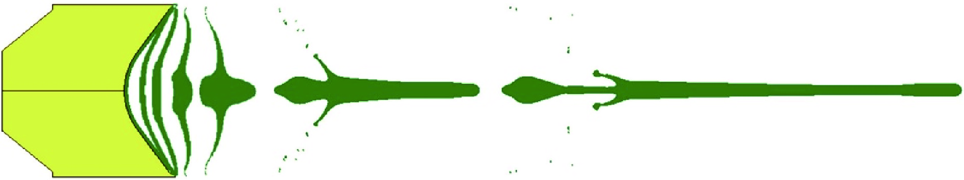
图 2 JPC成型过程(t=0, 15, 18, 24, 31, 62, 131 μs)
Figure 2. Forming process of the JPC (t=0, 15, 18, 24, 31, 62, 131 μs)
图 4 JPC成型参数随炸高变化
Figure 4. Forming parameters of the JPC varing with standoff distance

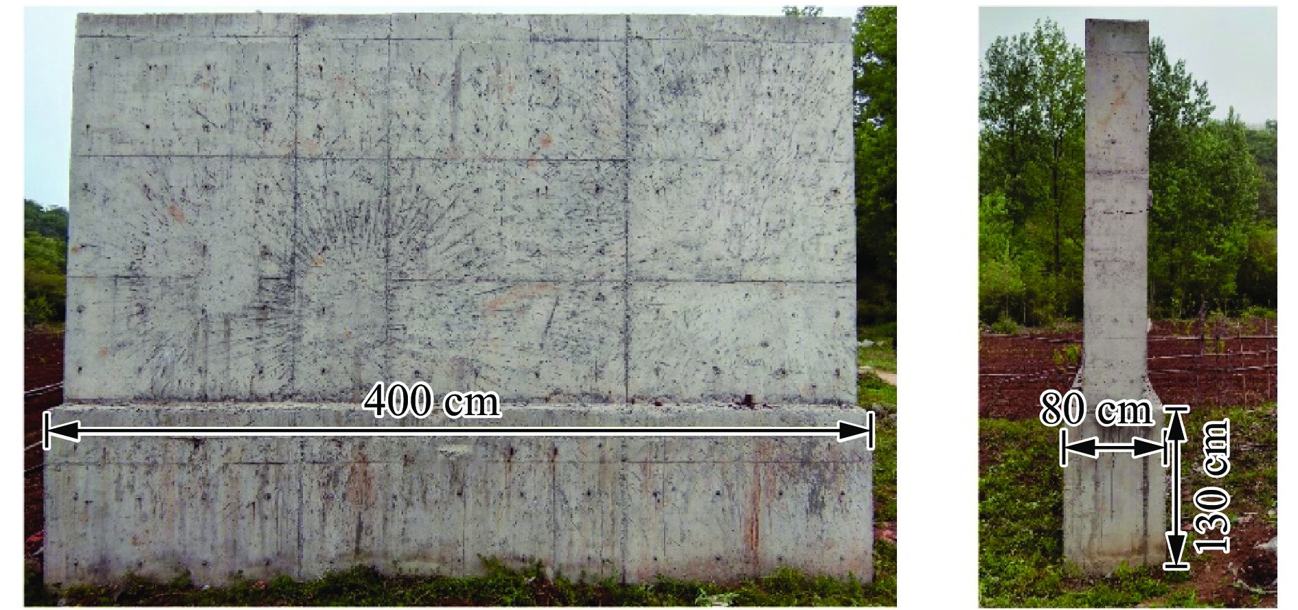
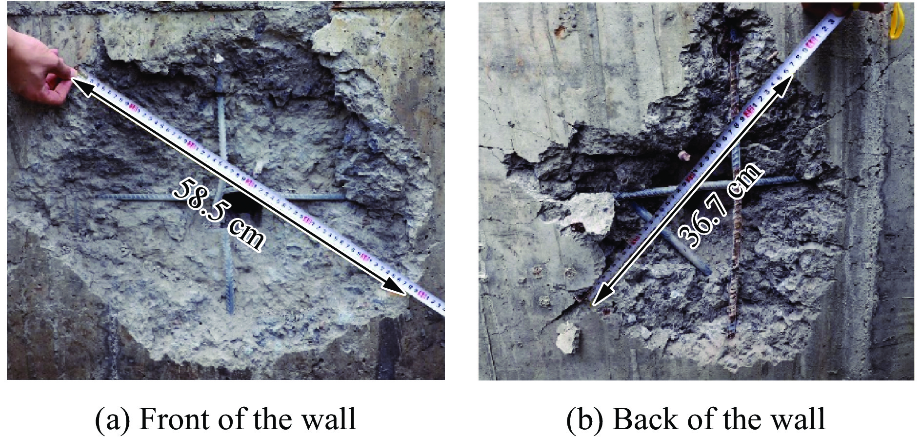
图 7 钢筋混凝土墙的破坏结果(炸高20 cm)
Figure 7. Failure of the reinforced concrete wall (standoff distance is 20 cm)
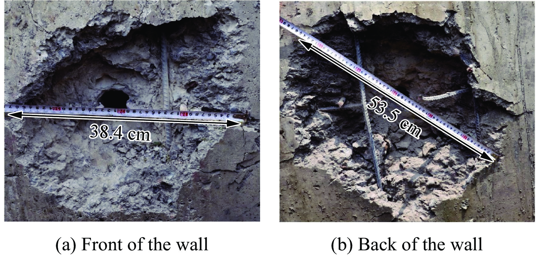
图 8 钢筋混凝土墙的破坏结果(炸高30 cm)
Figure 8. Failure of the reinforced concrete wall (standoff distance is 30 cm)
图 10 JPC聚能装药破坏钢筋混凝土墙的数值模型
Figure 10. Numerical model of reinforced concrete wall damaged by the JPC

图 11 钢筋混凝土墙破坏的数值模拟结果
Figure 11. Numerical simulation results of reinforced concrete wall failure
图 12 JPC聚能装药破坏钢筋混凝土墙的应力云图
Figure 12. Stress cloud diagram of reinforced concrete wall damaged by the JPC

图 13 钢筋混凝土墙背面破坏过程
Figure 13. Failure process of the back of the reinforced concrete wall
图 14 钢筋混凝土墙破坏的应力云图
Figure 14. Stress cloud diagram of failure of reinforced concrete wall
图 15 减小空气域后JPC聚能装药破坏钢筋混凝土墙的数值模型
Figure 15. Numerical model of reinforced concrete wall damaged by the JPC after reducing air domain

图 16 不同尺寸空气域的数值模拟结果对比(炸高20 cm)
Figure 16. Comparison of numerical simulation results of different air domains (standoff distance is 20 cm)
图 17 不同尺寸空气域的数值模拟结果对比(炸高30 cm)
Figure 17. Comparison of numerical simulation results of different air domains (standoff distance is 30 cm)
图 18 不同厚度钢筋混凝土墙的损伤分布
Figure 18. Damage distribution of the reinforced concrete wall with different thicknesses

图 19 不同厚度钢筋混凝土墙的破坏变化
Figure 19. Damage of reinforced concrete wall with different thicknesses
ρ/(g·cm−3) C4 C5 E0/MPa V 1.225×10⁻³ 0.4 0.4 0.25 1  下载: 导出CSV
ρ/(g·cm−3) A/GPa B/GPa R1 R2 ω E0/GPa 1.7 630 6.801 4.1 1.3 0.36 10
下载: 导出CSV
ρ/(g·cm−3) A/GPa B/GPa n c m Tm/K Tr/K 8.96 0.09 0.292 0.31 0.025 1.09 1356 293
下载: 导出CSV
表 4 钢筋混凝土墙毁伤试验结果
Table 4. Test results of the reinforced concrete wall
炸高/cm D1/cm D2/cm D3/cm D4/cm H1/cm H2/cm 20 57.5 40.5 6.5 6.2 9.8 10.4 30 39.3 54.8 6.3 6.5 8.8 12.6
下载: 导出CSV
表 5 混凝土材料参数
Table 5. Material parameters of concrete
ρ/(g·cm−3) A0/MPa 泊松比 b1 b2 长度单位换算系数 压力单位换算系数 2.3 28 0.2 0.82 1.03 0.3937 1.45×10⁷
下载: 导出CSV
表 6 钢筋混凝土墙破坏的数值模拟与试验结果对比(炸高20 cm)
Table 6. Comparison between numerical simulation results and test results (standoff distance is 20 cm)
方法 D1/cm D2/cm D3/cm D4/cm H1/cm H2/cm 试验结果 57.5 40.5 6.5 6.2 9.8 10.4 数值模拟 62.4 44.4 5.9 5.6 9.4 11.5 相对误差/% 8.5 9.6 9.2 9.7 4.1 10.6
下载: 导出CSV
表 7 钢筋混凝土墙破坏的数值模拟与试验结果对比(炸高30 cm)
Table 7. Comparison between numerical simulation results and test results (standoff distance is 30 cm)
方法 D1/cm D2/cm D3/cm D4/cm H1/cm H2/cm 试验结果 39.3 54.8 6.3 6.5 8.8 12.6 数值模拟 42.2 55.6 5.8 6.8 8.9 13.1 相对误差/% 7.4 1.5 7.9 4.6 1.1 4.0
下载: 导出CSV
表 8 不同厚度钢筋混凝土墙破坏的数值模拟结果
Table 8. Simulation results of reinforced concrete wall with different thickness
δ/cm D1/cm D2/cm D3/cm D4/cm H1/cm H2/cm H3/cm H3/δ 60 63.2 64.2 5.9 4.6 9.2 8.6 42.2 0.703 70 61.8 52.6 5.9 5.5 9.2 10.6 50.2 0.717 80 62.4 44.4 5.9 5.6 9.4 11.5 59.1 0.738 90 63.4 38.8 5.8 5.7 9.6 13.8 66.6 0.740 100 62.8 27.6 5.8 5.6 9.5 16.2 74.3 0.743
下载: 导出CSV
-
[1] 张雷雷, 黄风雷, 段卓平. 爆炸成型杆式侵彻体对混凝土靶侵彻研究 [J]. 弹箭与制导学报, 2006(SA): 1140–1142. DOI: 10.3969/j.issn.1673-9728.2006.02.361.ZHANG L L, HUANG F L, DUAN Z P. Studies about jetting projectiles charge’s penetration to concrete target [J]. Journal of Projectiles, Rockets, Missiles and Guidance, 2006(SA): 1140–1142. DOI: 10.3969/j.issn.1673-9728.2006.02.361. [2] 李成兵, 沈兆武, 裴明敬. 聚能杆式弹丸侵彻混凝土实验研究 [J]. 振动与冲击, 2007(7): 85–88,183. DOI: 10.3969/j.issn.1000-3835.2007.07.020.LI C B, SHEN Z W, PEI M J. Experimental investigation of rod-shaped projectile penetrating concrete [J]. Journal of Vibration and Shock, 2007(7): 85–88,183. DOI: 10.3969/j.issn.1000-3835.2007.07.020. [3] 顾文彬, 胡亚峰, 刘建青, 等. 基于等质量变壁厚球缺罩聚能杆式射流成型特性研究 [J]. 爆破器材, 2013, 42(4): 14–19. DOI: 10.3969/j.issn.1001-8352.2013.04.004.GU W B, HU Y F, LIU J Q, et al. Characteristic study on jetting projectile charge formation of variable thickness sphere liner based on equi-mass [J]. Explosive Materials, 2013, 42(4): 14–19. DOI: 10.3969/j.issn.1001-8352.2013.04.004. [4] 付恒, 陈智刚. 等壁厚球缺形装药结构优化设计 [J]. 爆破器材, 2016, 45(5): 17–22. DOI: 10.3969/j.issn.1001-8352.2016.05.004.FU H, CHEN Z G. Optimization design of hemispherical charge structure with equal thickness [J]. Explosive Materials, 2016, 45(5): 17–22. DOI: 10.3969/j.issn.1001-8352.2016.05.004. [5] 张钧, 陈智刚, 李小军, 等. 变壁厚球缺罩杆式射流的形成与侵彻性能研究 [J]. 爆破器材, 2016, 45(1): 39–42. DOI: 10.3969/j.issn.1001-8352.2016.01.009.ZHANG J, CHEN Z G, LI X J, et al. Formation and penetration performances of jetting penetrator charge of hemispherical liners with variable thickness [J]. Explosive Materials, 2016, 45(1): 39–42. DOI: 10.3969/j.issn.1001-8352.2016.01.009. [6] 王维占, 冯顺山, 李小军, 等. 局部变壁厚球缺型药型罩侵彻威力性能的数值模拟及试验验证 [J]. 火炸药学报, 2018, 41(4): 420–424. DOI: 10.14077/j.issn.1007-7812.2018.04.018.WANG W Z, FENG S S, LI X J, et al. Numerical simulation and experimental verification of the penetrating power performance of hemispherical liner with locally variable-walled thickness [J]. Chinese Journal of Explosives & Propellants, 2018, 41(4): 420–424. DOI: 10.14077/j.issn.1007-7812.2018.04.018. [7] 张毅, 王志军, 崔斌, 等. 不同结构钛合金罩战斗部侵彻混凝土数值模拟 [J]. 兵器材料科学与工程, 2015, 38(2): 95–98. DOI: 10.14024/j.cnki.1004-244x.2015.02.008.ZHANG Y, WANG Z J, CUI B, et al. Numerical simulation on concrete target penetrated by warhead of different titanium alloy shaped charge [J]. Ordnance Material Science and Engineering, 2015, 38(2): 95–98. DOI: 10.14024/j.cnki.1004-244x.2015.02.008. [8] LI J, HAO H. Numerical study of concrete spall damage to blast loads [J]. International Journal of Impact Engineering, 2014, 68: 41–55. DOI: 10.1016/j.ijimpeng.2014.02.001. [9] WU J, ZHOU Y M, ZHANG R, et al. Numerical simulation of reinforced concrete slab subjected to blast loading and the structural damage assessment [J]. Engineering Failure Analysis, 2020, 118: 104926. DOI: 10.1016/j.engfailanal.2020.104926. [10] HU F, WU H, FANG Q, et al. Numerical simulations of shaped charge jet penetration into concrete-like targets [J]. International Journal of Protective Structures, 2017, 8(2): 237–259. DOI: 10.1177/2041419617706863. [11] LI W B, WANG X M, LI W B. The effect of annular multi-point initiation on the formation and penetration of an explosively formed penetrator [J]. International Journal of Impact Engineering, 2010, 37(4): 414–424. DOI: 10.1016/j.ijimpeng.2009.08.008. [12] GERAMI N D, LIAGHAT G H, MOGHADAS G H R S, et al. Analysis of liner effect on shaped charge penetration into thick concrete targets [J]. Journal of the Brazilian Society of Mechanical Sciences and Engineering, 2017, 39(8): 3189–3201. DOI: 10.1007/s40430-017-0797-6. [13] WANG C, MA T B, NING J G. Experimental investigation of penetration performance of shaped charge into concrete targets [J]. Acta Mechanica Sinica, 2008, 24(3): 345. DOI: 10.1007/s10409-008-0160-3. [14] WU Y C, CRAWFORD J E. Numerical modeling of concrete using a partially associative plasticity model [J]. Journal of Engineering Mechanics, 2015, 141(12): 04015051. DOI: 10.1061/(ASCE)EM.1943-7889.0000952. [15] HONG J, FANG Q, CHEN L, et al. Numerical predictions of concrete slabs under contact explosion by modified K&C material model [J]. Construction and Building Materials, 2017, 155(11): 1013–1024. DOI: 10.1016/j.conbuildmat.2017.08.060. [16] MAO L, BARNETT S, BEGG D, et al. Numerical simulation of ultra high performance fibre reinforced concrete panel subjected to blast loading [J]. International Journal of Impact Engineering, 2014, 64: 91–100. DOI: 10.1016/j.ijimpeng.2013.10.003. [17] KONG X Z, FANG Q, LI Q M, et al. Modified K&C model for cratering and scabbing of concrete slabs under projectile impact [J]. International Journal of Impact Engineering, 2017, 108: 217–228. DOI: 10.1016/j.ijimpeng.2017.02.016. [18] LIN X S, GRAVINA R J. An effective numerical model for reinforced concrete beams strengthened with high performance fibre reinforced cementitious composites [J]. Materials and Structures, 2017, 50(5): 212. DOI: 10.1617/s11527-017-1085-8. [19] LEE M J, PARK G K, KIM S W, et al. Damage characteristics of high-performance fiber-reinforced cement composites panels subjected to projectile impact [J]. International Journal of Mechanical Sciences, 2022, 214: 106919. DOI: 10.1016/j.ijmecsci.2021.106919. [20] CRAWFORD J E, WU Y C, MAGALLANES J M, et al. The importance of shear-dilatancy behaviors in RC columns [J]. International Journal of Protective Structures, 2013, 4(3): 341–377. DOI: 10.1260/2041-4196.4.3.341. [21] LI J, ZHANG Y X. Evaluation of constitutive models of hybrid-fibre engineered cementitious composites under dynamic loadings [J]. Construction and Building Materials, 2012, 30: 149–160. DOI: 10.1016/j.conbuildmat.2011.11.031. [22] 许香照, 马天宝, 郝莉. 大口径聚能装药侵彻厚混凝土靶板的数值模拟及实验研究 [J]. 中国科学:技术科学, 2016, 46(4): 339–348. DOI: 10.1360/N092016-00004.XU X Z, MA T B, HAO L. Experimental and numerical investigation on heavy-caliber shaped-charge penetration in thick concrete target [J]. Scientia Sinica: Technologica, 2016, 46(4): 339–348. DOI: 10.1360/N092016-00004. [23] ABDEL-KADER M. Numerical predictions of the behaviour of plain concrete targets subjected to impact [J]. International Journal of Protective Structures, 2018, 9(3): 313–346. DOI: 10.1177/2041419618759109. [24] XU H, WEN H M. Semi-empirical equations for the dynamic strength enhancement of concrete-like materials [J]. International Journal of Impact Engineering, 2013, 60: 76–81. DOI: 10.1016/j.ijimpeng.2013.04.005. [25] MALVAR L J, ROSS C. A review of strain rate effects for concrete in tension [J]. ACI Materials Journal, 1998, 95: 735–739. [26] KONG X Z, FANG Q, ZHANG J H, et al. Numerical prediction of dynamic tensile failure in concrete by a corrected strain-rate dependent nonlocal material model [J]. International Journal of Impact Engineering, 2020, 137: 103445. DOI: 10.1016/j.ijimpeng.2019.103445. [27] Comite Euro-International Du Beton. CEB-FIP model code 1990: design code[M]. London:Thomas Telford Publishing, 1993. [28] YANKELEVSKY D, FELDGUN V. The embedment of a high velocity rigid ogive nose projectile into a concrete target [J]. International Journal of Impact Engineering, 2020, 144: 103631. DOI: 10.1016/j.ijimpeng.2020.103631. [29] LI Q M, TONG D J. Perforation thickness and ballistic limit of concrete target subjected to rigid projectile impact [J]. Journal of Engineering Mechanics, 2003, 129(9): 1083–1091. DOI: 10.1061/(ASCE)0733-9399(2003)129:9(1083. [30] LI P P, BROUWERS H J H, YU Q L. Influence of key design parameters of ultra-high performance fibre reinforced concrete on in-service bullet resistance [J]. International Journal of Impact Engineering, 2020, 136: 103434. DOI: 10.1016/j.ijimpeng.2019.103434. [31] MENG C M, TAN Q H, JIANG Z G, et al. Approximate solutions of finite dynamic spherical cavity-expansion models for penetration into elastically confined concrete targets [J]. International Journal of Impact Engineering, 2018, 114: 182–193. DOI: 10.1016/j.ijimpeng.2018.01.001. [32] CAO Y Y, YU Q L, TANG W H, et al. Numerical investigation on ballistic performance of coarse-aggregated layered UHPFRC [J]. Construction and Building Materials, 2020, 250: 118867. DOI: 10.1016/j.conbuildmat.2020.118867. -


计量
- 文章访问数: 769
- HTML全文浏览量: 337
- PDF下载量: 113
- 被引次数: 0