


Shock tube tests and dynamic behavior analyses on one-way masonry-infilled walls
-
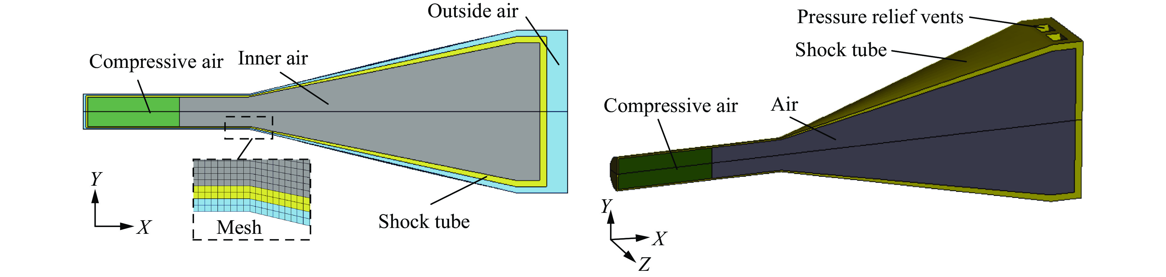
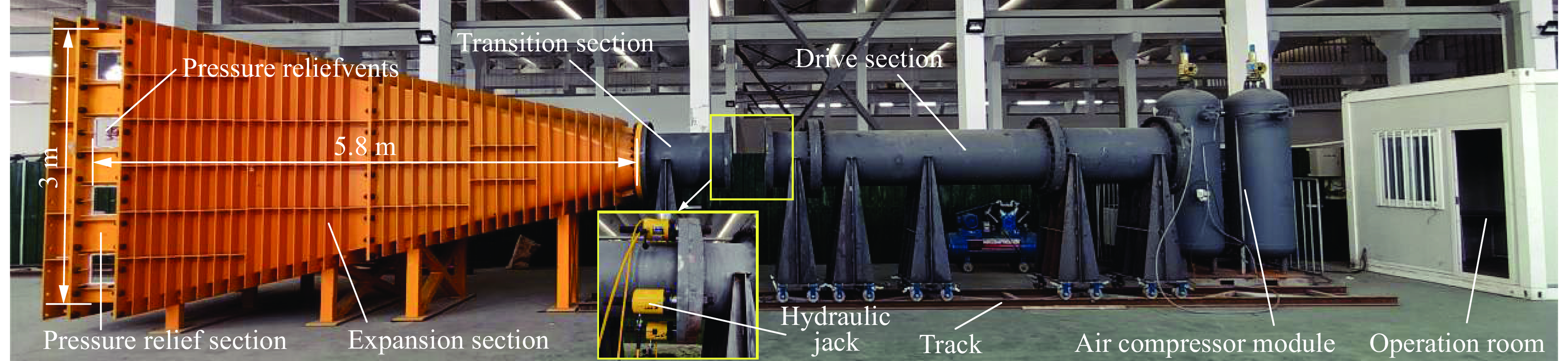
摘要: 为研究远场爆炸荷载作用下单向砌体填充墙的动力行为及其失效破坏机理,首先,基于研发的压缩空气驱动大截面(3 m×3 m)激波管开展了两面不同厚度单向实心砌体填充墙的面外加载试验,获得了作用在墙体表面的反射超压荷载时程、墙体面外挠度时程及墙体的变形失效模式。其次,建立了激波管精细化有限元模型,提出了砌体墙简化微观有限元建模方法,以及扩展砖块的Riedel-Hiermaier-Thoma材料模型和接缝的内聚力接触模型参数取值计算方法,对激波管中的压力传播以及试验墙体面外动态响应和损伤破坏开展了数值模拟。最后,基于爆炸荷载作用下单向砌体填充墙面外抗力方程和等效单自由度模型对试验墙体中心点面外挠度时程进行预测。结果表明:减小墙体高厚比可以增大框架拱推力,从而显著提升墙体的抗爆性能,厚105 mm的墙体在经历1次激波管试验后发生倒塌,而厚235 mm的墙体在经历6次激波管试验后仅有轻微损伤;墙体表面反射超压荷载时程的试验和数值模拟结果均为均布脉冲型荷载,且两者吻合很好,验证了激波管设计和激波管精细化有限元模型的合理性;数值模拟和理论预测的墙体动力行为与试验结果吻合较好,可为砌体填充墙抗爆评估与分析提供参考。Abstract: Masonry-infilled walls (MIWs) are prone to crack, fragment, and even collapse under blast loads, attributed to their low strength and weak ductility, which threatens the safety of building structures and the inside occupants and equipment. Aiming to study the dynamic behaviors and failure mechanism of one-way solid MIWs under far-field range explosion, the out-of-plane loading tests on two one-way solid MIWs with different thicknesses were first carried out based on the developed compressed air-driven large cross-section (3 m×3 m) shock tube. The reflected overpressures-time histories that acted on the MIWs, the deflection-time histories, and the deformation failure mode of MIWs were obtained. Then, a refined finite element model of the shock tube was established, and the simplified micro finite element modeling approach of MIWs, as well as the parameter calculation methods of the Riedel-Hiermaier-Thoma material model for expanded masonry blocks and the cohesive contact model for joints, were proposed. The pressure propagation in the shock tube and the out-of-plane dynamic responses and damage of MIWs were further numerically simulated. Finally, the central deflection-time histories of test walls were predicted based on the out-of-plane resistance function and equivalent single-degree-of-freedom model of one-way MIWs under blast loads. It indicated that reducing the height-to-thickness ratio of walls can increase the frame arch thrust, which could significantly improve the blast resistance performance of the MIWs. A105-mm-thick MIW collapsed after one shot, while a 235-mm-thick MIW was slightly damaged after six shots. Both the test and simulation results of reflected overpressure-time histories acted on the surface of MIWs were uniform pulse loads and in good agreement, which validated the reasonability of the design and refined finite element model of the shock tube. The predicted dynamic behaviors of MIWs by the numerical simulation and theoretical calculation method were in good accordance with test data, which can provide a reference for blast-resistant assessment and analysis of MIWs.
-
Key words:
- shock tube /
- blast load /
- masonry-infilled wall /
- dynamic behavior /
- out-of-plane loading /
- reflected overpressure
-
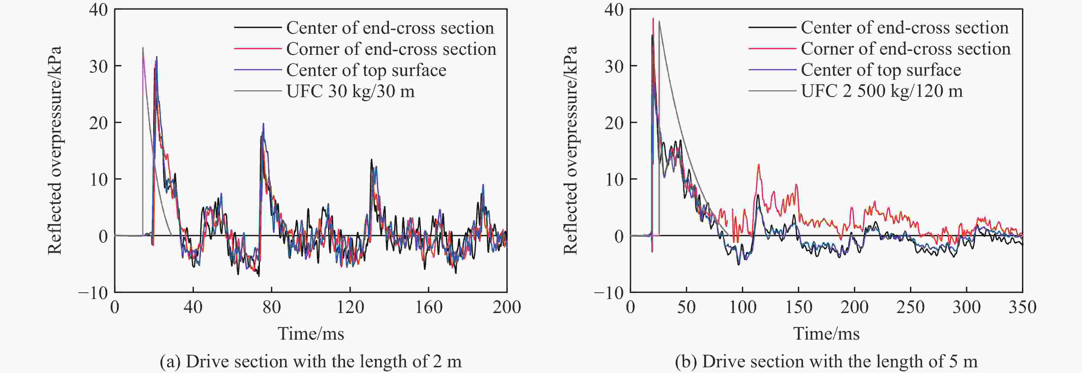
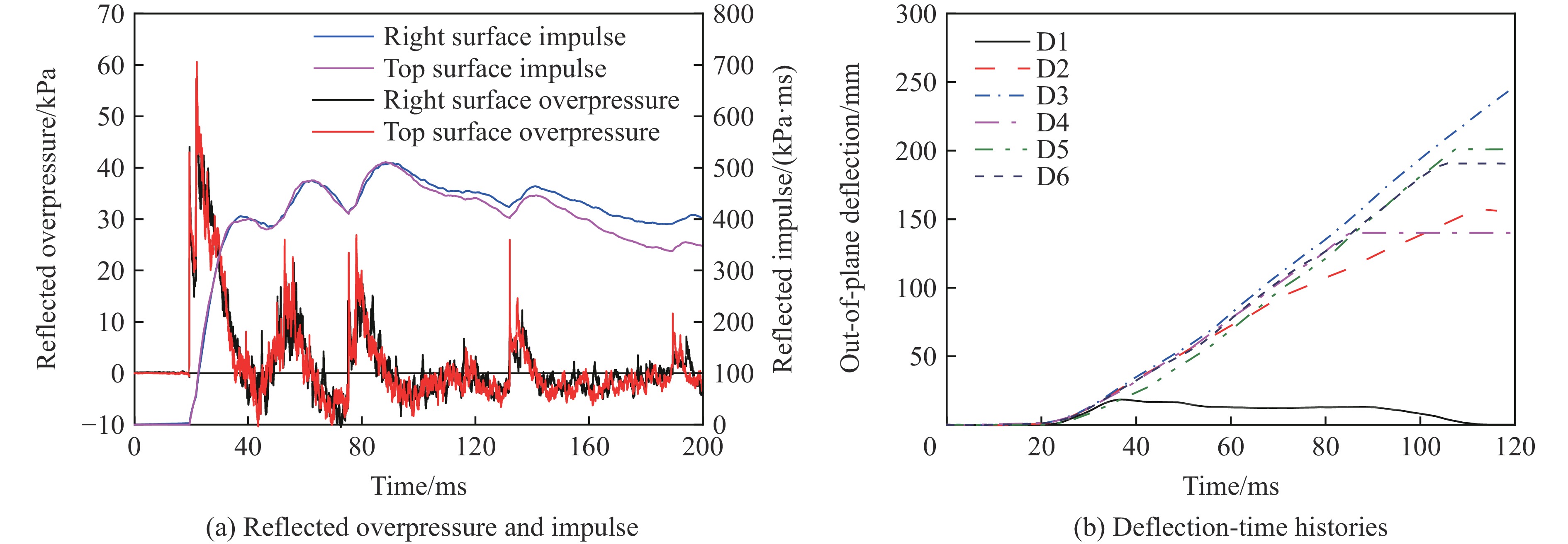
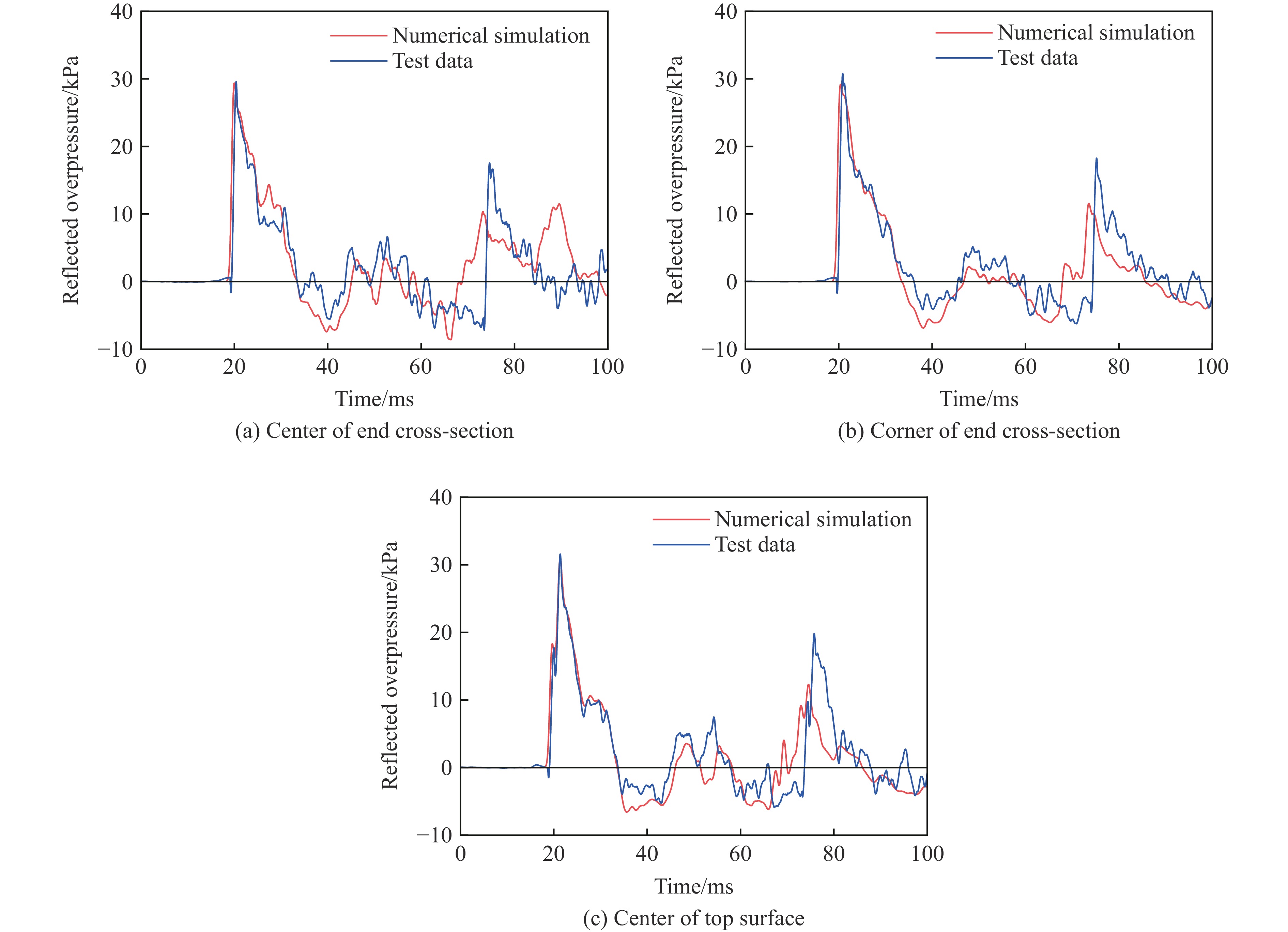
图 3 预试验中不同测点的反射超压时程
Figure 3. Reflected overpressure-time histories at different measuring points in pre-test
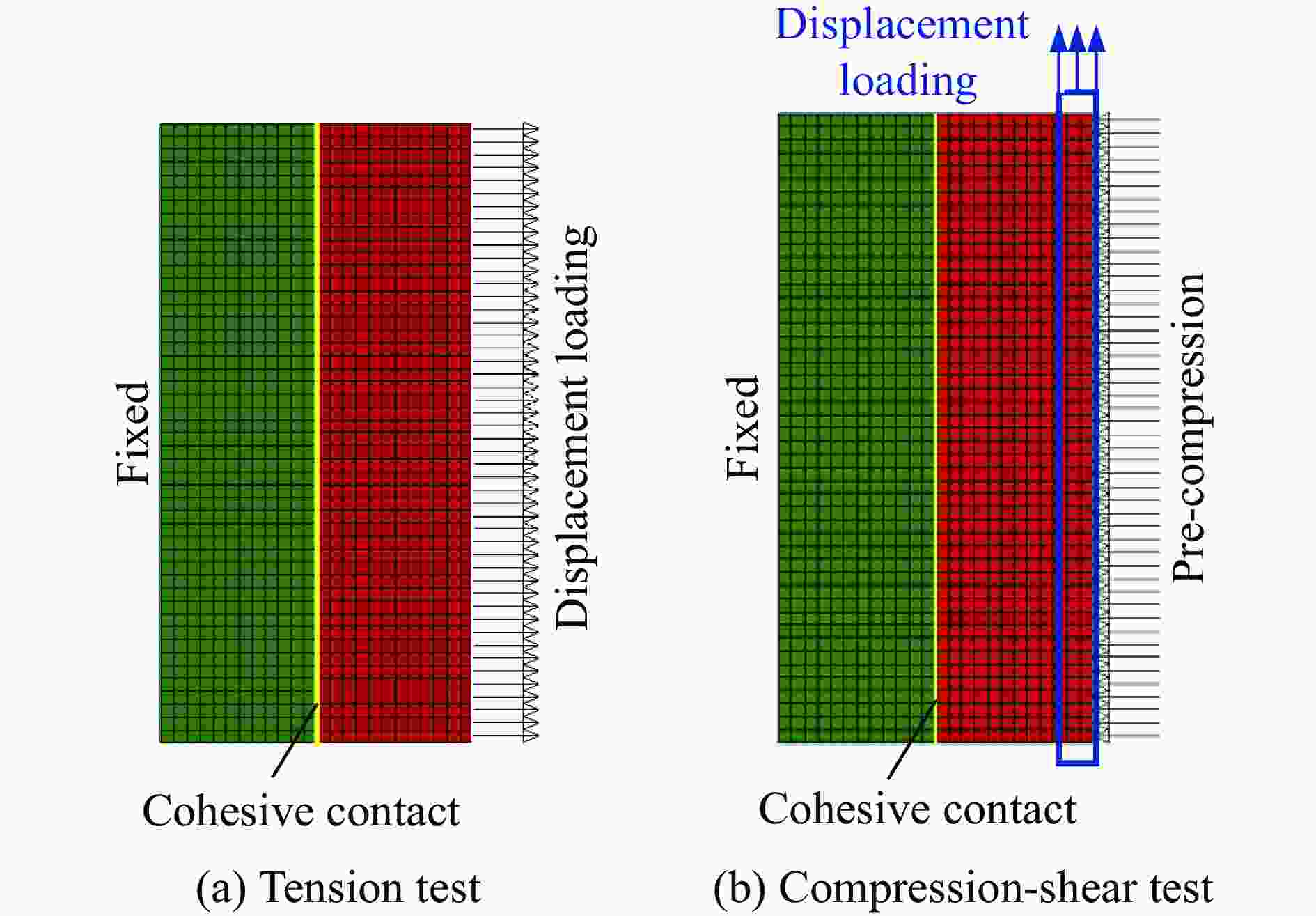
图 11 砖-砂浆-砖组合体试验示意图
Figure 11. Schematic diagrams of brick-mortar-brick assembly tests

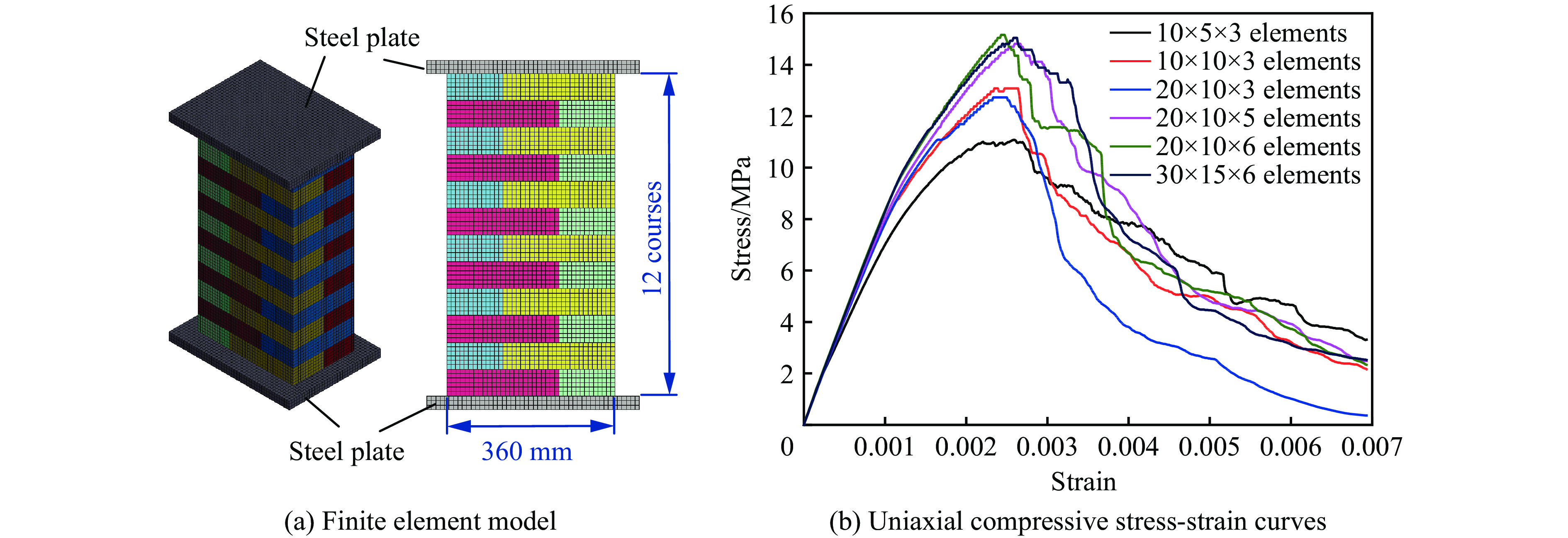
图 13 砌体棱柱体模型和网格敏感性分析
Figure 13. The masonry prism model and its mesh sensitive analyses
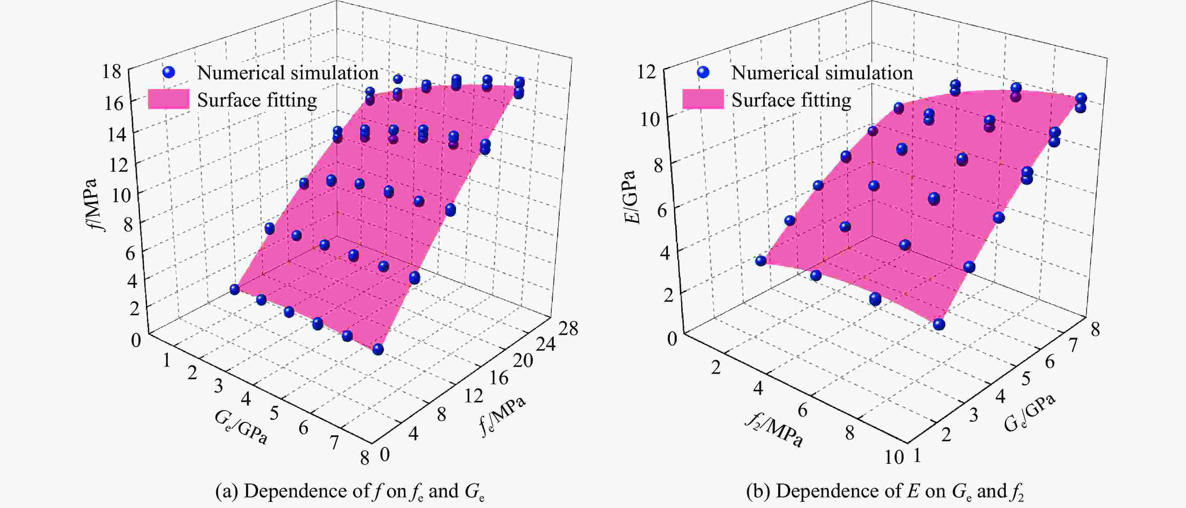
图 14 砌体单轴压缩强度和弹性模量的模拟结果和曲面拟合
Figure 14. Simulated results and surface fitting of uniaxial compressive strength and elastic modulus of masonry
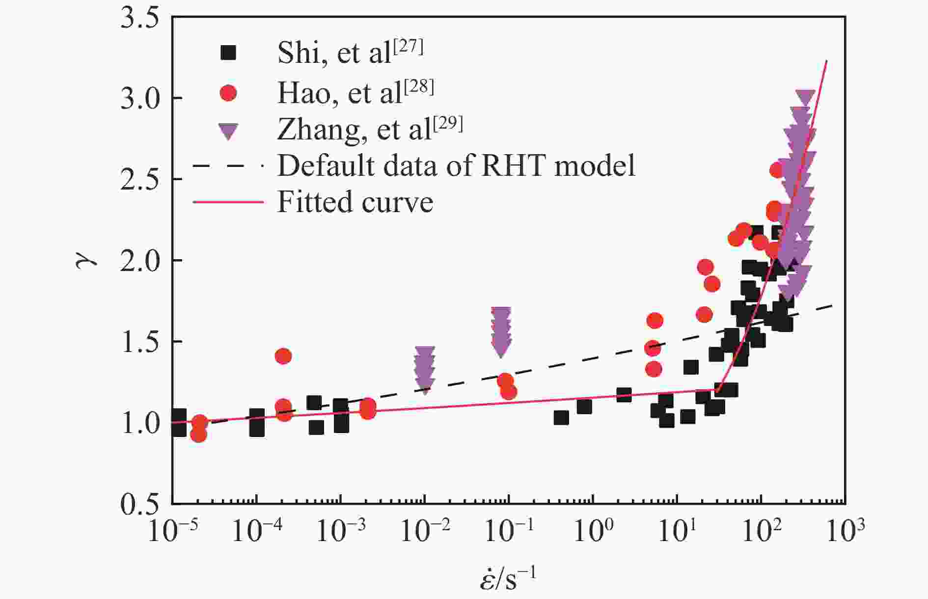
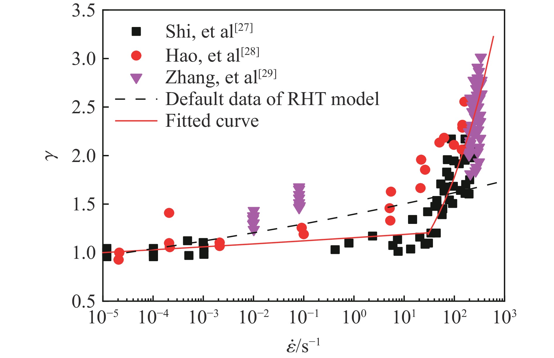
图 15 不同应变率下黏土砖的压缩动态增强因子
Figure 15. Dynamic increase factors of compressive strength of clay brick at different strain rates
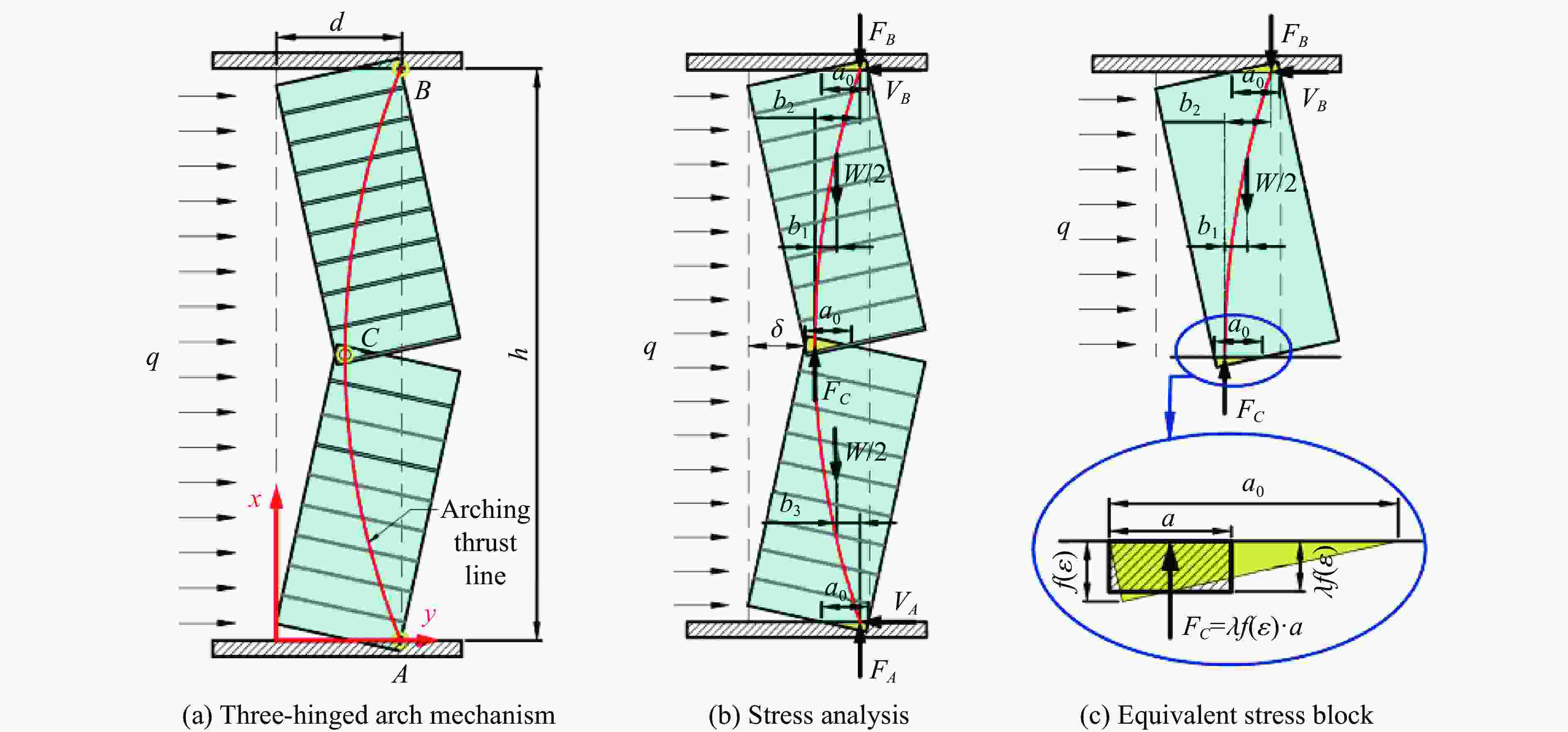
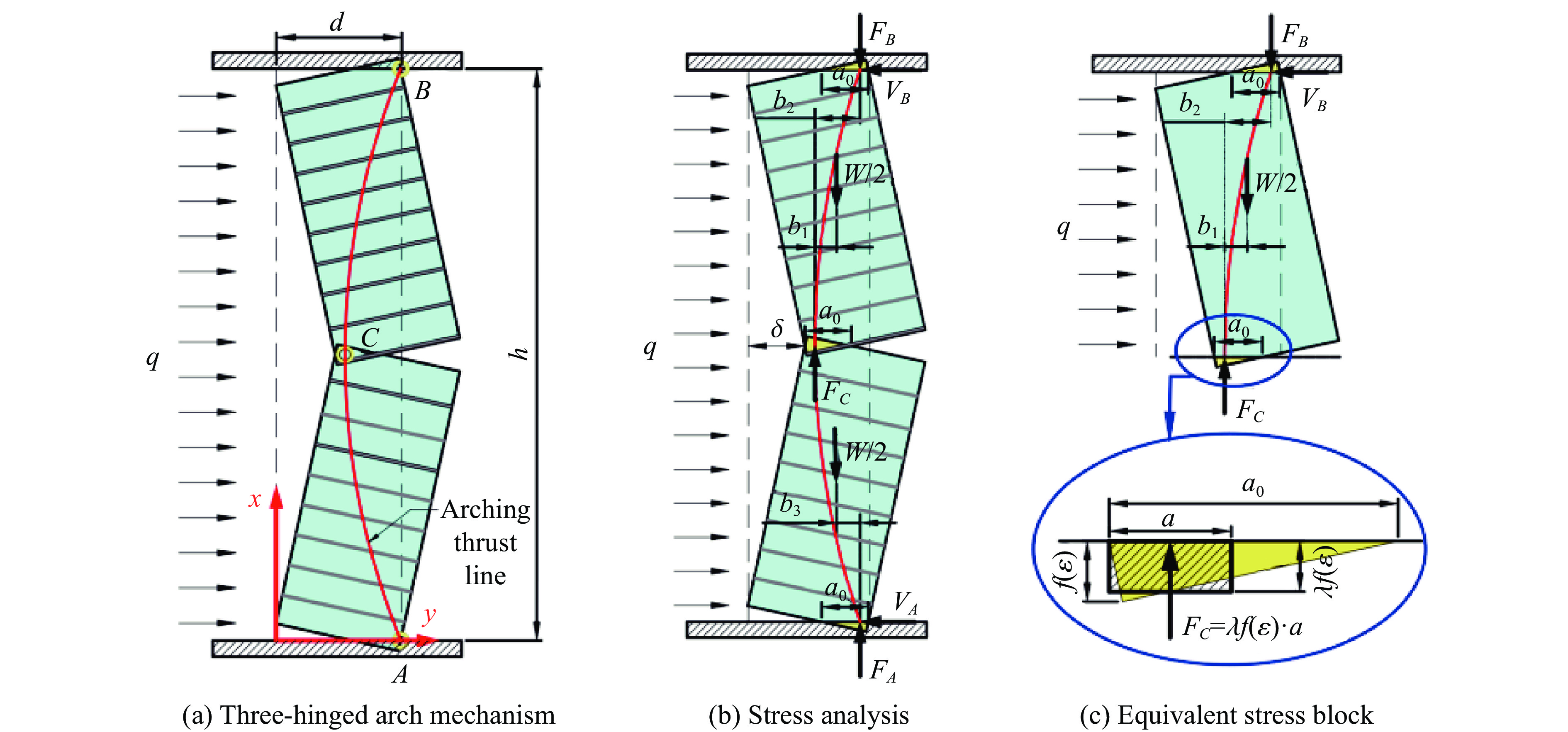
图 16 中间高度开裂后单向填充墙的变形模式和受力分析
Figure 16. Deformation mode and stress analysis of one-way masonry infilled wall after crack at mid-height
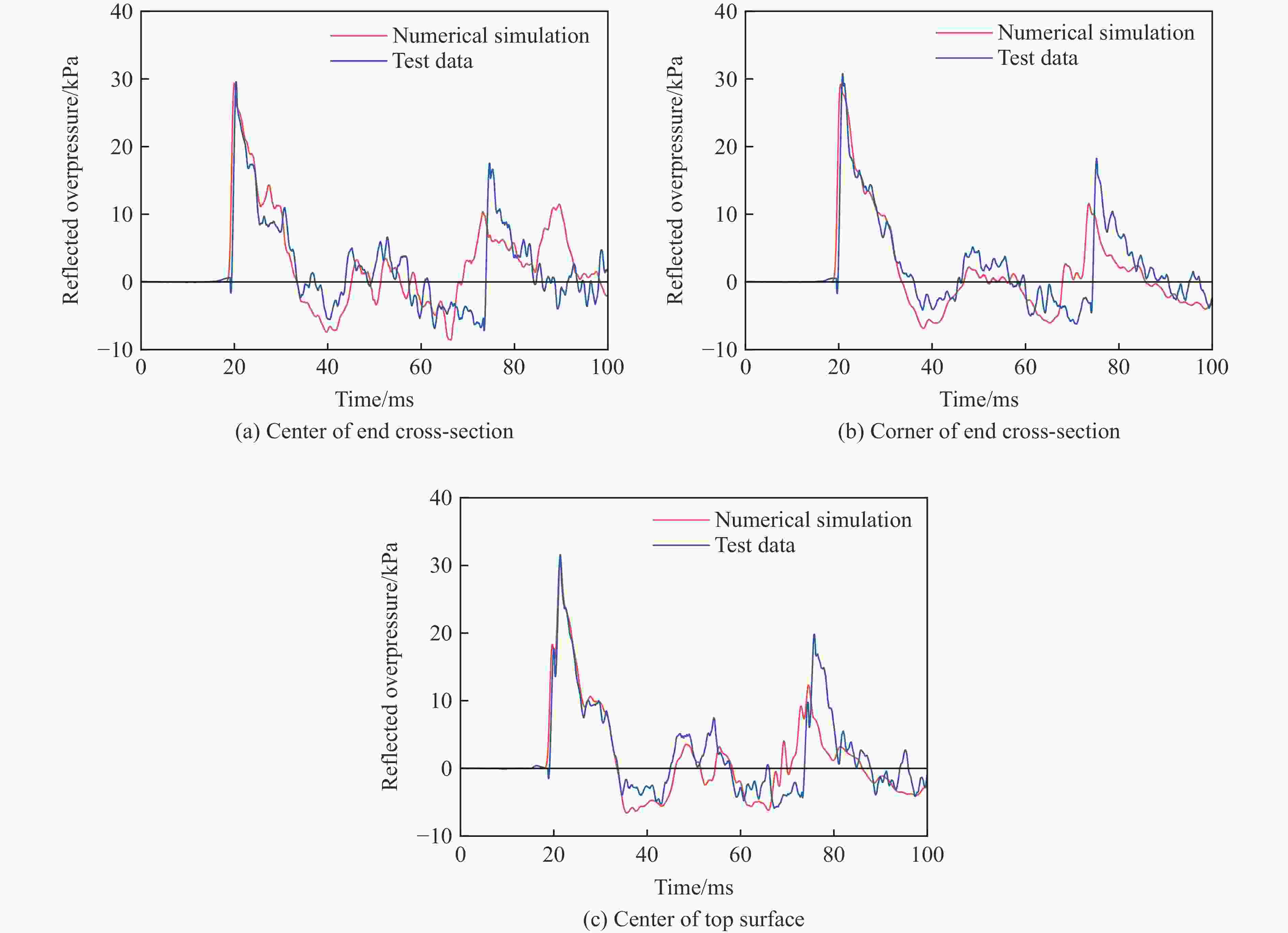
图 17 激波管荷载的数值模拟和试验结果对比
Figure 17. Comparisons of simulated and test loads of shock tube
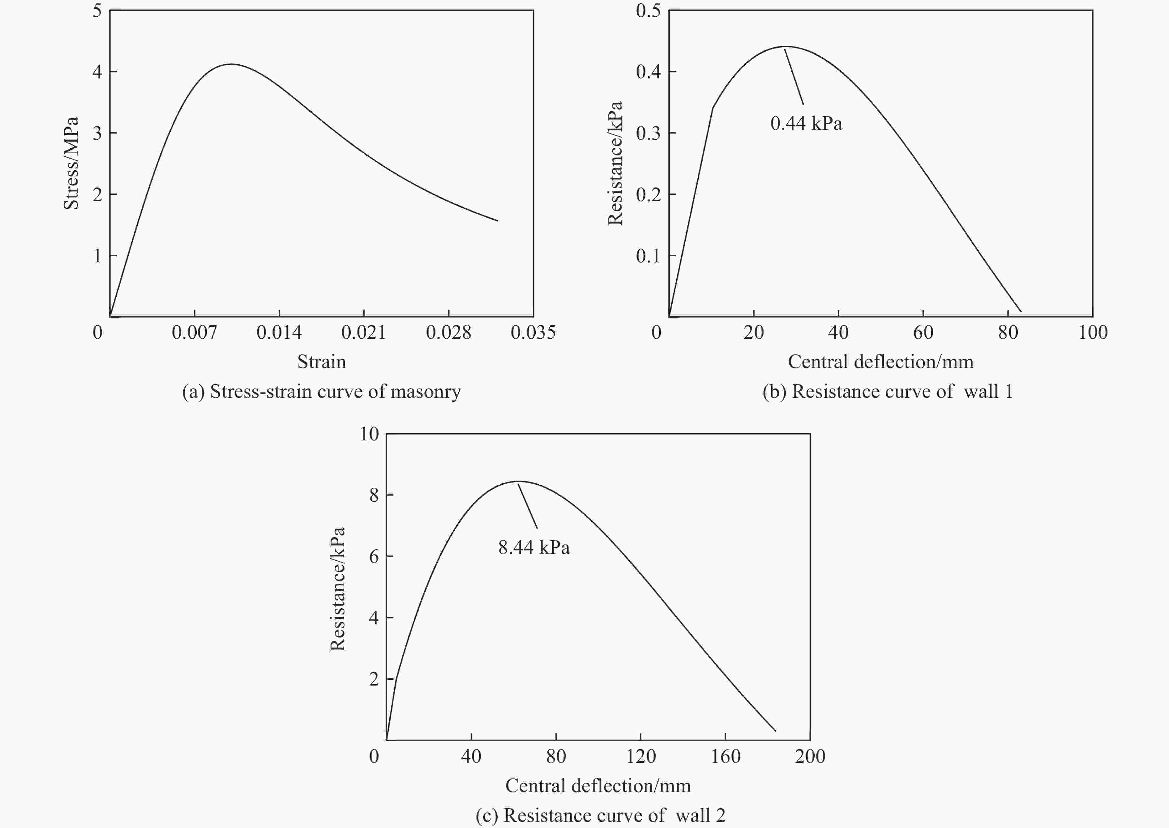
图 20 砌体单轴压缩特性和墙体抗力曲线
Figure 20. Uniaxial compressive property of masonry and resistance curves of walls
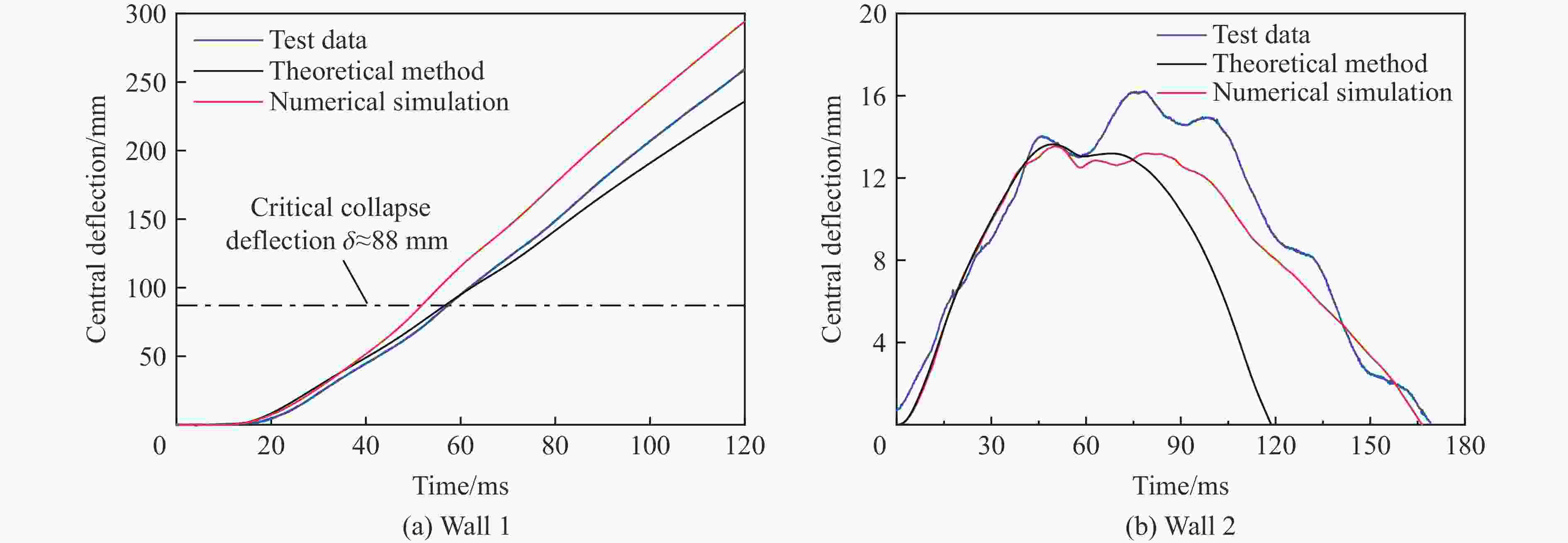
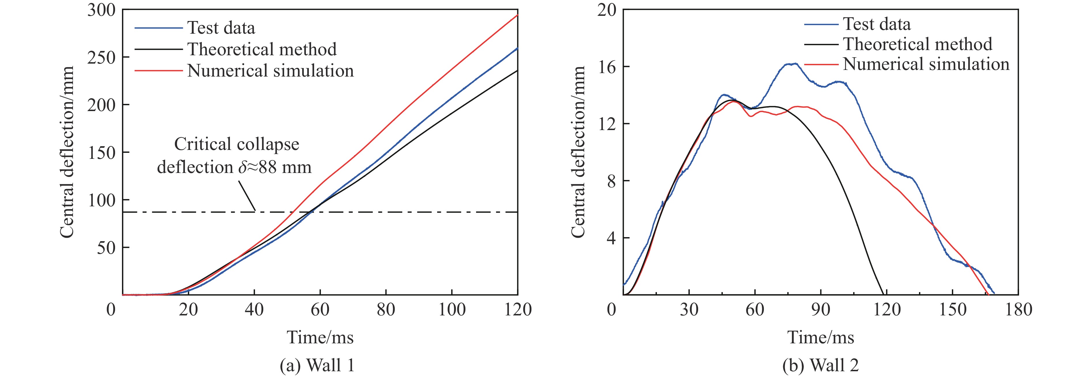
图 21 墙体中心点挠度时程预测结果和试验数据对比
Figure 21. Comparisons of predicted and test central deflection-time histories of the walls 1 and 2
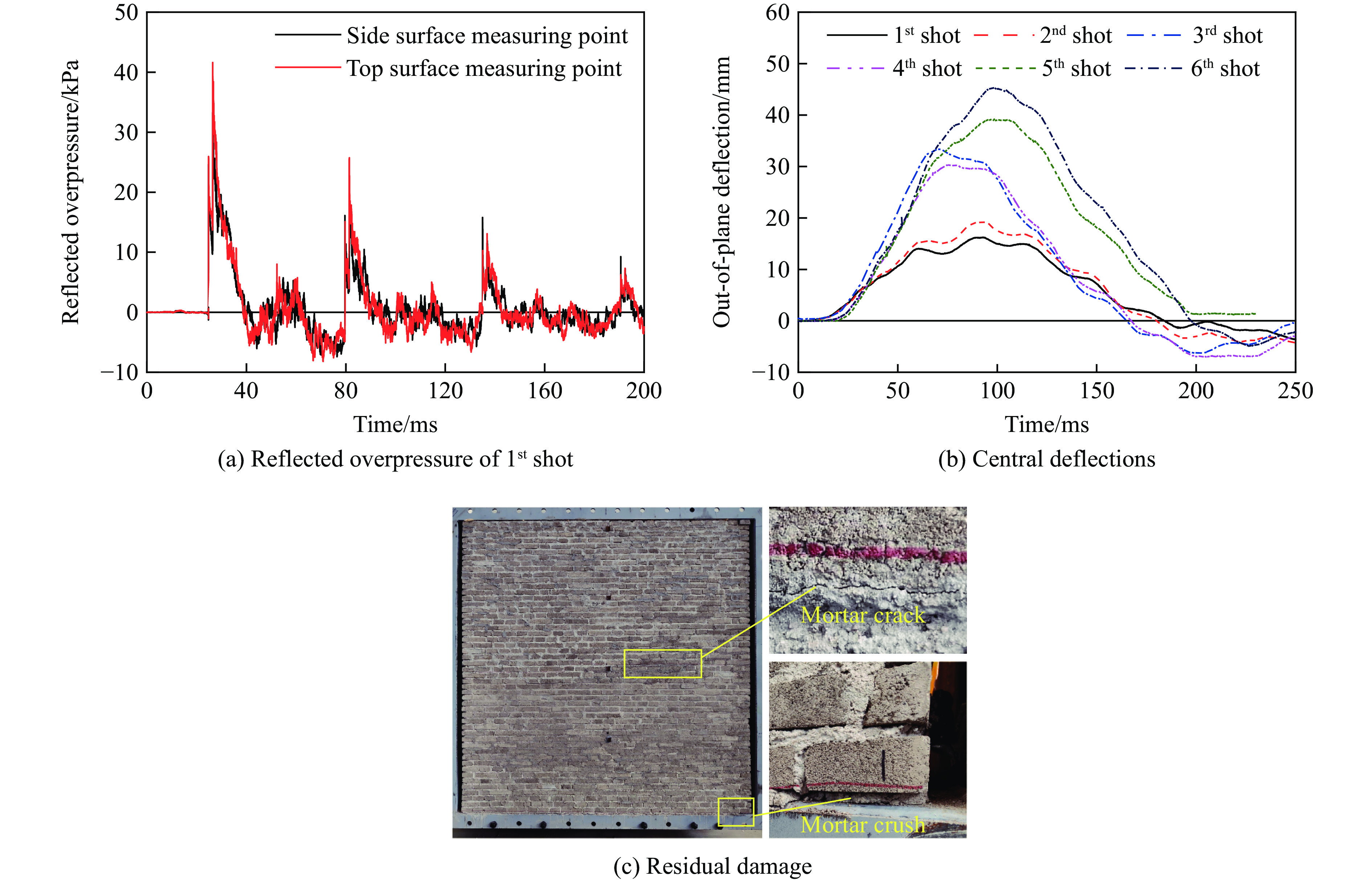
表 1 墙体2的试验结果
Table 1. Test results of the wall 2
试验编号 平均峰值超压/kPa 平均正压持时/ms 中心挠度/mm 累积损伤 峰值 残余 第1炮次 37.5 14.0 16.7 0.8 背爆面中间高度砂浆缝开裂 第2炮次 36.9 14.8 19.7 0.3 裂缝未进一步扩展 第3炮次 62.2 15.1 34.1 2.6 迎爆面中间高度砂浆缝开裂 第4炮次 58.7 14.8 30.4 0.8 裂缝未进一步扩展 第5炮次 63.9 15.5 39.1 2.4 墙体背爆面顶、底端砂浆局部压碎 第6炮次 63.1 15.2 45.4 1.7 墙体破坏未进一步扩展  下载: 导出CSV
表 2 空气的材料参数
Table 2. Material parameters of air
空气类型 初始压强/MPa 初始密度/(kg·m−3) 体积内能/(MJ·m−3) 常压空气 0.1 1.29 0.25 压缩空气 0.1N 1.29N 0.25N
下载: 导出CSV
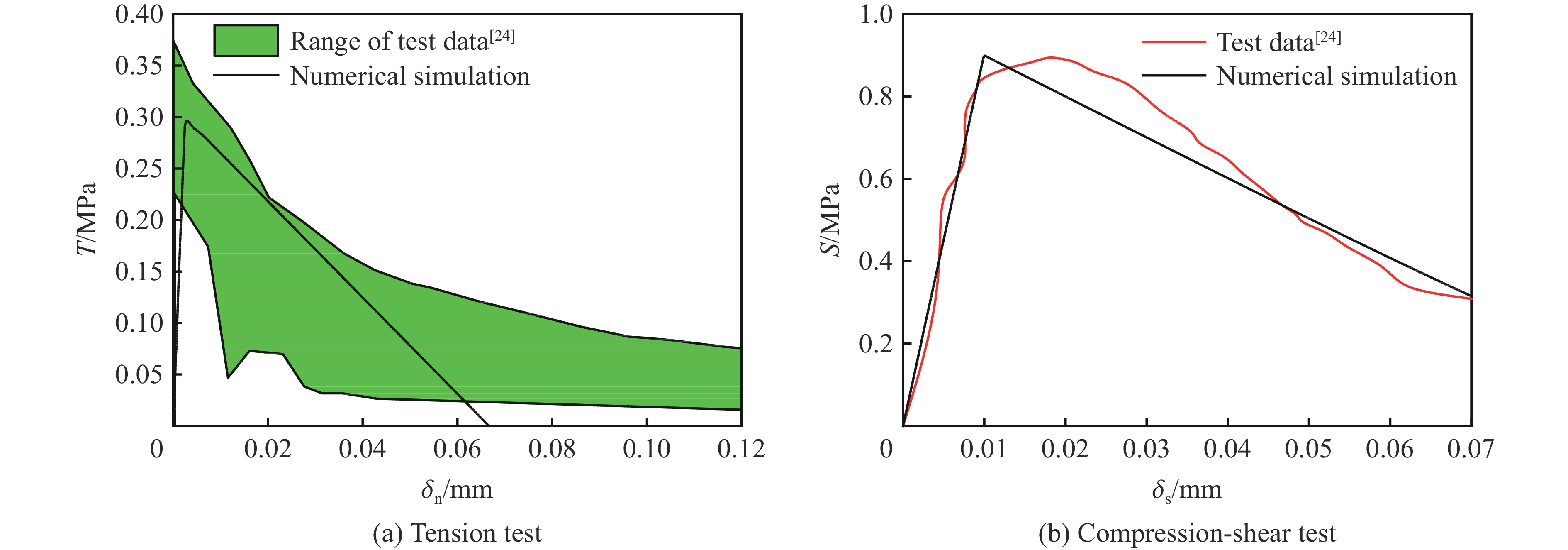
表 3 内聚力接触模型参数
Table 3. Parameters of the cohesive contact model
ks/(MPa·mm−1) kn/(MPa·mm−1) T/MPa S/MPa GI/(MPa·mm) GII/(MPa·mm) 108 250 0.3 0.9 0.01 0.045
下载: 导出CSV
表 4 扩展砖块的RHT材料模型参数
Table 4. RHT material model parameters of expanded masonry block
类别 参数 解释 取值 来源 状态方程参数 α0 初始孔隙度 1.32 文献[12] PE 破碎压力 40 MPa 文献[12] PC 密实压力 2 500 MPa 文献[12] ψ 指数 3 文献[12] Γ Grüneisen系数 0.0289 文献[12] A1 Hugoniot参数 13 GPa — A2 Hugoniot参数 39.58 GPa — A3 Hugoniot参数 9.04 GPa — B0 参数 1.22 文献[25] B1 参数 1.22 文献[25] T1 参数 13 GPa — T2 参数 0 文献[25] 强度面方程参数 fe 单轴压缩强度 式(10) Ge 剪切模量 式(10) $f_{\text{t}}^{\text{*}}$ 拉伸强度与压缩强度的比 0.1 — $f_{\text{s}}^{\text{*}}$ 剪切强度与压缩强度的比 0.2 — $ g_{\text{c}}^{\text{*}} $ 压缩屈服比 0.53 — $g_{\text{t}}^{\text{*}}$ 拉伸屈服比 0.7 — $\xi $ 剪切模量衰减系数 0.9 — A 失效强度面参数 1.6 — 强度面方程参数 n 失效强度面参数 0.61 — Q0 罗德角参数 0.6805 — B 罗德角参数 0.0105 — Af 残余强度面参数 1.6 — nf 残余强度面参数 0.61 — D1 损伤参数 0.04 — D2 损伤参数 1.0 — 应变率增强因子参数 $ \dot \varepsilon _{\text{0}}^{\text{c}} $ 参考应变率 1×10⁻⁵ s−1 式(12) $ \dot \varepsilon _{\text{p}}^{\text{c}} $ 转换应变率 30 s−1 式(12) βc 指数 0.01244 式(12) 注:表中符号“—”表示该参数取值为ANSYS/LS-DYNA软件中RHT材料模型的自动计算的默认值。
下载: 导出CSV
表 5 内聚力接触和RHT模型关键参数
Table 5. Key parameters of the cohesive contact and the RHT model
kn/(MPa·mm−1) ks/(MPa·mm−1) T/MPa S/MPa GI/(N·mm−1) GII/(N·mm−1) fe/MPa Ge/GPa 1460 630 0.45 0.79 0.015 0.040 5.57 3.5
下载: 导出CSV
-
[1] THOMPSON D, BROWN S, MALLONEE S, et al. Fatal and non-fatal injuries among U. S. air force personnel resulting from the terrorist bombing of the Khobar towers [J]. The Journal of Trauma: Injury, Infection, and Critical Care, 2004, 57(2): 208–215. DOI: 10.1097/01.TA.0000142672.99660.80. [2] VARMA R K, TOMAR C P S, PARKASH S, et al. Damage to brick masonry panel walls under high explosive detonations [C]//ASME PVP Conference. New York, USA: American Society of Mechanical Engineers, 1997, 351: 207–216. [3] 范俊余, 方秦, 陈力, 等. 砌体填充墙的抗爆性能 [J]. 爆炸与冲击, 2014, 34(1): 59–66. DOI: 10.11883/1001-1455(2014)01-0059-08.FAN J Y, FANG Q, CHEN L, et al. Anti-blast properties of masonry infill walls [J]. Explosion and Shock Waves, 2014, 34(1): 59–66. DOI: 10.11883/1001-1455(2014)01-0059-08. [4] 王军国. 喷涂聚脲加固粘土砖砌体抗动载性能试验研究及数值分析 [D]. 合肥: 中国科学技术大学, 2017.WANG J G. Experimental and numerical investigation of clay brick masonry walls strengthened with Spary polyurea elastomer under blast loads [D]. Heifei, Anhui, China: University of Science and Technology of China, 2017. [5] DAVIDSON J S, HOEMANN J M, SHULL J S, et al. Full-scale experimental evaluation of partially grouted minimally reinforced concrete masonry unit (CMU) walls against blast demands [R]. Auburn, USA: Department of Civil Engineering, Auburn University, 2010. [6] YU Q, ZENG D, XU X, et al. Experimental and numerical investigation of polymer-reinforced and normal autoclaved aerated concrete masonry walls under large TNT explosive loads [J]. International Journal of Impact Engineering, 2022, 164: 104188. DOI: 10.1016/j.ijimpeng.2022.104188. [7] KEYS R A, CLUBLEY S K. Experimental analysis of debris distribution of masonry panels subjected to long duration blast loading [J]. Engineering Structures, 2017, 130: 229–241. DOI: 10.1016/j.engstruct.2016.10.054. [8] CIORNEI L. Performance of polyurea retrofitted unreinforced concrete masonry walls under blast loading [D]. Ottawa: University of Ottawa (Canada), 2012. DOI: 10.20381/ruor-5935. [9] EDRI I E, YANKELEVSKY D Z, REMENNIKOV A M, et al. Combined experimental and theoretical study on the blast response of arching masonry walls [J]. International Journal of Impact Engineering, 2023, 174: 104495. DOI: 10.1016/j.ijimpeng.2023.104495. [10] WEI X Y, STEWART M G. Model validation and parametric study on the blast response of unreinforced brick masonry walls [J]. International Journal of Impact Engineering, 2010, 37(11): 1150–1159. DOI: 10.1016/j.ijimpeng.2010.04.003. [11] HAO H. Numerical modelling of masonry wall response to blast loads [J]. Australian Journal of Structural Engineering, 2009, 10(1): 37–52. DOI: 10.1080/13287982.2009.11465031. [12] MICHALOUDIS G, GEBBEKEN N. Modeling masonry walls under far-field and contact detonations [J]. International Journal of Impact Engineering, 2019, 123: 84–97. DOI: 10.1016/j.ijimpeng.2018.09.019. [13] EDRI I E, YANKELEVSKY D Z. An analytical model for the out-of-plane response of URM walls to different lateral static loads [J]. Engineering Structures, 2017, 136: 194–209. DOI: 10.1016/j.engstruct.2017.01.001. [14] MORADI L G, DAVIDSON J S, DINAN R J. Resistance of membrane retrofit concrete masonry walls to lateral pressure [J]. Journal of Performance of Constructed Facilities, 2008, 22(3): 131–142. DOI: 10.1061/(ASCE)0887-3828(2008)22:3(131). [15] 陈德, 吴昊, 方秦. 爆炸荷载作用下单向砌体填充墙动态响应计算方法 [J/OL]. 建筑结构学报, 2022 (2022-09-09)[2023-04-23]. DOI: 10.14006/j.jzjgxb.2022.0130.CHEN D, WU H, FANG Q. Dynamic responses calculation method of one-way masonry infill wall under blast loadings [J/OL]. Journal of Building Structures, 2022 (2022-09-09)[2023-04-23]. DOI: 10.14006/j.jzjgxb.2022.0130. [16] SLAWSON T R. Wall response to air blast loads: the wall analysis code (WAC) [R]. Vicksburg, MS, USA: US Army Engineering and Development Center, 1995. [17] Protect Design Center. Methodology manual for the single-degree-of freedom blast effects design spreadsheets (SBEDS) [M]. USA: United States Army Corps of Engineers, 2008. [18] 中华人民共和国住房和城乡建设部. 砌体结构设计规范: GB 50003—2011 [S]. 北京: 中国建筑工业出版社, 2012. [19] United States Army Corps of Engineers. Structures to resist the effects of accidental explosions: UFC 3-340-02 [S]. Washington, USA: Department of the Army, the Navy and the Air Force, 2008. [20] CHEN D, WU H, FANG Q. Simplified micro-model for brick masonry walls under out-of-plane quasi-static and blast loadings [J]. International Journal of Impact Engineering, 2023, 174: 104529. DOI: 10.1016/j.ijimpeng.2023.104529. [21] LOURENÇO P B, ROTS J G, BLAAUWENDRAAD J. Continuum model for masonry: parameter estimation and validation [J]. Journal of Structural Engineering, 1998, 124(6): 642–652. DOI: 10.1061/(ASCE)0733-9445(1998)124:6(642). [22] 刘桂秋. 砌体结构基本受力性能的研究 [D]. 长沙: 湖南大学, 2005.LIU G Q. The research on the basic mechanical behavior of masonry structure [D]. Changsha, Hunan, China: Hunan University, 2005. [23] 蒋济同, 周新智. 基于分离式建模的砌体墙力学性能有限元分析参数探讨 [J]. 建筑结构, 2019, 49(S1): 640–644. DOI: 10.19701/j.jzjg.2019.S1.133.JIANG J T, ZHOU X Z. Discussion on parameters in finite element analysis of mechanical properties of masonry wall based on separation modeling [J]. Building Structure, 2019, 49(S1): 640–644. DOI: 10.19701/j.jzjg.2019.S1.133. [24] TNO B, VAN DER PLUIJM R. Out-of-plane bending of masonry behaviour and strength [D]. Eindhoven, the Netherlands: Eindhoven University of Technology, 1999. [25] SAUER C, HEINE A, BAGUSAT F, et al. Ballistic impact on fired clay masonry bricks [J]. International Journal of Protective Structures, 2020, 11(3): 304–318. DOI: 10.1177/2041419619893708. [26] 中华人民共和国住房和城乡建设部. 砌体基本力学性能试验方法标准: GB/T 50129—2011 [S]. 北京: 中国建筑工业出版社, 2011. [27] SHI Y C, WANG N, LI Z X, et al. Experimental studies on the dynamic compressive and tensile strength of clay brick under high strain rates [J]. Construction and Building Materials, 2021, 272: 121908. DOI: 10.1016/j.conbuildmat.2020.121908. [28] HAO H, TARASOV B G. Experimental study of dynamic material properties of clay brick and mortar at different strain rates [J]. Australian Journal of Structural Engineering, 2008, 8(2): 117–132. DOI: 10.1080/13287982.2008.11464992. [29] ZHANG X H, CHIU Y W, HAO H, et al. Dynamic compressive material properties of clay bricks at different strain rates [J]. Construction and Building Materials, 2018, 192: 754–767. DOI: 10.1016/j.conbuildmat.2018.10.150. [30] 杨卫忠. 砌体受压本构关系模型 [J]. 建筑结构, 2008, 38(10): 80–82. DOI: 10.19701/j.jzjg.2008.10.027.YANG W Z. Constitutive relationship model for masonry materials in compression [J]. Building Structure, 2008, 38(10): 80–82. DOI: 10.19701/j.jzjg.2008.10.027. [31] 肖遥, 底欣欣, 黄河. 砖砌体单轴压缩与拉伸应力应变关系 [J]. 世界地震工程, 2019, 35(1): 210–219.XIAO Y, DI X X, HUANG H. Stress-strain relationships of brick masonry under uniaxial compression and tension [J]. World Earthquake Engineering, 2019, 35(1): 210–219. [32] BIGGS J M. Introduction to structural dynamics [M]. New York, USA: McGraw-Hill, 1964. -


计量
- 文章访问数: 592
- HTML全文浏览量: 170
- PDF下载量: 75
- 被引次数: 0