


Penetration resistance of ceramic/UHMWPE composite structures with porous titanium alloy sandwich layer
-
摘要: 陶瓷/纤维复合装甲的纤维背板由于其刚度较低,无法为陶瓷面板提供足够的支撑,削弱了陶瓷面板对弹丸的侵蚀作用。为了增强复合装甲的整体结构刚度,在陶瓷/纤维复合装甲中加入了金属夹芯层材料,通过试验和数值模拟研究了夹芯复合装甲对12.7 mm穿燃弹的抗弹性能。试验结果表明,穿燃弹弹芯表现出脆性断裂的失效模式,复合材料装甲表现出多种失效模式,包括夹芯层的花瓣形扩孔,UHMWPE (ultra-high molecular weight polyethylene)层压板的分层和凸起变形。建立了三维数值模型来分析整个弹道响应的演变,通过试验结果验证了模拟的准确性。模拟结果表明,12.7 mm穿燃弹的被甲会对陶瓷造成损伤,同时陶瓷会侵蚀弹芯的尖卵形头部,使弹芯头部变钝从而削弱弹芯对UHMWPE背板的侵彻能力。残余弹体的动能大部分由UHMWPE层吸收,UHMWPE层压板的失效模式会随着层数的增加由剪切失效转变为拉伸失效占主导地位。此外,作为夹芯层的多孔TC4板能够为陶瓷面板提供支撑,提高陶瓷面板的吸能效果以及弹体的侵蚀作用,并且12 mm孔径的TC4夹芯层能够提供更大的刚度支撑,使整体复合结构的吸能效率提升10%。
-
关键词:
- 陶瓷复合装甲 /
- 多孔夹芯层 /
- UHMWPE /
- 12.7 mm穿燃弹
Abstract: The fiber back plate in ceramic/fiber composite armor cannot provide sufficient support for the ceramic panel due to its low stiffness, which weakens the erosion effect of the ceramic panel on the projectile. In order to enhance the overall structural stiffness of composite armor, a metal sandwich layer material was added to the ceramic/fiber composite armor. The ballistic performance of the sandwich composite armor against 12.7-mm incendiary projectiles was studied through experiments and numerical simulations. The experimental results indicate that the core of the penetrator exhibits a brittle fracture failure mode, while composite armor exhibits multiple failure modes, including petal-shaped expansion of the sandwich layer, delamination and protrusion deformation of the UHMWPE (ultra-high molecular weight polyethylene) laminate. A three-dimensional numerical model was established to analyze the evolution of the entire ballistic response, and the accuracy of the simulation was verified through experimental results. The simulation results indicate that the armor of the 12.7-mm penetrator will cause damage to the ceramic, which will erode the pointed oval head of the projectile core, making the core head blunt and weakening the penetration ability of the projectile core into the UHMWPE backing plate. Most of the kinetic energy of the residual projectile is absorbed by the UHMWPE layer, and the failure mode of the UHMWPE laminate will change from shear failure to tensile failure as the number of layers increases. In addition, as a sandwich layer, the porous TC4 board can provide support for the ceramic panel, increase the energy absorption of the ceramic panel and erosion of the projectile, and the 12-mm-pore-size TC4 sandwich layer can provide greater stiffness support, increase the energy absorption efficiency of the overall composite structure by 10%.-
Key words:
- ceramic composite armor /
- porous sandwich layer /
- UHMWPE /
- 12.7 mm armor piercing bullet
-
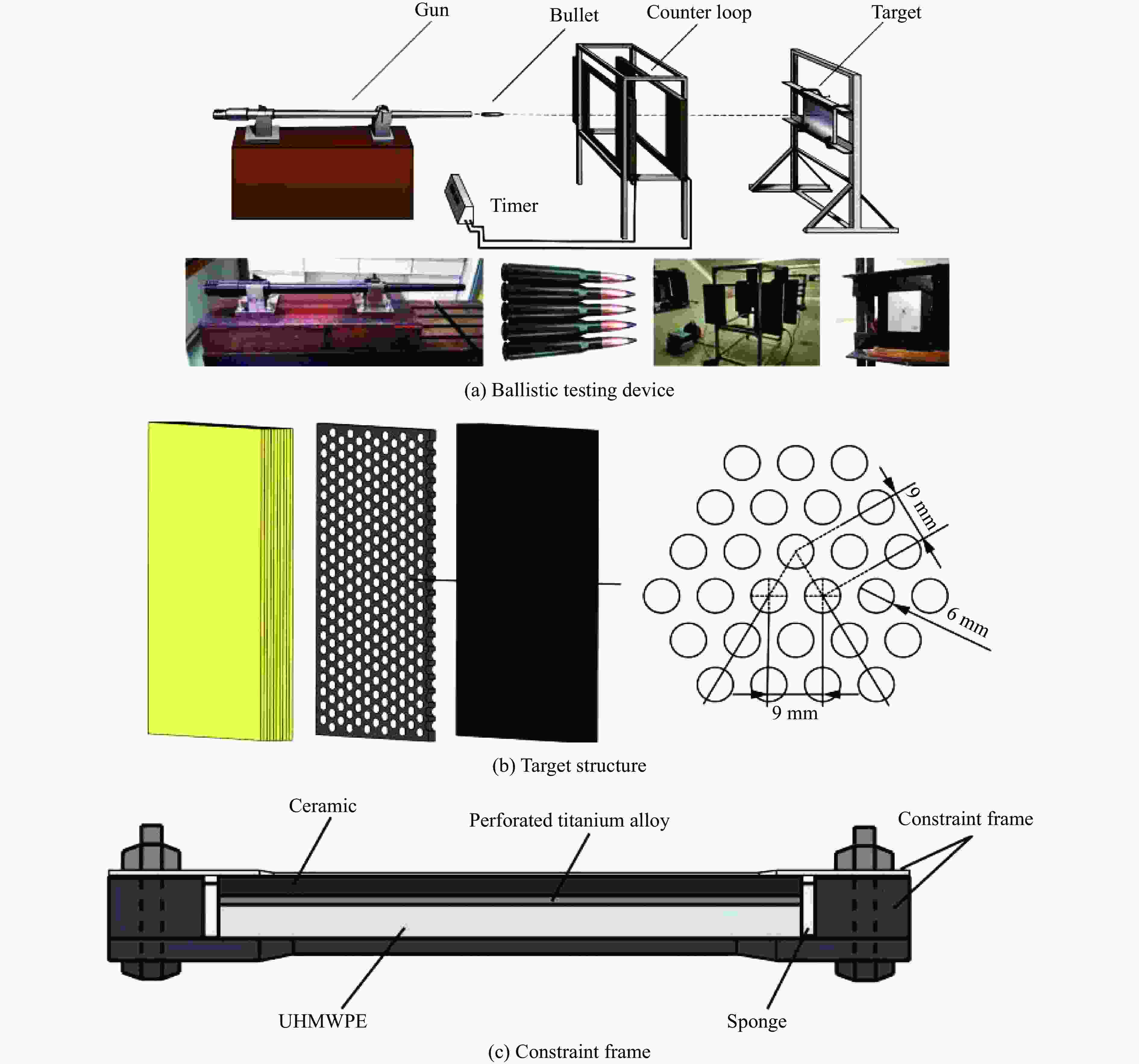
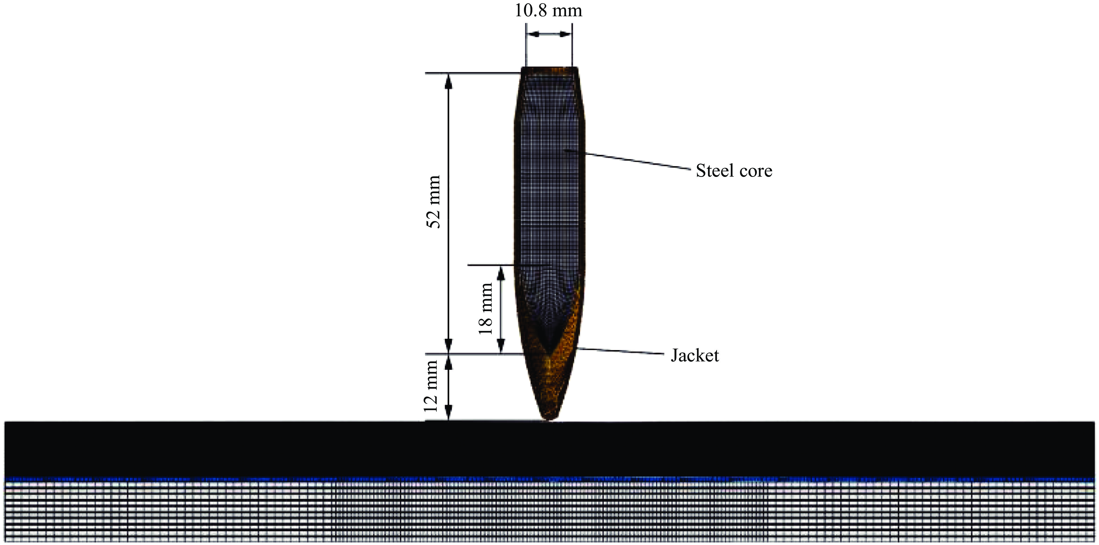
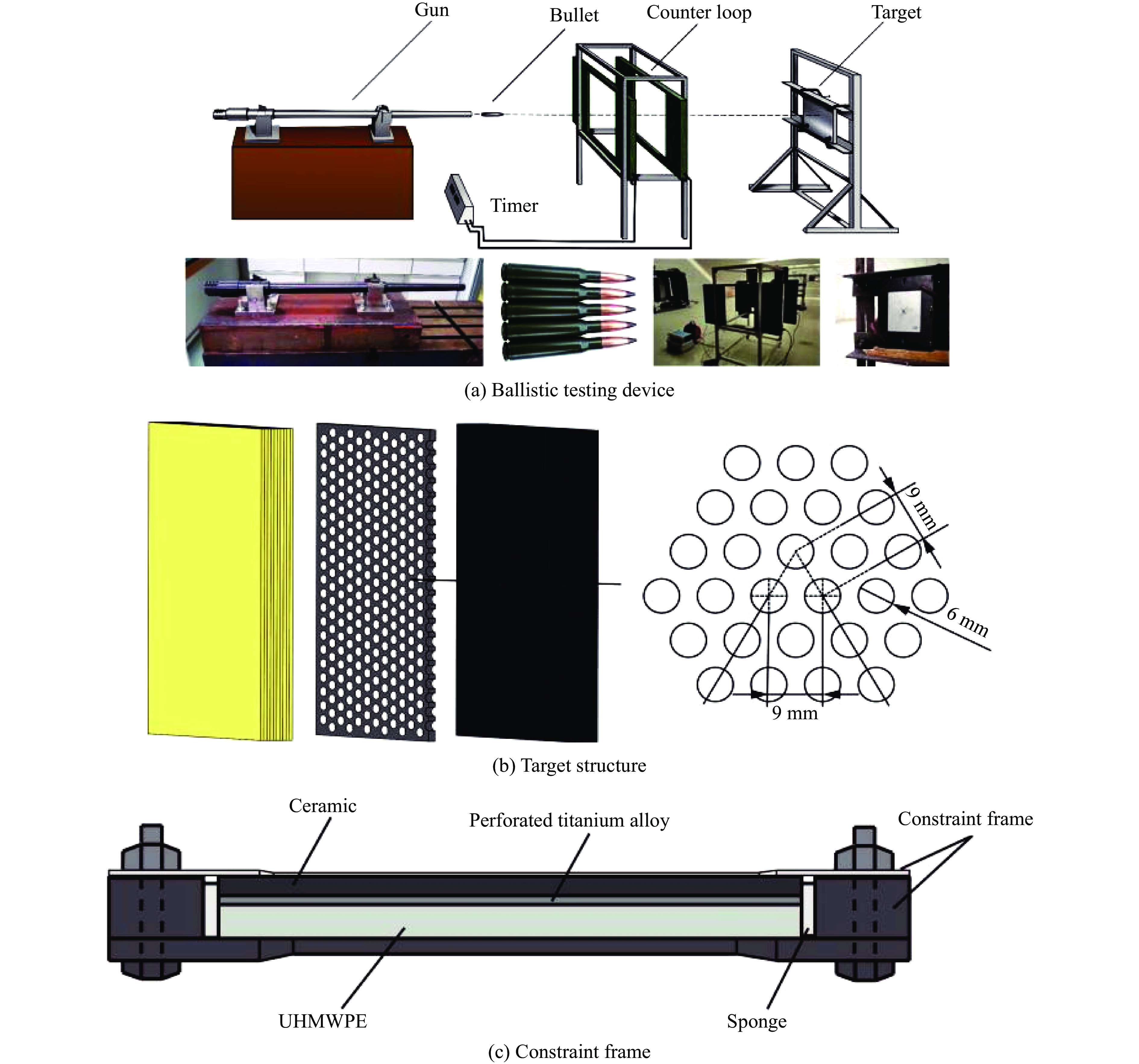
图 1 弹道试验装置及靶板结构示意图
Figure 1. Schematic diagrams of ballistic testing device and target structure
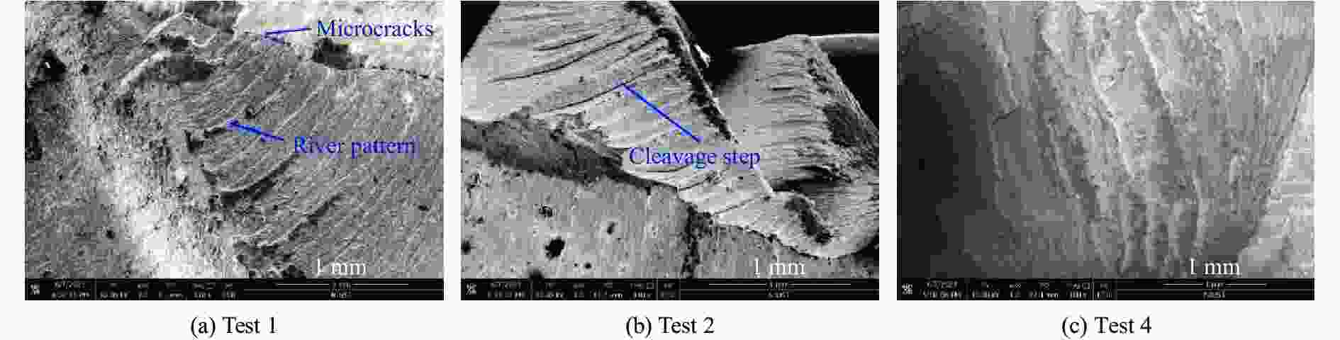
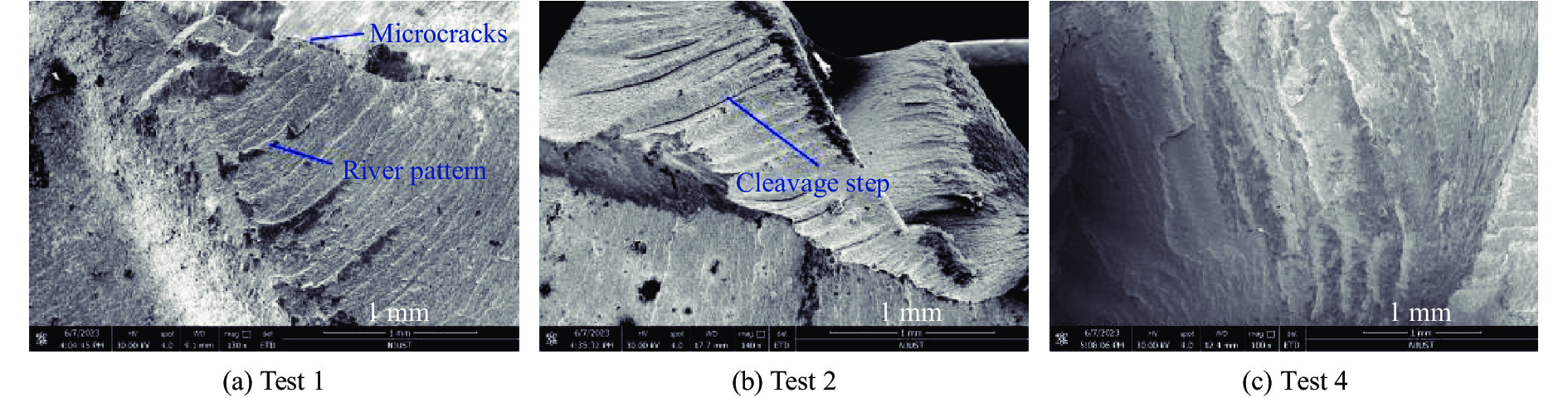
图 4 试验1~2和4的残余弹体断面SEM图像
Figure 4. SEM images of fracture surfaces of residual projectiles in tests 1, 2, and 4
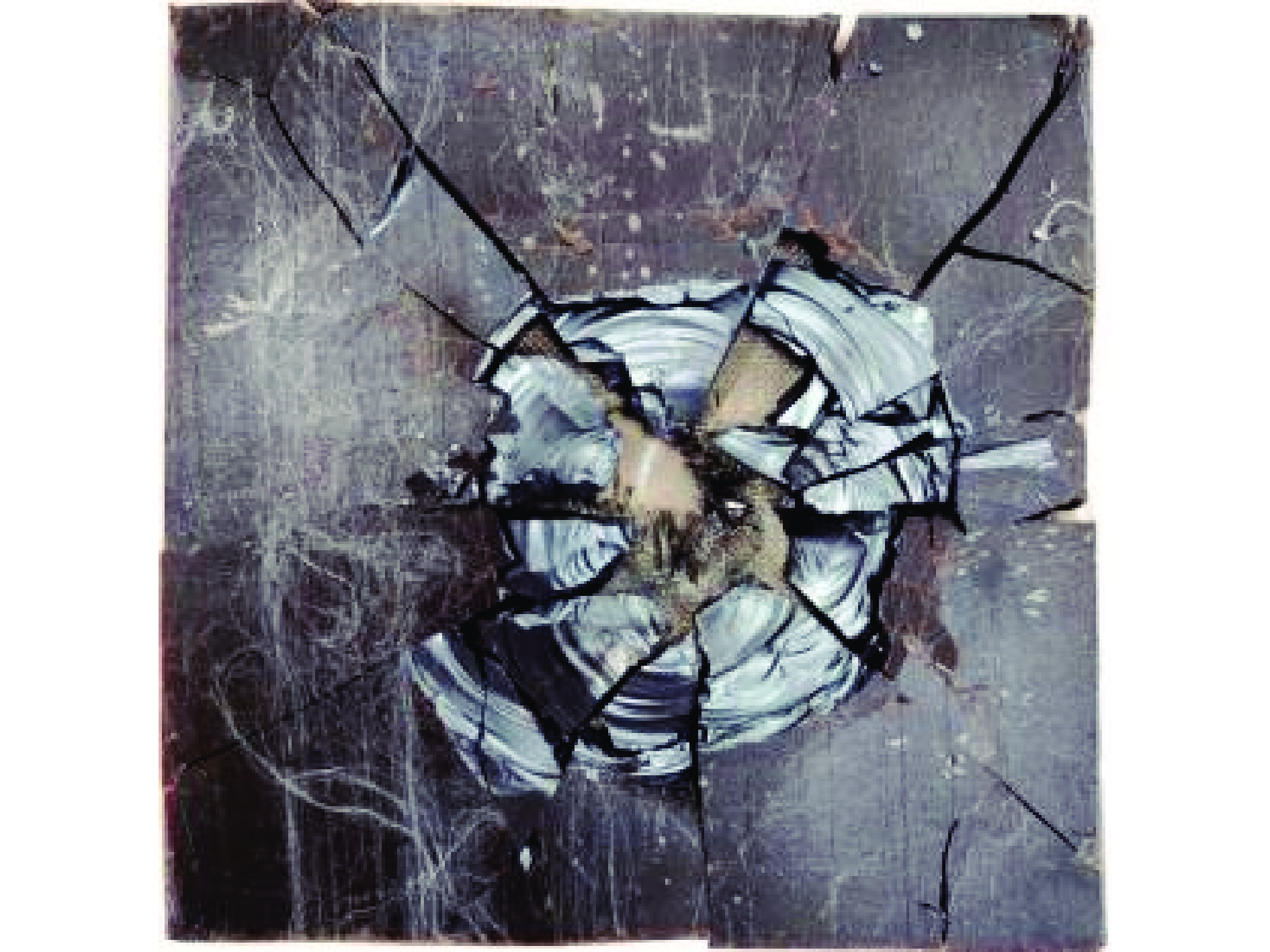
图 6 试验7双层结构中陶瓷的破坏形貌
Figure 6. Ceramic failure morphology in double-layer structure in test 7
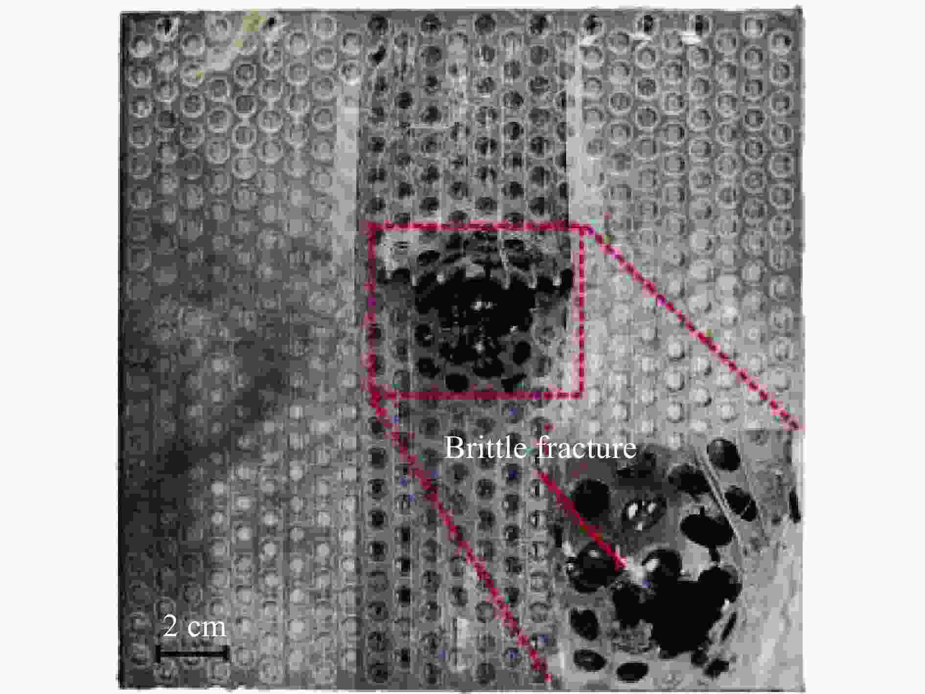
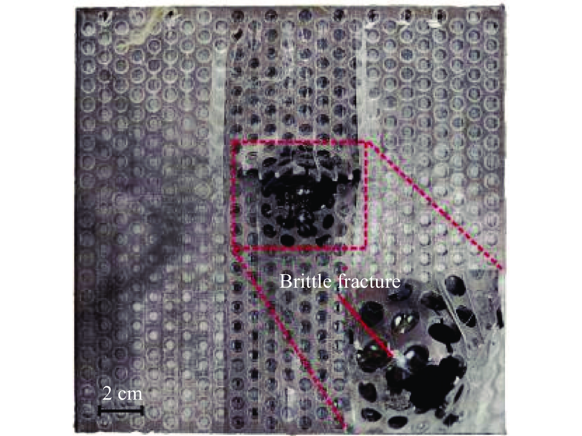
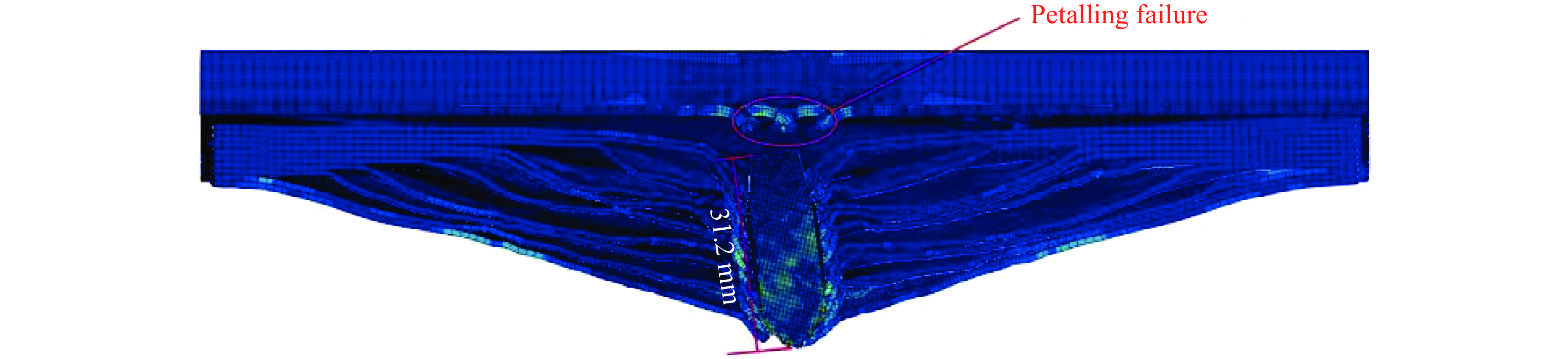
图 7 试验1多孔TC4夹芯层的破坏形貌
Figure 7. Failure morphology of porous TC4 sandwich layer in test 1
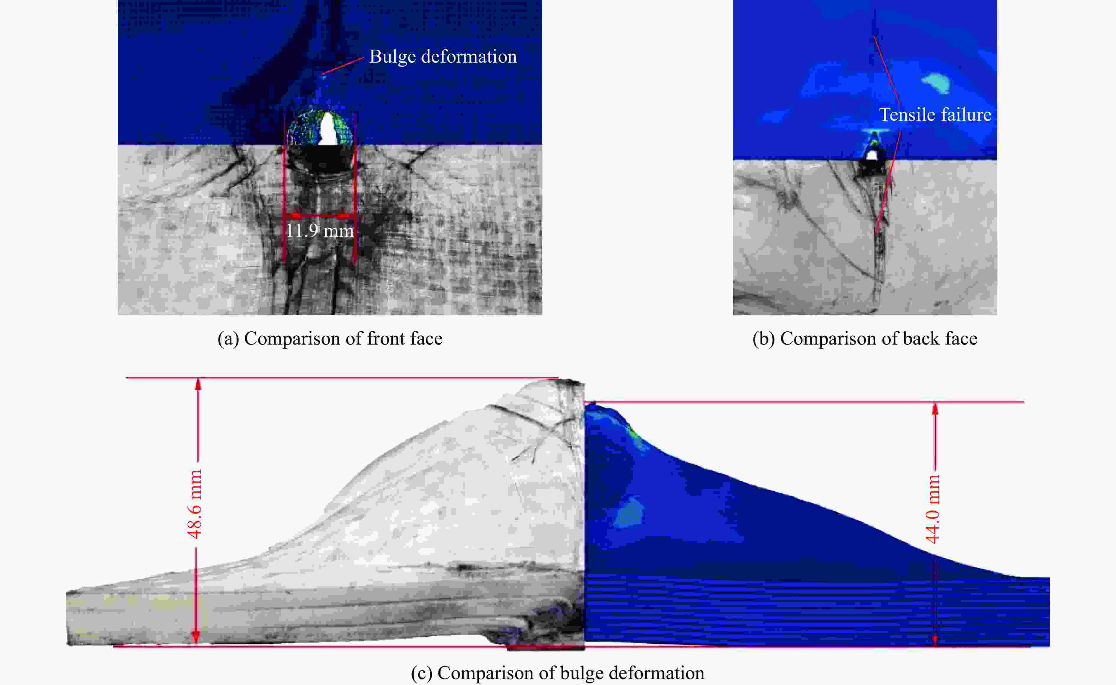
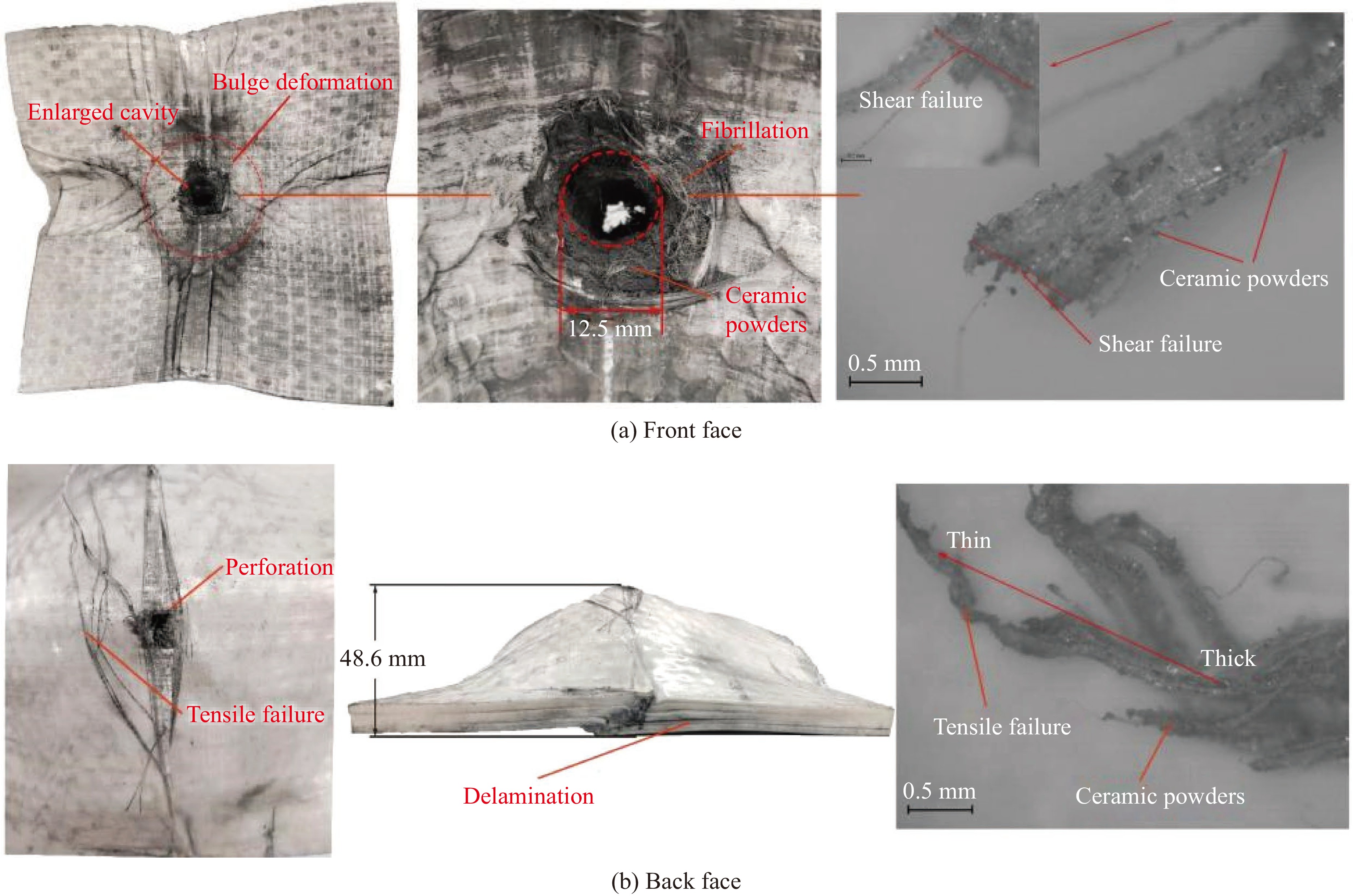
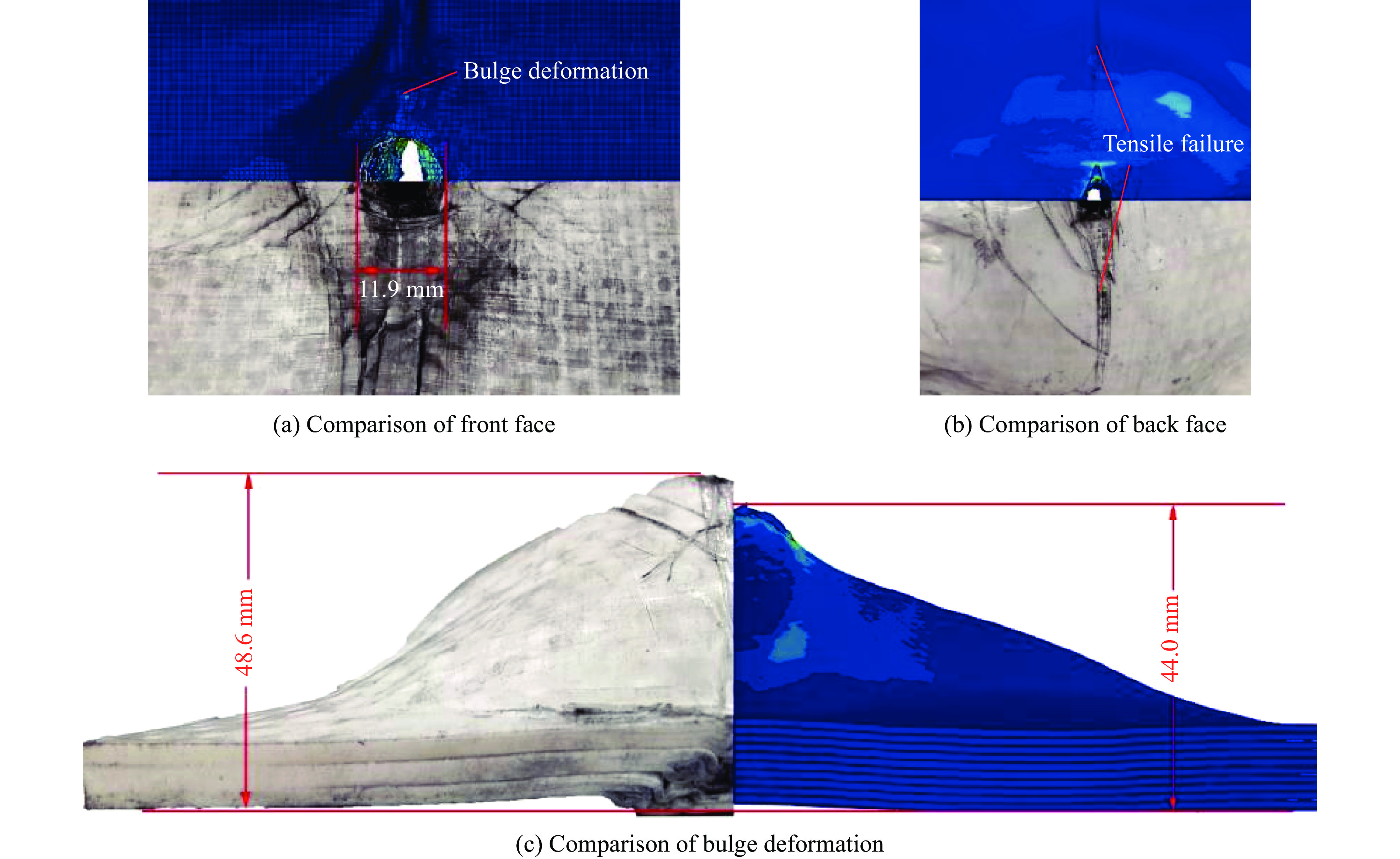
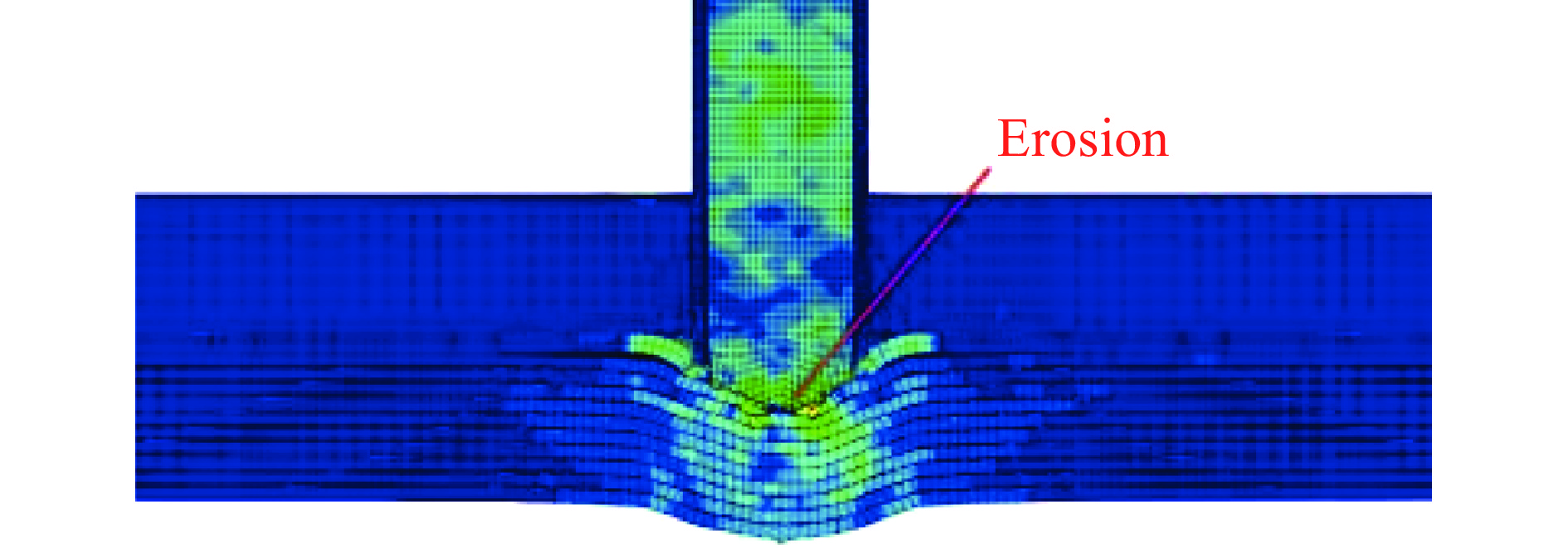
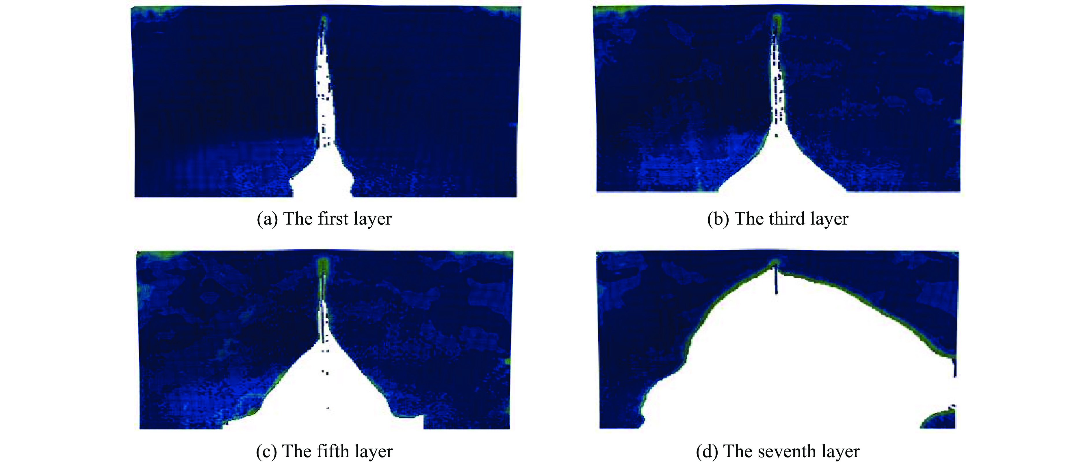
图 10 UHMWPE的失效形式的仿真和试验结果对比图
Figure 10. Comparison between simulation and experimental results of the failure mode of UHMWPE
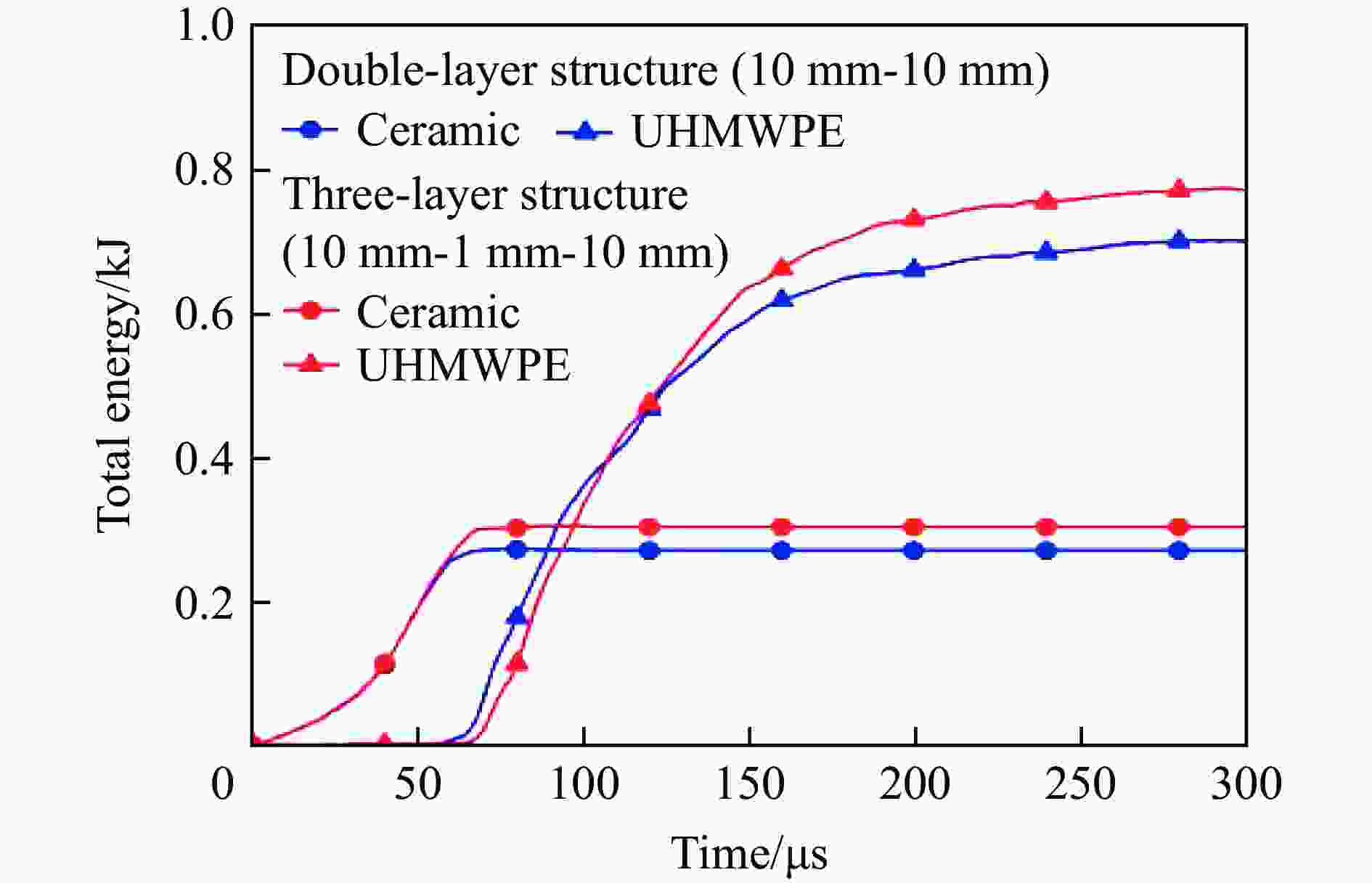
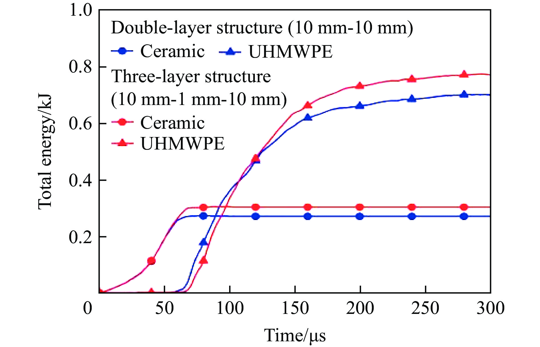
图 15 双层装甲结构与三层装甲结构能量吸收对比
Figure 15. Comparison of energy absorption between double-layer and three-layer armor structures
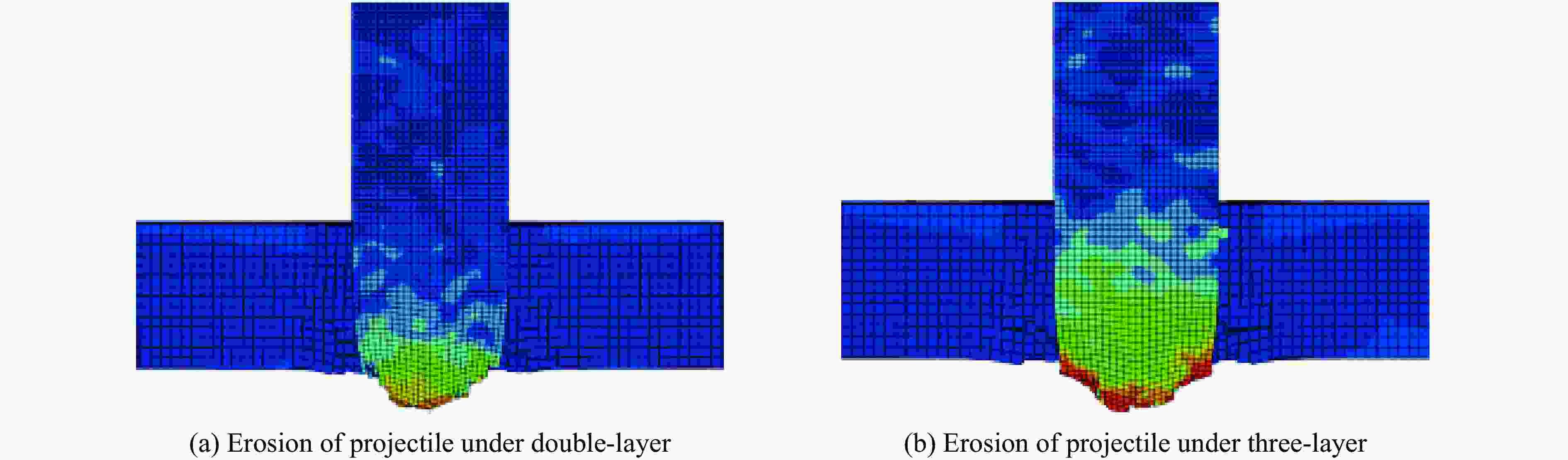
图 16 双层装甲结构和三层装甲结构中弹头侵蚀对比
Figure 16. Comparison of projectile erosion in double-layer and three-layer armor structures

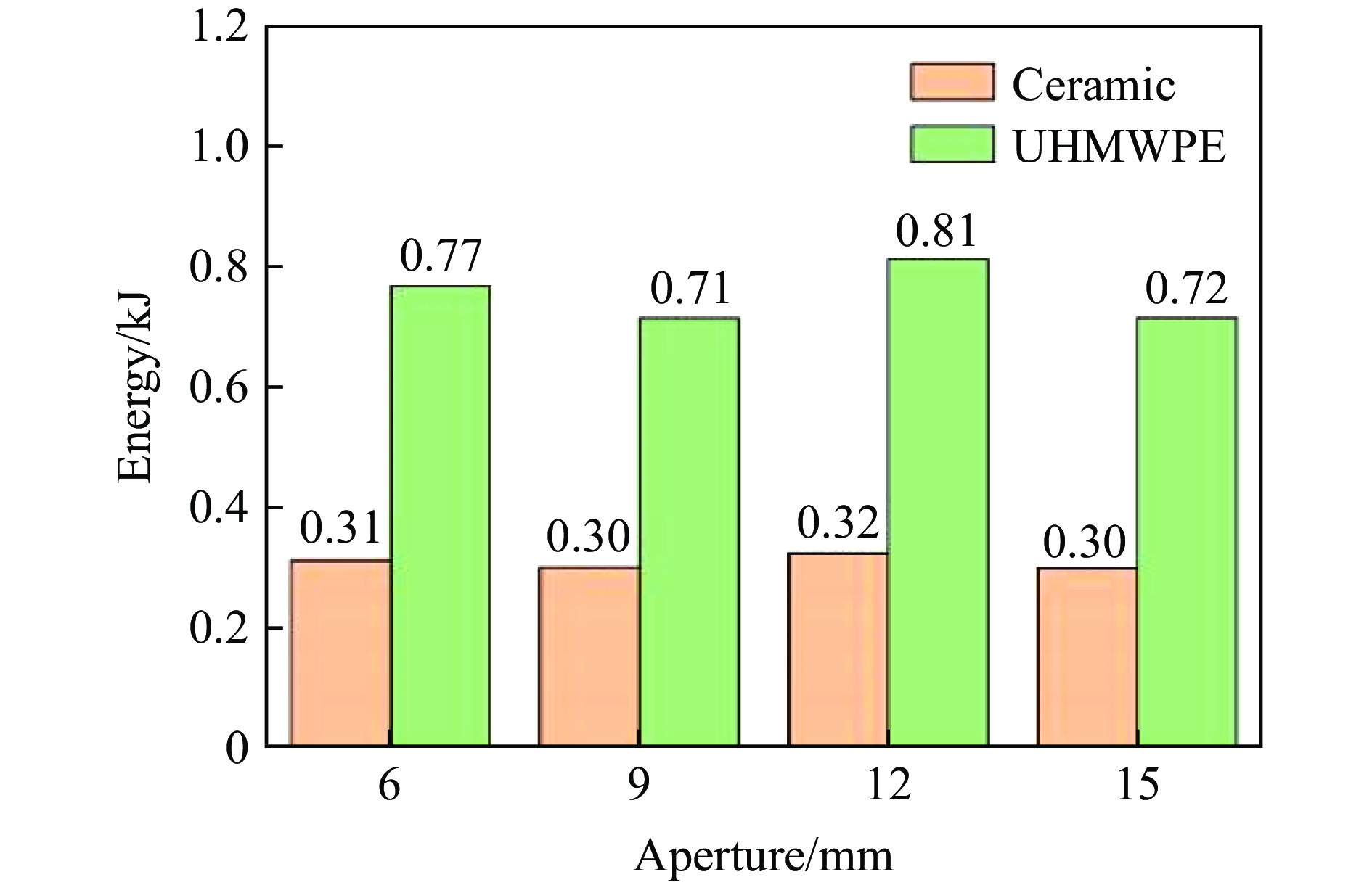
图 17 不同孔径TC4板的陶瓷层和UHMWPE层能量吸收对比
Figure 17. Comparison of energy absorption between ceramic and UHMWPE under TC4 plates with different apertures

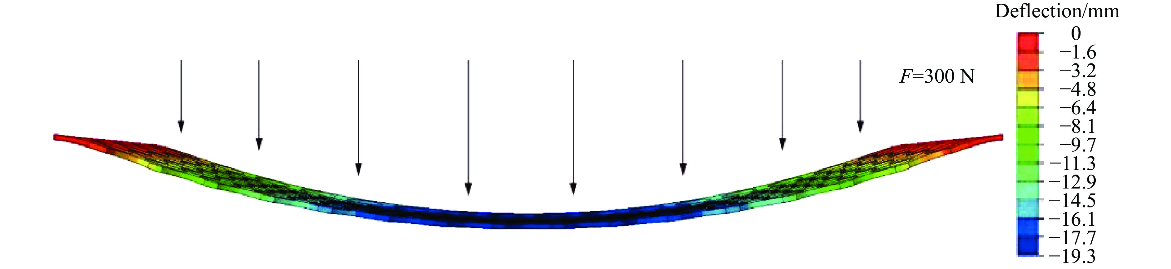
图 18 孔径9 mm的TC4板刚度测试变形
Figure 18. Deformation during stiffness testing of 9-mm-aperture TC4 board
表 1 试验条件
Table 1. Test conditions
试验 复合靶板配置厚度/mm 弹丸速度/(m·s−1) 面密度/(kg·m−2) B4C面板 TC4夹芯层 UHMWPE背板 1 9.0 2.0 10.0 501.4 37.7 2 9.0 2.0 10.0 475.2 3 10.0 1.0 10.0 507.5 37.5 4 10.0 1.0 10.0 468.9 5 10.0 1.5 10.0 487.0 38.8 6 10.0 1.5 10.0 486.4 7 10.0 10.0 487.2 34.8  下载: 导出CSV
${\rho _0}/({\text{g}} \cdot {\text{c}}{{\text{m}}^{{{ - 3}}}})$ G/GPa A B C/s−1 M N $\sigma _{\max }^{\text{f}}$ 2.51 197 0.927 0.7 0.005 0.85 0.67 0.2 HEL/GPa T/MPa β K1/GPa K2/GPa K3/GPa D1 D2 19 260 1 233 −593 2800 0.001 0.5
下载: 导出CSV
${\rho _0}/({\text{g}} \cdot {\text{c}}{{\text{m}}^{{{ - 3}}}})$ E1/GPa E2/GPa E3/GPa ${\nu _{12}}$ ${\nu _{13}}$ ${\nu _{13}}$ G12/GPa 0.97 30.7 30.7 1.97 0.008 0.044 0.044 1.97 G13/GPa G23/GPa Xt/GPa Xc/GPa S12/GPa S13/GPa S23/GPa 0.67 0.67 3.0 3.0 0.95 0.95 0.95
下载: 导出CSV
材料 ρ/(g·cm−3) G0/GPa A/MPa B/MPa n C m 弹芯(T12A) 7.80 82.0 1539 477 0.18 0.012 1.00 被甲(F11) 7.92 78.0 300 275 0.17 0.022 1.00 TC4 4.45 41.0 1100 845 0.58 0.014 0.753 材料 D1 D2 D3 D4 D5 弹芯(T12A) 0.15 0.72 1.66 0.43 0.00 被甲(F11) 0.50 0.00 0.00 0.00 0.00 TC4 0.09 0.27 0.48 0.014 3.8
下载: 导出CSV
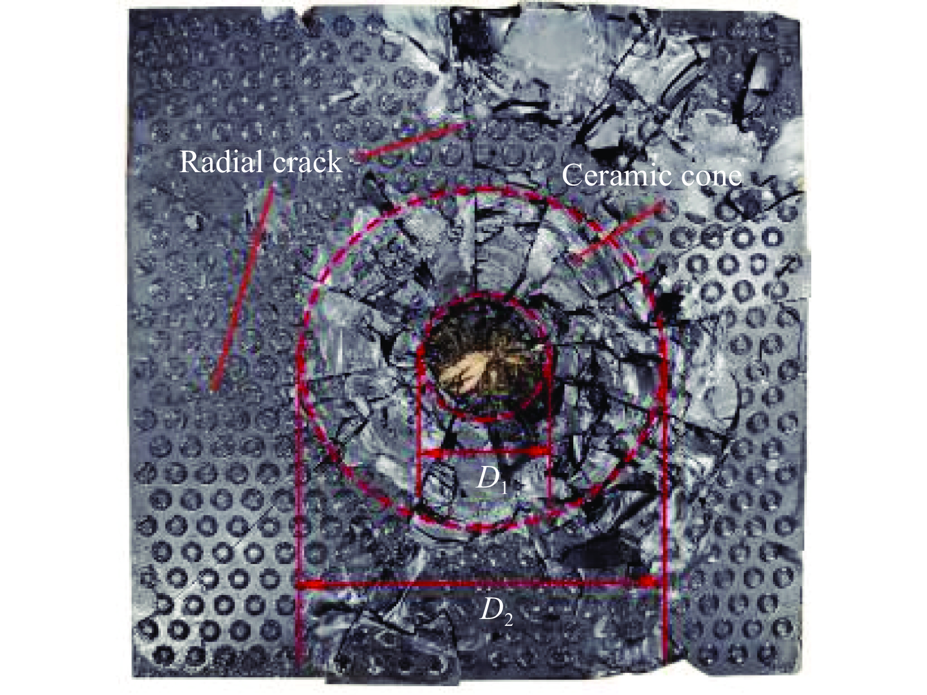
表 5 陶瓷锥顶部和底部直径测量值
Table 5. Measured values of the top and bottom diameters of ceramic cones
试验 试验靶板配置厚度/mm 弹丸速度/(m·s−1) 陶瓷锥顶部直径D1/mm 陶瓷锥底部直径D2/mm B4C TC4 1 9.0 2.0 501.4 34.61 108.97 2 9.0 2.0 475.2 29.34 100.08 3 10.0 1.0 507.5 44.86 130.59 4 10.0 1.0 468.9 30.06 102.85 5 10.0 1.5 487.0 32.42 117.58 6 10.0 1.5 486.4 30.36 115.32 7 10.0 487.2 30.20 100.95
下载: 导出CSV
-
[1] MEDVEDOVSKI E. Ballistic performance of armour ceramics: influence of design and structure: Part 2 [J]. Ceramics International, 2010, 36(7): 2117–2127. DOI: 10.1016/j.ceramint.2010.05.022. [2] LUO D J, WANG Y W, WANG F C, et al. The influence of metal cover plates on ballistic performance of silicon carbide subjected to large-scale tungsten projectile [J]. Materials and Design, 2020, 191: 108659. DOI: 10.1016/j.matdes.2020.108659. [3] NAGLIERI V, GLUDOVATZ B, TOMSIA A P, et al. Developing strength and toughness in bio-inspired silicon carbide hybrid materials containing a compliant phase [J]. Acta Materialia, 2015, 98: 141–151. DOI: 10.1016/j.actamat.2015.07.022. [4] LI J Z, ZHANG L S, HUANG F L. Experiments and simulations of tungsten alloy rods penetrating into alumina ceramic/603 armor steel composite targets [J]. International Journal of Impact Engineering, 2017, 101: 1–8. DOI: 10.1016/j.ijimpeng.2016.09.009. [5] 余毅磊, 蒋招绣, 王晓东, 等. 背板对氧化铝陶瓷薄板断裂锥形态的影响 [J]. 北京理工大学学报, 2021, 41(7): 713–720. DOI: 10.15918/j.tbit1001-0645.2020.107.YU Y L, JIANG Z X, WANG X D, et al. Effect of backing plate condition on fracture cone shape of alumina ceramic thin tiles [J]. Transactions of Beijing Institute of Technology, 2021, 41(7): 713–720. DOI: 10.15918/j.tbit1001-0645.2020.107. [6] ZAERA R, SÁNCHEZ-SÁEZ S, PÉREZ-CASTELLANOS J L, et al. Modelling of the adhesive layer in mixed ceramic/metal armours subjected to impact [J]. Composites Part A: Applied Science and Manufacturing, 2000, 31(8): 823–833. DOI: 10.1016/S1359-835X(00)00027-0. [7] NGUYEN L H, RYAN S, CIMPOERU S J, et al. The effect of target thickness on the ballistic performance of ultra high molecular weight polyethylene composite [J]. International Journal of Impact Engineering, 2015, 75: 174–183. DOI: 10.1016/j.ijimpeng.2014.07.008. [8] CAI S P, LIU J, ZHANG P, et al. Dynamic response of sandwich panels with multi-layered aluminum foam/UHMWPE laminate cores under air blast loading [J]. International Journal of Impact Engineering, 2020, 138: 103475. DOI: 10.1016/j.ijimpeng.2019.103475. [9] CAI S P, LIU J, ZHANG P, et al. Experimental study on failure mechanisms of sandwich panels with multi-layered aluminum foam/UHMWPE laminate core under combined blast and fragments loading [J]. Thin-Walled Structures, 2020, 159: 107227. DOI: 10.1016/j.tws.2020.107227. [10] SHEN Z W, HU D A, YANG G, et al. Ballistic reliability study on SiC/UHMWPE composite armor against armor-piercing bullet [J]. Composite Structures, 2019, 213: 209–219. DOI: 10.1016/j.compstruct.2019.01.078. [11] 武一丁, 王晓东, 余毅磊, 等. 纤维背板结构对B4C陶瓷复合装甲抗侵彻破碎特性的影响 [J]. 爆炸与冲击, 2023, 43(9): 091411. DOI: 10.11883/bzycj-2023-0133.WU Y D, WANG X D, YU Y L, et al. Affection of fiber backboard structure on the penetration and crushing resistance of B4C ceramic composite armor [J]. Explosion and Shock Waves, 2023, 43(9): 091411. DOI: 10.11883/bzycj-2023-0133. [12] DE OLIVEIRA BRAGA F, MILANEZI T L, MONTEIRO S N, et al. Ballistic comparison between epoxy-ramie and epoxy-aramid composites in Multilayered Armor Systems [J]. Journal of Materials Research and Technology, 2018, 7(4): 541–549. DOI: 10.1016/j.jmrt.2018.06.018. [13] DE OLIVEIRA BRAGA F, BOLZAN L T, RAMOS F J H T V, et al. Ballistic efficiency of multilayered armor systems with sisal fiber polyester composites [J]. Materials Research, 2018, 20(S2): 767–774. DOI: 10.1590/1980-5373-MR-2017-1002. [14] KARTIKEYA K, CHOUHAN H, RAM K, et al. Ballistic evaluation of steel/UHMWPE composite armor system against hardened steel core projectiles [J]. International Journal of Impact Engineering, 2022, 164: 104211. DOI: 10.1016/j.ijimpeng.2022.104211. [15] WU K K, CHEN Y L, YEH J N, et al. Ballistic impact performance of SiC ceramic-dyneema fiber composite materials [J]. Advances in Materials Science and Engineering, 2020, 2020: 9457489. DOI: 10.1155/2020/9457489. [16] NGUYEN L H, LÄSSIG T R, RYAN S, et al. A methodology for hydrocode analysis of ultra-high molecular weight polyethylene composite under ballistic impact [J]. Composites Part A: Applied Science and Manufacturing, 2016, 84: 224–235. DOI: 10.1016/j.compositesa.2016.01.014. [17] HAZZARD M K, TRASK R S, HEISSERER U, et al. Finite element modelling of Dyneema® composites: from quasi-static rates to ballistic impact [J]. Composites Part A: Applied Science and Manufacturing, 2018, 115: 31–45. DOI: 10.1016/j.compositesa.2018.09.005. [18] NUNES S G, SCAZZOSI R, MANES A, et al. Influence of projectile and thickness on the ballistic behavior of aramid composites: experimental and numerical study [J]. International Journal of Impact Engineering, 2019, 132: 103307. DOI: 10.1016/j.ijimpeng.2019.05.021. [19] JOHNSON G R, HOLMQUIST T J. An improved computational constitutive model for brittle materials [J]. AIP Conference Proceedings, 1994, 309(1): 981–984. DOI: 10.1063/1.46199. [20] MA Y Y, WANG J T, ZHAO G Z, et al. New insights into the damage assessment and energy dissipation weight mechanisms of ceramic/fiber laminated composites under ballistic impact [J]. Ceramics International, 2023, 43(13): 21966–21977. DOI: 10.1016/j.ceramint.2023.04.021. [21] HASHIN Z. Fatigue failure criteria for unidirectional fiber composites [J]. Journal of Applied Mechanics, 1981, 48(4): 846–852. DOI: 10.1115/1.3157744. [22] TAN L B, TSE K M, LEE H P, et al. Performance of an advanced combat helmet with different interior cushioning systems in ballistic impact: experiments and finite element simulations [J]. International Journal of Impact Engineering, 2012, 50: 99–112. DOI: 10.1016/j.ijimpeng.2012.06.003. [23] JOHNSON G R, COOK W H. Fracture characteristics of three metals subjected to various strains, strain rates, temperatures and pressures [J]. Engineering Fracture Mechanics, 1985, 21(1): 31–48. DOI: 10.1016/0013-7944(85)90052-9. [24] JIANG Y, QIAN K, ZHANG Y L, et al. Experimental characterisation and numerical simulation of ballistic penetration of columnar ceramic/fiber laminate composite armor [J]. Materials and Design, 2022, 224: 111394. DOI: 10.1016/j.matdes.2022.111394. [25] XIE Y, WANG T, WANG L M, et al. Numerical investigation of ballistic performance of SiC/TC4/UHMWPE composite armor against 7.62 mm AP projectile [J]. Ceramics International, 2022, 48(16): 24079–24090. DOI: 10.1016/j.ceramint.2022.05.088. [26] STRASSBURGER E, HUNZINGER M, PATEL P, et al. Analysis of the fragmentation of AlON and spinel under ballistic impact [J]. Journal of Applied Mechanics, 2013, 80(3): 031807. DOI: 10.1115/1.4023573. [27] GAO Y J, FENG X Y, LIU J X, et al. Design and ballistic penetration of “SiC/Ti6Al4V/UHMWPE” composite armor [J]. IOP Conference Series:Materials Science and Engineering, 2019, 563(4): 042043. DOI: 10.1088/1757-899X/563/4/042043. [28] PHOENIX S L, PORWAL P K. A new membrane model for the ballistic impact response and V50 performance of multi-ply fibrous systems [J]. International Journal of Solids and Structures, 2003, 40(24): 6723–6765. DOI: 10.1016/S0020-7683(03)00329-9. [29] GUO G D, ALAM S, PEEL L D. An investigation of the effect of a Kevlar-29 composite cover layer on the penetration behavior of a ceramic armor system against 7.62 mm APM2 projectiles [J]. International Journal of Impact Engineering, 2021, 157: 104000. DOI: 10.1016/j.ijimpeng.2021.104000. -


计量
- 文章访问数: 899
- HTML全文浏览量: 239
- PDF下载量: 260
- 被引次数: 0