


Cumulative damage effect and stability analysis of the rock slope with a locked segment under cyclic blasting
-
摘要: 岩石中存在许多微裂纹和微孔洞,这些微裂纹和微孔洞在动荷载作用下会萌生、扩展和聚并,导致岩石失稳和破坏。在进行爆破开挖时,预留岩体会受到循环爆破产生的动荷载影响,产生累积损伤,从而导致岩体强度降低,甚至破坏。为了模拟这一物理过程,将现有的能够较好地描述岩石动态损伤的岩石动态损伤本构模型通过二次开发嵌入到FLAC中,用于分析锁固型岩质边坡在循环爆破作用下的损伤效应及稳定性。结果表明:考虑岩质边坡累积损伤效应后,随着循环爆破次数的增加,边坡稳定性逐渐降低。对于锁固型岩质边坡,锁固段的破坏首先发生在两端,然后向中间扩散,岩体在其中呈现递进破坏模式。由于考虑了岩质边坡的累积损伤,每次爆破后边坡的安全系数都会减小。当不考虑累积损伤时,边坡的安全系数基本不变。另外,锁固段在软弱夹层中的位置影响边坡的破坏模式和稳定性。因此,在进行类似工程活动时,应考虑岩体的累积损伤效应,避免工程事故的发生。Abstract: There are many microcracks and micropores in the rock, which will initiate, propagate, and coalescence under dynamic loading, leading to rock instability and failure. When blasting excavation is carried out, the retained rock mass will be subjected to the dynamic loading generated by cyclic blasting, resulting in cumulative damage, which will lead to the reduction of the rock mass strength, and even failure. In order to simulate this physical process, the existing rock dynamic damage constitutive model, which could perfectly describe the rock dynamic damage induced by blasting, was embedded into FLAC through secondary development to analyze the cumulative damage of rock mass under cyclic blasting. And then it was adopted to simulate the damage effect and stability of the rock slope with the locked segment under cyclic blasting. The stability of the slope under cyclic blasting was determined by the displacement criterion method, and the safety factor of the slope after each blasting was obtained by the strength reduction method. Finally, the relationship between the failure mode and stability of the slope and the location of the locked segment was discussed by analyzing the damage, displacement field, and safety factor of the numerical models for different locations of the locked segment in the soft interlayer. The results show that the slope stability gradually decreases with increasing the number of cyclic blasting after considering the cumulative damage effect of the rock slope. For the rock slope with the locked segment, the damage of the locked segment firstly occurs at both ends, and then propagates to the middle, in which the rock mass shows a progressive failure mode. Because the cumulative damage of the rock slope is considered, the safety factor of the slope will decrease after each blasting. When the cumulative damage is not considered, the safety factor of the slope is basically unchanged. The failure mode of the rock slope with a locked segment under cyclic blasting is the combination of dynamic tensile failure and shear failure caused by rock mass slip. The location of the locked segment in the weak interlayer affects the failure mode and stability of the slope. Therefore, when carrying out similar engineering activities, the cumulative damage effect of rock mass should be considered to avoid engineering accidents.
-

图 5 每次爆破结束后锁固型边坡位移场及位移矢量场
Figure 5. Displacement field and displacement vector field of the slope after each blasting cycle

图 6 每次爆破结束后锁固型边坡的损伤分布
Figure 6. Damage distribution of the slope after each blasting cycle

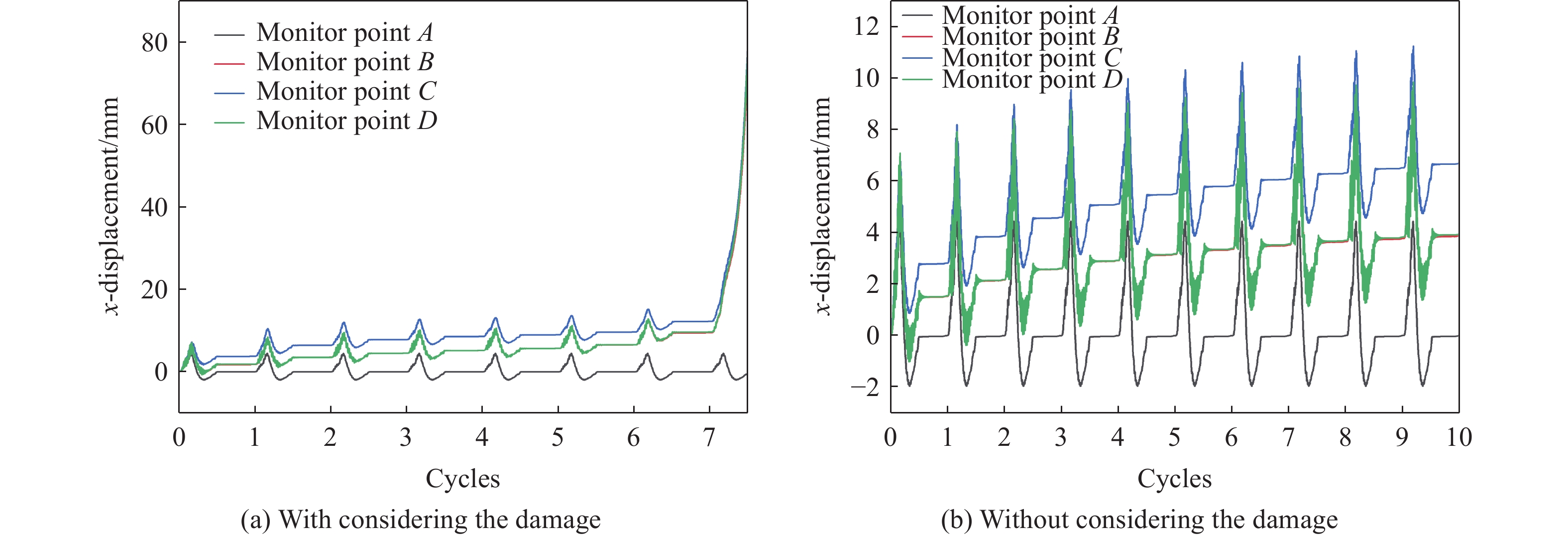
图 8 边坡在一次爆破作用下不同折减系数的位移
Figure 8. Displacements of monitor points with different strength-reduction ratios under the action of once blasting cycle

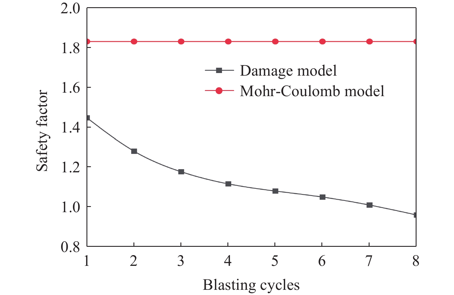
图 9 不同爆破次数下锁固型边坡的安全系数
Figure 9. Safety factor of the slope with the locked segment after each blasting

图 11 Model Ⅰ和Model Ⅲ边坡的累积损伤和位移云图
Figure 11. Cumulative damage and displacement distributions of Model Ⅰ and Model Ⅲ
密度/(kg·m−3) 弹性模量/GPa 泊松比 黏聚力/MPa 内摩擦角/(°) 抗拉强度/MPa 剪胀角/(°) α β 2700 68.69 0.228 27.7 55 5.6 12 3.15×10⁶ 2  下载: 导出CSV
表 2 模型物理力学参数
Table 2. Physical parameters for the models
岩体类型 密度/(kg·m−3) 弹性模量/GPa 泊松比 黏聚力/MPa 内摩擦角/(°) 抗拉强度/MPa 基岩 2700 20.0 0.24 5.00 42 3.00 风化岩体及锁固段 2500 0.8 0.25 0.20 34 0.20 软弱夹层 2200 0.6 0.25 0.04 18 0.02
下载: 导出CSV
-
[1] 黄润秋. 汶川8.0级地震触发崩滑灾害机制及其地质力学模式 [J]. 岩石力学与工程学报, 2009, 28(6): 1239–1249. DOI: 10.3321/j.issn:1000-6915.2009.06.021.HUANG R Q. Mechanism and geomechanical modes of landslide hazards triggered by Wenchuan 8.0 earthquake [J]. Chinese Journal of Rock Mechanics and Engineering, 2009, 28(6): 1239–1249. DOI: 10.3321/j.issn:1000-6915.2009.06.021. [2] ROBACK K, CLARK M K, WEST A J, et al. The size, distribution, and mobility of landslides caused by the 2015 M(w)7.8 Gorkha earthquake, Nepal [J]. Geomorphology, 2018, 301: 121–138. DOI: 10.1016/j.geomorph.2017.01.030. [3] WANG M, MA G T, WANG F. Numerically investigation on blast-induced wave propagation in catastrophic large-scale bedding rockslide [J]. Landslides, 2021, 18: 785–797. DOI: 10.1007/s10346-020-01537-w. [4] CUI F P, LI B, XIONG C, et al. Dynamic triggering mechanism of the Pusa mining-induced landslide in Nayong County, Guizhou Province, China [J]. Geomatics, Natural Hazards & Risk, 2022, 13(1): 123–147. DOI: 10.1080/19475705.2021.2017020. [5] XUE L, QIN S Q, PAN X H, et al. A possible explanation of the stair-step brittle deformation evolutionary pattern of a rockslide [J]. Geomatics, Natural Hazards & Risk, 2017, 8(2): 1456–1476. DOI: 10.1080/19475705.2017.1345793. [6] HUANG R Q. Mechanisms of large-scale landslides in China [J]. Bulletin of Engineering Geology and the Environment, 2012, 71(1): 161–170. DOI: 10.1007/s10064-011-0403-6. [7] CHEN H R, QIN S Q, XUE L, et al. Why the Xintan landslide was not triggered by the heaviest historical rainfall: mechanism and review [J]. Engineering Geology, 2021, 294: 106379. DOI: 10.1016/j.enggeo.2021.106379. [8] LI S Y, LI D D, LIU H D, et al. Formation and failure mechanism of the landslide: a case study for Huaipa, western Henan, China [J]. Environmental Earth Sciences, 2021, 80(15): 478. DOI: 10.1007/s12665-021-09781-6. [9] TANG H M, ZOU Z X, XIONG C R, et al. An evolution model of large consequent bedding rockslides, with particular reference to the Jiweishan rockslide in southwest China [J]. Engineering Geology, 2015, 186: 17–27. DOI: 10.1016/j.enggeo.2014.08.021. [10] DONG J Y, WANG C, HUANG Z Q, et al. Dynamic response characteristics and instability criteria of a slope with a middle locked segment [J]. Soil Dynamics and Earthquake Engineering, 2021, 150: 106899. DOI: 10.1016/j.soildyn.2021.106899. [11] DAI Z Y, ZHANG L, WANG Y L, et al. Deformation and failure response characteristics and stability analysis of bedding rock slope after underground adverse slope mining [J]. Bulletin of Engineering Geology and the Environment, 2021, 80(6): 4405–4422. DOI: 10.1007/s10064-021-02258-7. [12] WANG W C, YAN Y F, QU Y, et al. Shallow failure of weak slopes in Bayan Obo West Mine [J]. International Journal of Environmental Research and Public Health, 2022, 19(5): 9755. DOI: 10.3390/ijerph19159755. [13] WU Z J, JI X K, LIU Q S, et al. Study of microstructure effect on the nonlinear mechanical behavior and failure process of rock using an image-based-FDEM model [J]. Computers and Geotechnics, 2020, 121: 103480. DOI: 10.1016/j.compgeo.2020.103480. [14] KACHANOV L. Time of rupture process under creep conditions [J]. Izvestiia Akademii Nauk SSSR, Otdelenie Teckhnicheskikh Nauk, 1958, 8: 26–31. [15] LEMAITRE J. How to use damage mechanics [J]. Nuclear Engineering and Desig, 1984, 80(2): 233–245. DOI: 10.1016/0029-5493(84)90169-9. [16] ZHANG Q B, ZHAO J. A review of dynamic experimental techniques and mechanical behaviour of rock materials [J]. Rock Mechanics and Rock Engineering, 2014, 47: 1411–1478. DOI: 10.1007/s00603-013-0463-y. [17] GRADY D E, KIPP M E. Continuum modelling of explosive fracture in oil shale [J]. International Journal of Rock Mechanics and Mining Sciences & Geomechanics Abstracts, 1980, 17(3): 147–157. DOI: 10.1016/0148-9062(80)91361-3. [18] TAYLOR L M, CHEN E P, KUSZMAUL J S. Microcrack-induced damage accumulation in brittle rock under dynamic loading [J]. Computer Methods in Applied Mechanics and Engineering, 1986, 55(3): 301–320. DOI: 10.1016/0045-7825(86)90057-5. [19] YANG R, BAWDEN W F, KATSABANIS P D. A new constitutive model for blast damage [J]. International Journal of Rock Mechanics and Mining Sciences & Geomechanics Abstracts, 1996, 33(3): 245–254. DOI: 10.1016/0148-9062(95)00064-X. [20] LIU L Q, KATSABANIS P D. Development of a continuum damage model for blasting analysis [J]. International Journal of Rock Mechanics and Mining Sciences, 1997, 34(2): 217–231. DOI: 10.1016/S0148-9062(96)00041-1. [21] ZHOU X P. Analysis of the localization of deformation and the complete stress-strain relation for mesoscopic heterogeneous brittle rock under dynamic uniaxial tensile loading [J]. International Journal of Solids and Structures, 2004, 41(5/6): 1725–1738. DOI: 10.1016/j.ijsolstr.2003.07.007. [22] 刘红岩, 李俊峰, 裴小龙. 单轴压缩下断续节理岩体动态损伤本构模型 [J]. 爆炸与冲击, 2018, 38(2): 316–323. DOI: 10.11883/bzycj-2016-0261.LIU H Y, LI J F, PEI X L. A dynamic damage constitutive model for rockmass with intermittent joints under uniaxial compression [J]. Explosion and Shock Waves, 2018, 38(2): 316–323. DOI: 10.11883/bzycj-2016-0261. [23] SONG J, KIM K. Micromechanical modeling of the dynamic fracture process during rock blasting [J]. International Journal of Rock Mechanics and Mining Sciences & Geomechanics Abstracts, 1996, 33(4): 387–391, 393–394. DOI: 10.1016/0148-9062(95)00072-0. [24] AMICHAI M, DAVIDE E. Modelling of blast-induced damage in tunnels using a hybrid finite-discrete numerical approach [J]. Journal of Rock Mechanics and Geotechnical Engineering, 2014, 6(6): 565–573. DOI: 10.1016/j.jrmge.2014.09.002. [25] HU Y G, LU W B, CHEN M, et al. Numerical simulation of the complete rock blasting response by SPH-DAM-FEM approach [J]. Simulation Modelling Practice and Theory, 2015, 56: 55–68. DOI: 10.1016/j.simpat.2015.04.001. [26] 胡英国, 卢文波, 陈明, 等. 岩体爆破近区临界损伤质点峰值震动速度的确定 [J]. 爆炸与冲击, 2015, 35(4): 547–554. DOI: 10.11883/1001-1455(2015)04-0547-08.HU Y G, LU W B, CHEN M, et al. Determination of critical damage PPV near the blast hole of rock-mass [J]. Explosion and Shock Waves, 2015, 35(4): 547–554. DOI: 10.11883/1001-1455(2015)04-0547-08. [27] 王磊, 朱哲明, 周磊, 等. 冲击载荷作用下圆孔缺陷对裂纹动态扩展行为的影响规律 [J]. 爆炸与冲击, 2021, 41(8): 083105. DOI: 10.11883/bzycj-2021-0062.WANG L, ZHU Z M, ZHOU L, et al. Influence of circular hole defect on dynamic crack propagation behavior under impact loads [J]. Explosion and Shock Waves, 2021, 41(8): 083105. DOI: 10.11883/bzycj-2021-0062. [28] 周磊, 姜亚成, 朱哲明, 等. 动载荷作用下裂隙岩体的止裂机理分析 [J]. 爆炸与冲击, 2021, 41(5): 053102. DOI: 10.11883/bzycj-2020-0125.ZHOU L, JIANG Y C, ZHU Z M, et al. Mechanism study of preventing crack propagation of fractured rock under dynamic loads [J]. Explosion and Shock Waves, 2021, 41(5): 053102. DOI: 10.11883/bzycj-2020-0125. [29] VERMA H K, SAMADHIYA N K, SINGH M, et al. Blast induced rock mass damage around tunnels [J]. Tunnelling and Underground Space Technology, 2018, 71: 149–158. DOI: 10.1016/j.tust.2017.08.019. [30] ZAREIFARD M R. A new semi-numerical method for elastoplastic analysis of a circular tunnel excavated in a Hoek-Brown strain-softening rock mass considering the blast-induced damaged zone [J]. Computers and Geotechnics, 2020, 122: 103476. DOI: 10.1016/j.compgeo.2020.103476. [31] JIANG N, ZHOU C B, LU S W, et al. Propagation and prediction of blasting vibration on slope in an open pit during underground mining [J]. Tunnelling and Underground Space Technology, 2017, 70: 409–421. DOI: 10.1016/j.tust.2017.09.005. [32] CAO F, ZHANG S, LING T H. Analysis of cumulative damage for shared rock in a neighborhood tunnel under cyclic blasting loading using the ultrasonic test [J]. Shock and Vibration, 2020(1): 8810089. DOI: 10.1155/2020/8810089. [33] TU W F, LI L P, ZHOU Z Q, et al. Thickness calculation of accumulative damaged zone by rock mass blasting based on Hoek-Brown failure criterion [J]. International Journal of Geomechanics, 2022, 22(2): 04021273. DOI: 10.1061/(ASCE)GM.1943-5622.0002257. [34] HE M C, FENG J L, SUN X M. Stability evaluation and optimal excavated design of rock slope at Antaibao open pit coal mine, China [J]. International Journal of Rock Mechanics and Mining Sciences, 2008, 45(3): 289–302. DOI: 10.1016/j.ijrmms.2007.05.007. [35] QI X, ZHANG Y P. Stability analysis of soil-rock mixed slope under earthquake environment [J]. Fresenius Environmental Bulletin, 2021, 30(4A): 4384–4390. [36] FAHIMIFAR A, KARAMI M, FAHIMIFAR A. Modifications to an elasto-visco-plastic constitutive model for prediction of creep deformation of rock samples [J]. Soils and Foundations, 2015, 55(6): 1364–1371. DOI: 10.1016/j.sandf.2015.10.003. [37] KABWE E, KARAKUS M, CHANDA E K. Creep constitutive model considering the overstress theory with an associative viscoplastic flow rule [J]. Computers and Geotechnics, 2020, 124: 103629. DOI: 10.1016/j.compgeo.2020.103629. [38] SUN B J, LIU Q W, LI W T, et al. Numerical implementation of rock bolts with yield and fracture behaviour under tensile-shear load [J]. Engineering Failure Analysis, 2022, 139: 106462. DOI: 10.1016/j.engfailanal.2022.106462. [39] 左双英, 肖明, 续建科, 等. 隧道爆破开挖围岩动态损伤效应数值模拟 [J]. 岩土力学, 2011, 32(10): 3171–3176, 3184. DOI: 10.16285/j.rsm.2011.10.040.ZUO S Y, XIAO M, XU J K, et al. Numerical simulation of dynamic damage effect of surrounding rocks for tunnels by blasting excavation [J]. Rock and Soil Mechanics, 2011, 32(10): 3171–3176, 3184. DOI: 10.16285/j.rsm.2011.10.040. [40] 夏祥, 李海波, 李俊如, 等. 岭澳核电站二期工程基岩爆破安全阈值分析 [J]. 岩土力学, 2008, 29(11): 2945–2951, 2956. DOI: 10.16285/j.rsm.2008.11.022.XIA X, LI H B, LI J R, et al. Research on vibration safety threshold for rock under blasting excavation [J]. Rock and Soil Mechanics, 2008, 29(11): 2945–2951, 2956. DOI: 10.16285/j.rsm.2008.11.022. [41] 费鸿禄, 苑俊华. 基于爆破累积损伤的边坡稳定性变化研究 [J]. 岩石力学与工程学报, 2016, 35(S2): 3868–3877. DOI: 10.13722/j.cnki.jrme.2015.1192.FEI H L, YUAN J H. Study of slope stability based on blasting cumulative damage [J]. Chinese Journal of Rock Mechanics and Engineering, 2016, 35(S2): 3868–3877. DOI: 10.13722/j.cnki.jrme.2015.1192. [42] DENG Z Y, LIU X R, LIU Y Q, et al. Model test and numerical simulation on the dynamic stability of the bedding rock slope under frequent microseisms [J]. Earthquake Engineering and Engineering Vibration, 2020, 19(4): 919–935. DOI: 10.1007/s11803-020-0604-8. [43] BAO M, CHEN Z H, ZHANG L F, et al. Experimental study on the sliding instability mechanism of slopes with weak layers under creeping action [J]. Measurement, 2023, 212: 112690. DOI: 10.1016/j.measurement.2023.112690. -


计量
- 文章访问数: 451
- HTML全文浏览量: 108
- PDF下载量: 154
- 被引次数: 0