


Application of high-speed 3D-DIC measurement technology in perforation test of armor steel
-
摘要: 数字图像相关(digital image correlation, DIC)技术作为一种非接触、非干涉的全场无损光学量测技术,可获取材料表面的动态变形信息和破坏过程。为了评估装甲钢的抗弹性能并探索高速三维数字图像相关(3D-DIC)技术在钢板贯穿试验测试中的应用,基于氢氧爆轰驱动弹道枪开展了7发15 mm口径可变形弹体以不同速度(255~568 m/s)冲击不同厚度(5、8和10 mm)高强高硬装甲钢板的试验,并结合帧率为144 000 s−1的高速3D-DIC测试技术获取了靶板的离面位移和应变时程。随后,基于前期标定并验证的装甲钢本构模型参数,对上述试验进行了数值模拟。通过对比弹体残余速度和长度验证了有限元分析方法的可靠性。进一步通过对比试验与数值模拟得到的靶背离面位移时程曲线和不同时刻靶背的应变云图,验证了高速3D-DIC测试结果的准确性。最后,对比分析了靶板最大离面位移与弹体冲击速度和装甲钢板厚度的关系。高速3D-DIC测试技术的应用可为相关试验测试提供参考,靶板最大离面位移分析结果可为屏障类防护结构的分析验证和优化设计提供试验依据。Abstract: As a non-contact, non-interference full-field non-destructive optical measurement technology, digital image correlation (DIC) technology can obtain the dynamic deformation information on the surface of materials and failure process. Aiming to evaluate the ballistic performance of armor steel and explore the application of high-speed three-dimensional digital image correlation (3D-DIC) technology in perforation test of armor steel plates, impact tests by seven shots on high strength and hardness armor steel plates with different thicknesses were conducted, in which 15-mm-caliber deformable projectile at various velocities were fired by using hydrogen-oxygen detonation ballistic gun, whilst the high-speed 3D-DIC measurement technology with frame rate of 144000 s−1 was adopted to extract the out-of-plane displacement and strain field-time histories of the target. Then, based on the calibrated and validated constitutive model parameters of armor steel obtained in previous work, the current impact test is numerically simulated and the corresponding finite element model is validated by comparing with the simulated residual projectile velocities and lengths with test data. Furthermore, by comparing the out-of-plane displacement-time histories and strain contours at the rear of target obtained by numerical simulation and test, the accuracy of results obtained by high-speed 3D-DIC is validated. Finally, the relationship between maximum out-of-plane displacement with projectile impact velocity and armor steel plate thickness is analyzed. The results show that the relatively smaller out-of-plane displacements were obtained due to the shear plugging failure for 8 mm-thick targets. Under the identical impact energy, the unperforated targets with the thickness of 10 mm absorb the most of energy and exhibit larger out-of-plane displacements compared with those in targets with the thicknesses of 5 mm and 8 mm. The application of high-speed 3D-DIC technology in this study can provide a reference for related tests, and the analysis result of maximum out-of-plane displacement of target can be used as the experimental basis for the analysis, verification and optimal design in protective barrier structures.
-
Key words:
- high-speed 3D-DIC /
- armor steel /
- perforation test /
- residual velocity /
- out-of-plane displacement
-
在下穿各种构筑物的市政地下工程中,钻爆法由于成本低、专用设备少、不影响地面交通等特点被广泛采用[1-2]。爆破施工对地表既有建(构)筑物产生的振动影响,受到普遍重视,将振速作为控制爆破的重要指标。目前,能够有效控制振速大小的抗减震措施主要有掏槽(位置与结构形式)设置、微差爆破、预裂爆破及水压爆破等,其中微差是一种可控的“主观条件”,对爆破过程中振速的影响至关重要[3-4]。然而,由于隧道爆破开挖过程中炸药性能、装药结构、地质情况等因素影响, 对微差爆破在介质内部产生的物理力学现象还没有准确的认识和严密的理论。确定微差时间间隔常用新自由面假说、残余应力假说、最小抵抗线假说等,其依据均存在局限性[5-7]。考虑降震效果选取合理微差时间间隔,用以下两种观点可以解释:(1)不同微差时间起爆的炮孔产生的地震波相互干扰以降低振动影响;(2)不同微差时间起爆的炮孔产生的地震波主震相错开,从而达到理想减震效果。前者由于各段炮孔位置不同,即使对相同测点,各段地震波也存在不同的传播距离和时间,加上地质条件影响,相邻段位地震波相互干扰情况复杂,若盲目采用此观点选取合理微差间隔,可能导致振速出现随机增大;采用相邻炮孔产生的振速波形主震相在时间轴上无相互影响的方式,进行微差爆破降震较理想[8]。
在复杂地质条件下,微差产生的地震波主震相及波形变化规律、不同微差时间间隔的降震效果等均会对合理微差时间取值范围产生重大影响。但目前尚未见对上述问题的深入探讨。基于此,本文中,以在建的莞惠城际穿越复合地层段作为工程背景,结合现场测试数据,采用理论与数值分析相结合的手段,开展城市隧道穿越复合地层中合理微差时间间隔的研究,拟为类似工程爆破设计和施工提供参考。
1. 工程概况
莞惠城际轨道交通项目线路全长约97 km,区间结构形式复杂,隧道总长超过80%,以中隔墙法微差爆破施工为主。覆土表层为第四系冲洪积的软塑至硬塑状黏性土,其下为稍密至中密的饱和砂类土,下伏基岩为强至弱风化混合片麻岩,岩体较破碎,节理裂隙发育。洞身上部主要穿越透水性强、无自稳能力、易坍塌的富水饱和砂土地层,下部多为整体性较差的全风化混合片麻岩,隧道区间围岩总体呈现出复杂、特殊的“上软下硬”复合地层特征。
围岩分布包含Ⅲ~Ⅵ级,隧道最小埋深不足9 m,多数区间属于浅埋,施工将不可避免的对上部既有构筑物产生影响。地表交通繁忙,建筑物耸立,隧道下穿地段房屋基础多为天然基础及人工挖孔桩基础,房屋多为中~低层框架结构及砖混结构,且部分房屋修建年代久远,已出现开裂、倾斜等病害,尽管采取了注浆加固措施,但爆破施工时仍需降低对地表的振动影响,严格控制房屋沉降,避免既有病害继续扩展或造成新的破坏。
2. 岩体弹性波传播规律
岩体中传播的波分为体波和面波两类,面波在传播方向上衰减比体波慢,传播距离更大,在岩体表面(地表、节理裂隙等)波形中占主导地位,主震相往往由面波产生[9]。在莞惠城际项目中设计合理微差间隔时,主要考虑:(1)相邻炮孔爆破产生的主震相不叠加,此时得到微差最小时间间隔,为τmin;(2)对于振动控制,最理想情况是相邻爆破间完全无振速叠加,但由于所需微差时间间隔长,导致各炮间不存在相互作用,与微差爆破理念不符,由此得到微差最大时间间隔,为τmax;(3)相邻炮孔爆破后,后爆孔产生的初震相不与先爆孔产生的主震相叠加,此时微差时间间隔较合理,为τ。由此可知,微差合理时间间隔的研究涉及的主要参数有爆心距(监测点到爆源的距离R)和弹性波波速(纵波波速vP、横波波速vS、面波波速vR)。
根据莞惠城际区间复合地层条件,结合实际隧道围岩分级情况,利用岩石超声波参数测定仪及纵横波换能器测定,各级围岩波速判定见表 1。
表 1 不同围岩等级的波速Table 1. Wave velocities of different levels surrounding rock围岩等级 vP/(km·s-1) vS/(km·s-1) vR/(km·s-1) Ⅲ 2.5 1.47 1.35 Ⅳ 2.0 1.18 1.08 Ⅴ 1.5 0.88 0.81 Ⅵ 1.0 0.59 0.54 3. 合理微差时间间隔研究
3.1 不同围岩段现场测试结果
为探明在不同围岩等级的复合地层中进行微差爆破时弹性波的特点及传播规律,并确定合理微差间隔,选取莞惠城际典型Ⅲ级和Ⅵ级围岩段微差爆破监测结果进行分析。依据爆破设计参数,雷管段位1、3、5、7、9的名义延时分别为0、50、110、200、310 ms。典型Ⅲ级围岩段(见图 1(a))隧道埋深40 m,主频62~111.1 Hz,最大段药量均为12.0 kg;典型Ⅵ级围岩段(见图 1(b))隧道埋深18 m,主频65.0~81.6 Hz,最大段药量为7.2 kg。
各监测点微差爆破前300 ms的振动波形, 如图 2所示。限于篇幅,仅列出测点A、B、E、F的波形,R表示爆心距。由图 2可见:(1)在围岩等级和微差爆破间隔时间相同时,随着测点爆心距增加,振动波形更易叠加,且爆心距增加幅度越大,波形主震相持续时间越长。(2)测点F出现了较明显波形叠加效应,而测点A各段位波形基本分离,结合前述爆心距的影响,当围岩条件变差时,振动波形更易出现叠加。(3)Ⅲ级围岩测点爆心距R=45~60 m,波形持续时间tw≈100 ms(7区基本能够反应一个完整的波形振动过程),主震相持续时间ts=30~50 ms;Ⅵ级围岩测点爆心距R=25~33 m,波形持续时间tw≥100 ms,主震相持续时间ts=25~40 ms。
由莞惠城际围岩波速和微差取值方案,不同围岩等级中弹性波的波形属性如表 2,微差时间间隔取值如表 3,其结果均符合波的传播及衰减规律。表中,τmin=ts,τ=ts+tR-tP,τmax=tw。参照微差爆破施工过程中振速不出现明显叠加(主震相在时间轴上分离)的原则,表 3中的适宜时间差τ=50 ms,即初步判定微差设计方案(雷管段位设计)较合理,能够使爆心距R≈25 m的监测点(据现场测试最大振速出现在此爆心距范围内)的主震相不出现明显的叠加效应。
表 2 弹性波在不同围岩等级传播属性Table 2. Transport properties of elastic waves of different levels of surrounding rock围岩等级 R/m vP/(km·s-1) vS/(km·s-1) vR/(km·s-1) tP/ms tS/ms tR/ms (tR-tP)/ms ts/ms tw/ms Ⅲ 45 2.5 1.47 1.35 18 30.6 33.3 15.3 30 ≈100 Ⅲ 60 2.5 1.47 1.35 24 40.8 44.4 20.0 50 ≈100 Ⅵ 25 1.0 0.59 0.54 25 42.4 46.3 21.3 25 ≈100 Ⅵ 33 1.0 0.59 0.54 35 59.3 64.8 29.8 40 >100 表 3 微差时间间隔取值Table 3. Values of microsecond time interval围岩等级 R/m τmin/ms τ/ms τmax/ms Ⅲ 45 30 45.3 ≈100 Ⅲ 60 50 70.0 ≈100 Ⅵ 25 25 46.3 ≈100 Ⅵ 33 40 69.8 >100 3.2 计算模型
为验证现场分析所得微差时间间隔的合理性,研究穿越复合地层条件下的微差降震效果,选择工程中振速重点控制的Ⅵ级围岩段进行模拟分析,该区域地表房屋密集、埋深较浅、开挖影响大。为了详细描述不同微差时间间隔下爆破的叠加效应,选取掌子面上方地表侧向20 m范围为重点研究对象[10],并考虑振速最大值的位置(位于已开挖区距掌子面5~10 m处地表,爆心距约24 m)布置控制点(见图 3(a))。模型(见图 3(b))中,通过设置无反射条件(除地表为自由面外),避免边界处波的反射对求解域的影响,并以此模拟无限大空间。模拟掏槽爆破及相邻段位掘进孔爆破,即实际爆破涉及的段位1、3,设置两次微差时间间隔差为0、2、5、8、10、15、20、30、40、50、70、100、150、200 ms,共14种工况。计算参数参考莞惠城际地勘资料、现场材料实验、规范,并结合岩体的动力学性质进行选取,见表 4。表中,E为动弹性模量,ν为泊松比,ρ为密度。
表 4 模型力学参数Table 4. Mechanical parameters of the model岩体类型 岩体名称 E/GPa ν ρ/(t·m-3) 软岩层 黏土类地层 0.3 0.35 1.950 软岩层 饱和砂土 0.5 0.33 2.095 硬岩层 全风化混合片麻岩 0.7 0.33 2.300 硬岩层 弱风化混合片麻岩 1.5 0.31 2.350 计算中,采用Lagrange法模拟炸药与岩体共用节点,通过JWL状态方程描述炸药[11];不同段位药量按现场实际取值;考虑围岩失效情况,本构模型采用塑性动力学模型;为实现炸药作用时间及计算完整性,单孔爆破作用时间(三角荷载)为112 ms[12];模拟时对应耦合装药结构,但实际爆破设计为不耦合装药[13]。因此,依据两种装药结构在炮孔壁上产生的荷载值相等的原则,对炸药爆速进行折减,计算可知爆速为1 200 m/s。
3.3 结果分析
根据现场对测点F的持续监测,该测点位于左线隧道开挖面后5 m左右时(对应图 3中测点1)出现最大振速,为14.6 mm/s,如图 4所示。
提取测点1在不同典型微差时间间隔下的垂向振速波形图,如图 5所示。
 图 5 不同微差间隔下测点1的振速波形Figure 5. Velocity waveforms of measuring point 1 of different microsecond time interval
对比图 4与图 5(c)可知,现场实测与数值模拟获取的波形规律相似,最大振速、波峰波谷个数等均具有较好的耦合性。由图 5可知:随着微差时间间隔增加,第1、2炮产生的主震相逐渐分离,波形叠加效应减弱;超过20 ms时,主震相已基本分离,此后时间对最大振速不会产生较大影响;20m s时,第2炮产生的最大振速明显过大,表明主震相虽已分离,但与第1炮产生的余震相仍存在叠加;100 ms时,波形已不存在明显叠加,两炮之间基本独立。
选取不发生振动波形叠加时(微差时间间隔200 ms)的计算结果进行分析,各测点垂向振速波形见图 6,图中,ts1为主震相时间,ts2为余震相时间。第1、2炮各测点最大垂向振速见表 5。
表 5 各测点垂向最大振速(τ=200 ms)Table 5. Maximum vibration velocitiesof measuring points测点 vy/(mm·s-1) 第1炮 第2炮 1 14.3 10.0 2 11.2 8.5 3 10.6 7.6 4 7.3 5.8 5 3.4 2.4 6 2.2 1.9 由图 6和表 5可知:在相同测点,第1炮产生的振速量值明显大于第2炮,即掏槽孔爆破对各质点振速影响最大,且各测点波形均未出现叠加,各炮产生的振动波形独立;穿越复合地层时,爆心距增大将导致主震相、余震相及波的持续时间增加,波形更易发生叠加,与现场实测波形分析结果相同;测点1和3爆心距相同,但其振速波形和量值均不同,已开挖土体上方的测点受空洞效应影响显著,振速明显大于测点3,量值分别为14.3和10.6 mm/s。
由图 7可知,在复合地层中采用微差爆破效果明显好于普通爆破。当微差时间选择不当时,地表振速将超过工程安全控制标准15 mm/s;合理间隔能使振速降低,但各测点适宜的微差时间间隔不同,如测点5在40 ms时振速变大,而测点6则降低;质点爆心距变大时(测点5和6),需更长微差时间间隔才能使振速“稳定”,主要原因是爆心距增大导致主震相持续时间变长,各炮之间更易叠加。
 图 7 微差时间间隔与质点振动峰值速度关系曲线Figure 7. Curves of relation between microsecond time intervaland peak particle velocity
上述分析表明,每个测点均存在最适宜的爆破微差时间间隔。但实际工程中,在不同爆心距、地质条件、炮孔布置等因素影响下,相邻炮孔产生的振动波形不同,此时,理论的最适宜微差时间间隔无法应用。因此,针对隧道爆破开挖认为合理微差时间间隔的确定,以振速控制区内各炮振速稳定且波形不出现叠加效应为原则。为更好地描述微差时间间隔和降震之间的联系,引入“降震率”概念[14]:
δ=v0−vv (6) 式中:v0为齐发(微差时间间隔为零)爆破振动速度峰值;v为不同微差时间间隔的速度峰值。
由图 8可知:降震率在微差时间间隔0~35 ms间变化明显,但整体上小于稳定降震率;在振速较大且控制要求严格的测点1~4,50 ms时降震基本保持不变,超过70 ms时,各测点降震率均保持不变。因此,在本复合地层区间,微差时间间隔取50~70 ms较适宜,与现场测试结论基本吻合。
 图 8 微差时间间隔与降震率关系曲线Figure 8. Curves of relation between microsecond time intervaland reducing-vibration rate
4. 结论
(1) 现场实测振动波形分析及数值模拟结论均表明,在莞惠城际项目“上软下硬”复合地层中微差爆破效果较好,第1、2炮适宜的微差时间间隔为50~70 ms。
(2) 围岩条件相同,振动波形和主震相的持续时间均随着爆心距的增加而变长;而围岩条件变差时,振动波形更易出现波形叠加现象。
(3) 随着微差时间间隔增加,第1、2炮产生的主震相逐渐分离,20 ms时波形仍与前炮余震相存在叠加,100 ms时波形已基本独立。降震率在0~35 ms间变化明显,且整体上小于稳定降震率,70 ms后各测点降震率均保持不变。
(4) 在复合地层中,两侧点爆心距相同时,已开挖土体上方的测点受空洞效应影响显著,其振速明显偏大。
-
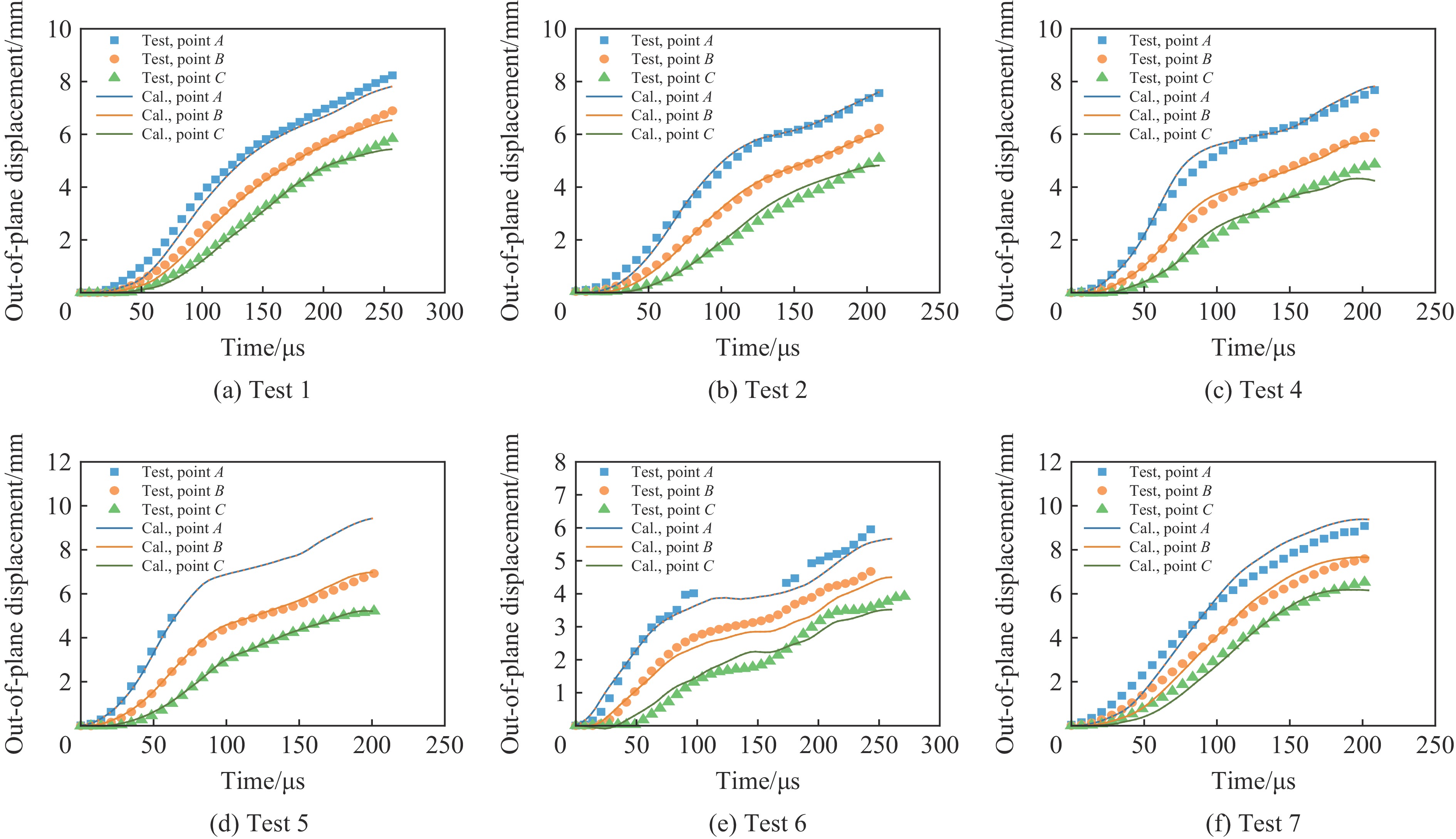
图 12 靶板离面位移时程对比
Figure 12. Comparisons of out-of-plane displacement-time histories of targets
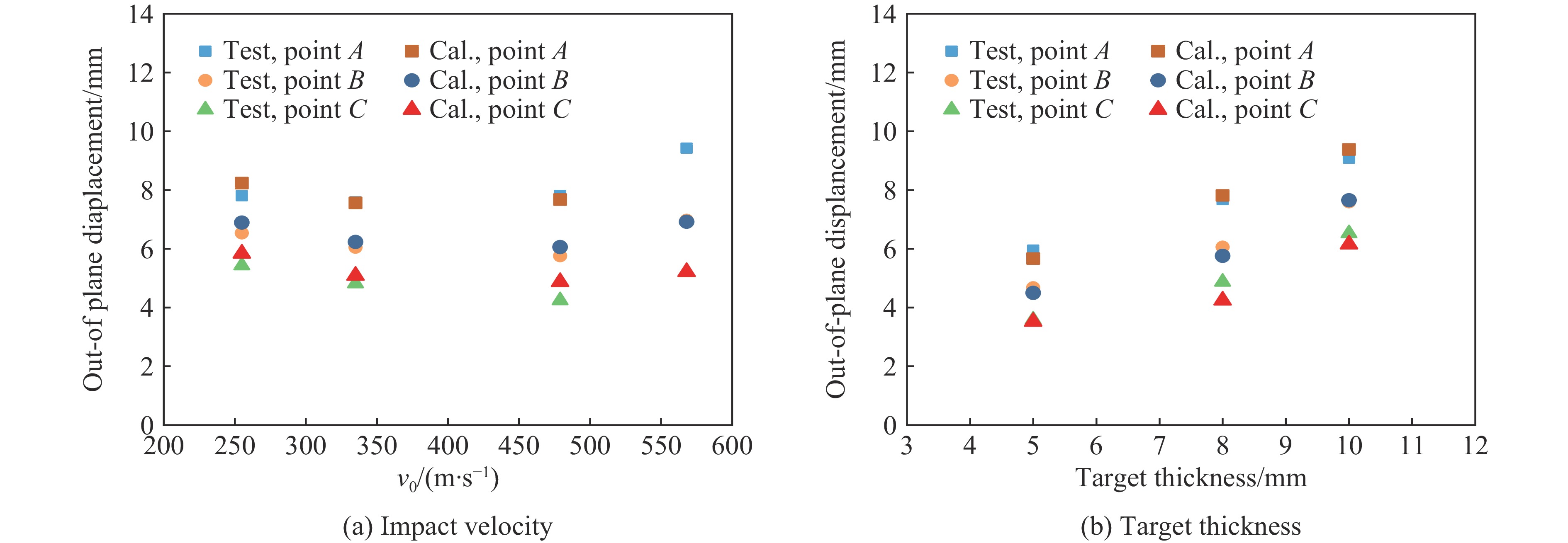
图 15 离面位移随冲击速度和靶板厚度的变化
Figure 15. Variations of out-of-plane displacements with impact velocities and target thicknesses
表 1 试验数据
Table 1. Test data
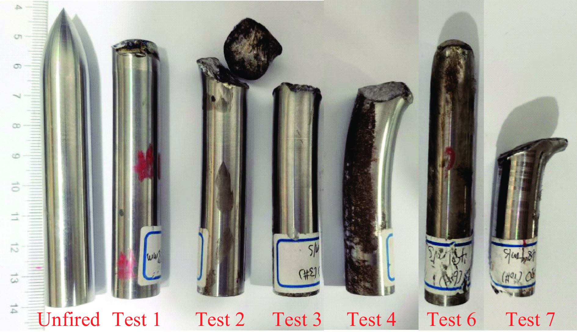
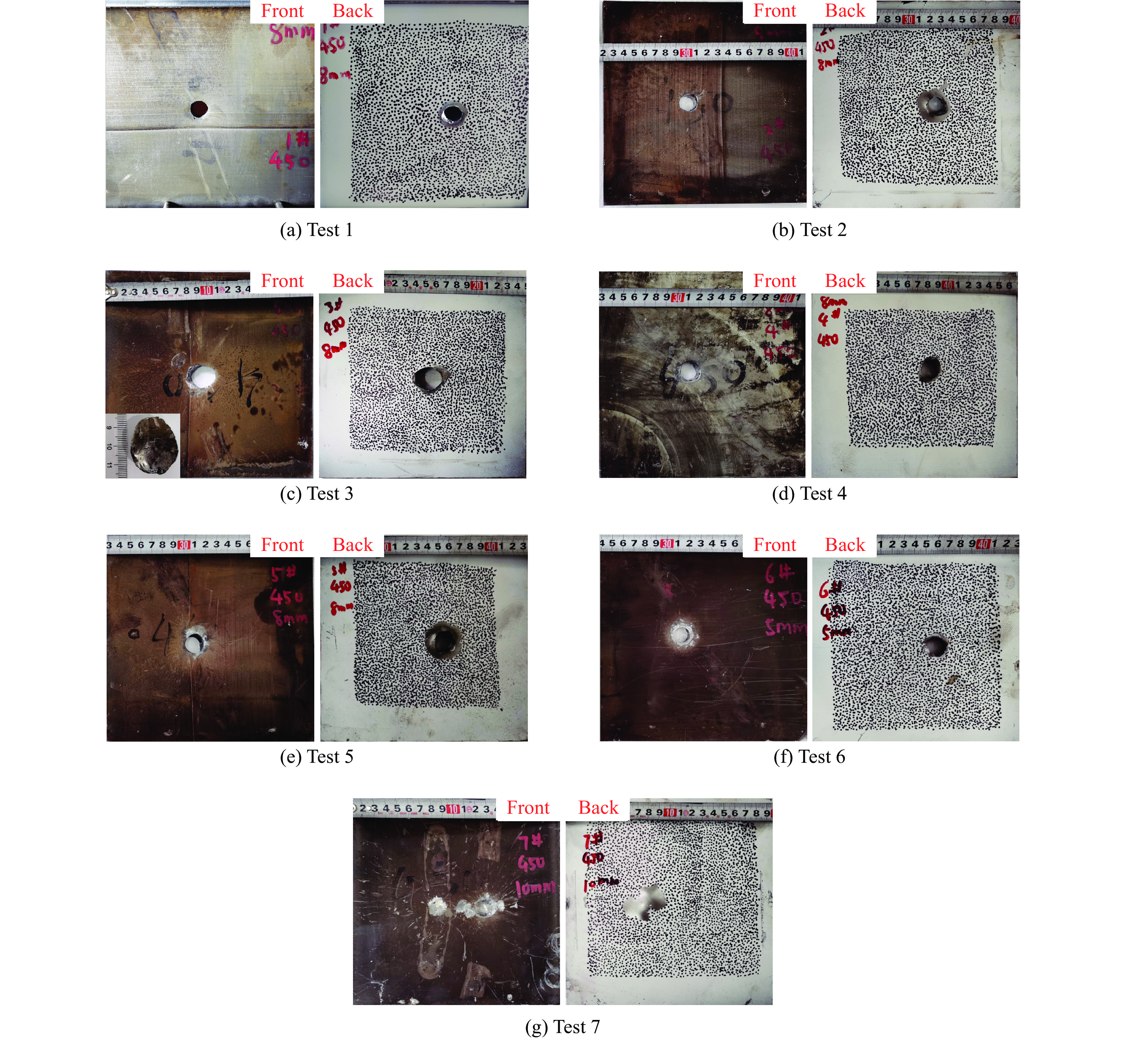
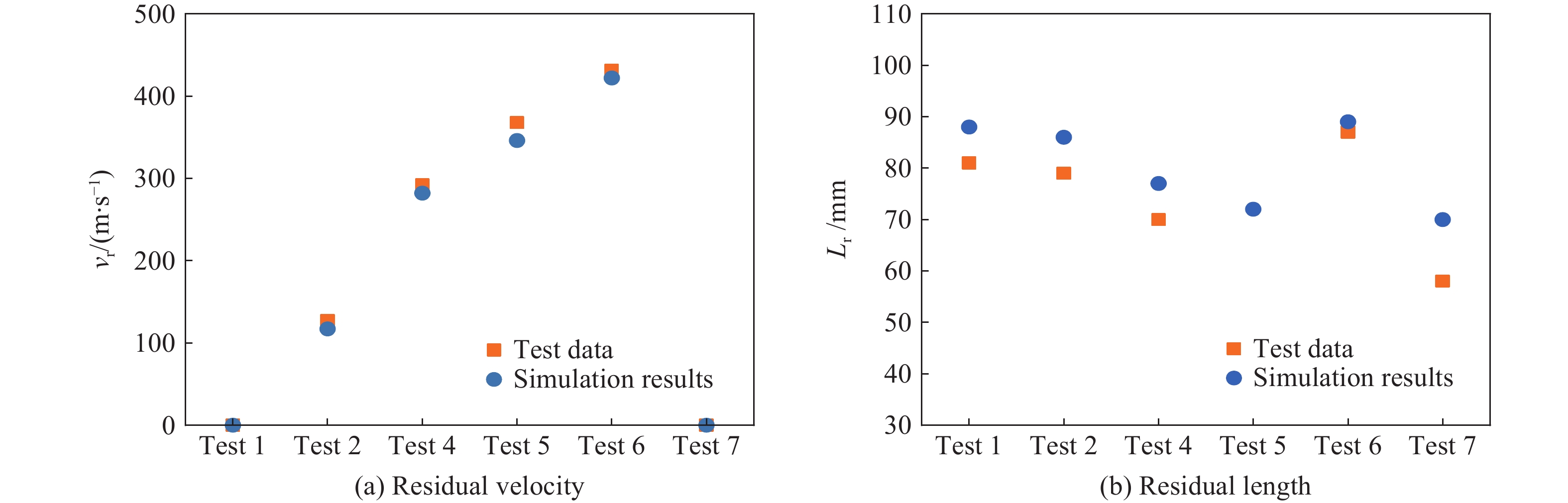
试验 板厚/mm v0/(m·s−1) vr/(m·s−1) Mr/g Lr/mm 1 8 255 0 109.4 81 2 8 335 127 109.6 79 3 8 406 111 91.0 67 4 8 479 292 95.3 70 5 8 568 368 − − 6 5 491 431 112.4 87 7 10 489 − 73.5 58  下载: 导出CSV
表 2 三个位置点处不同时刻的离面位移
Table 2. The out-of-plane displacement of three points at various times
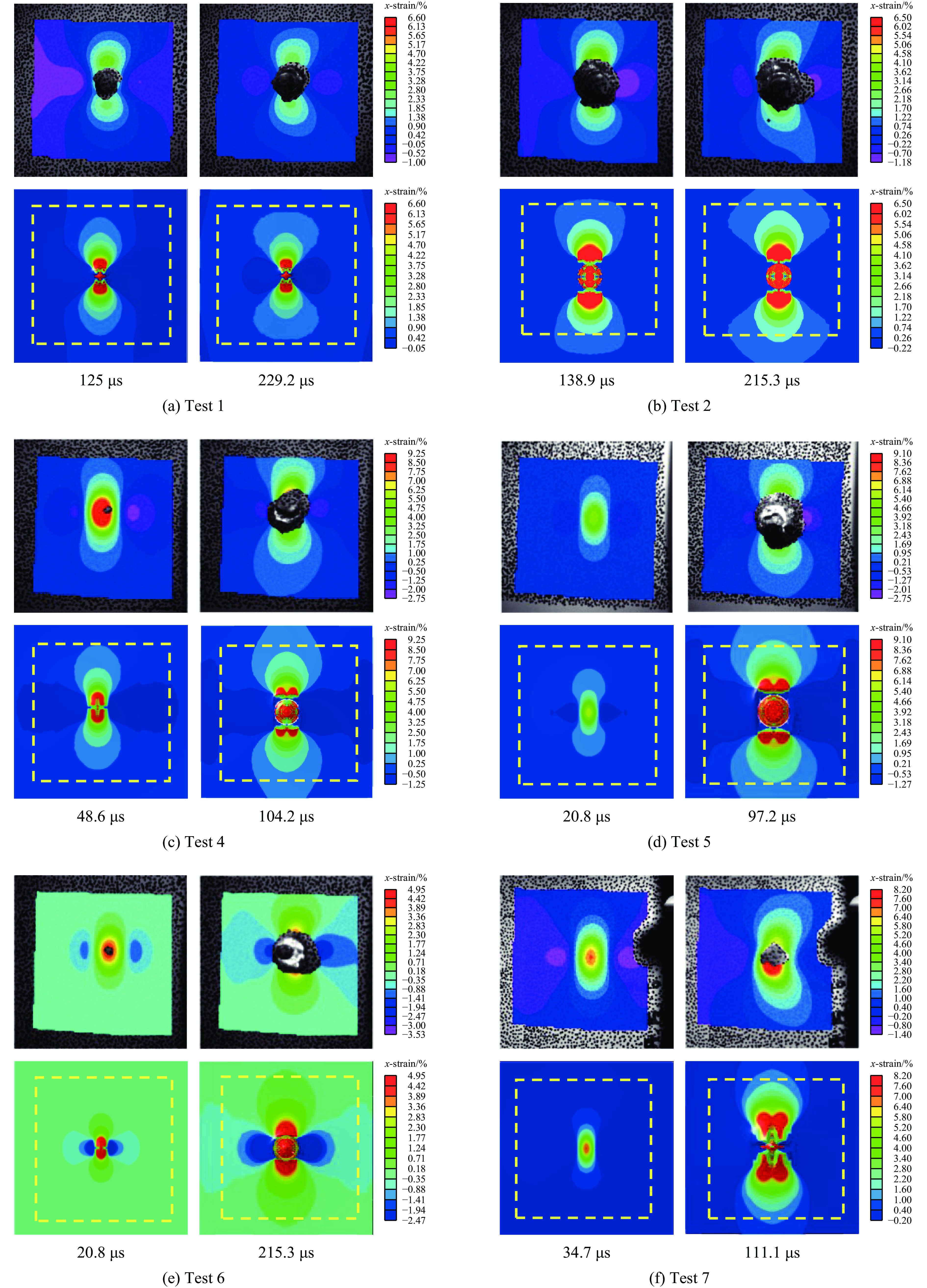
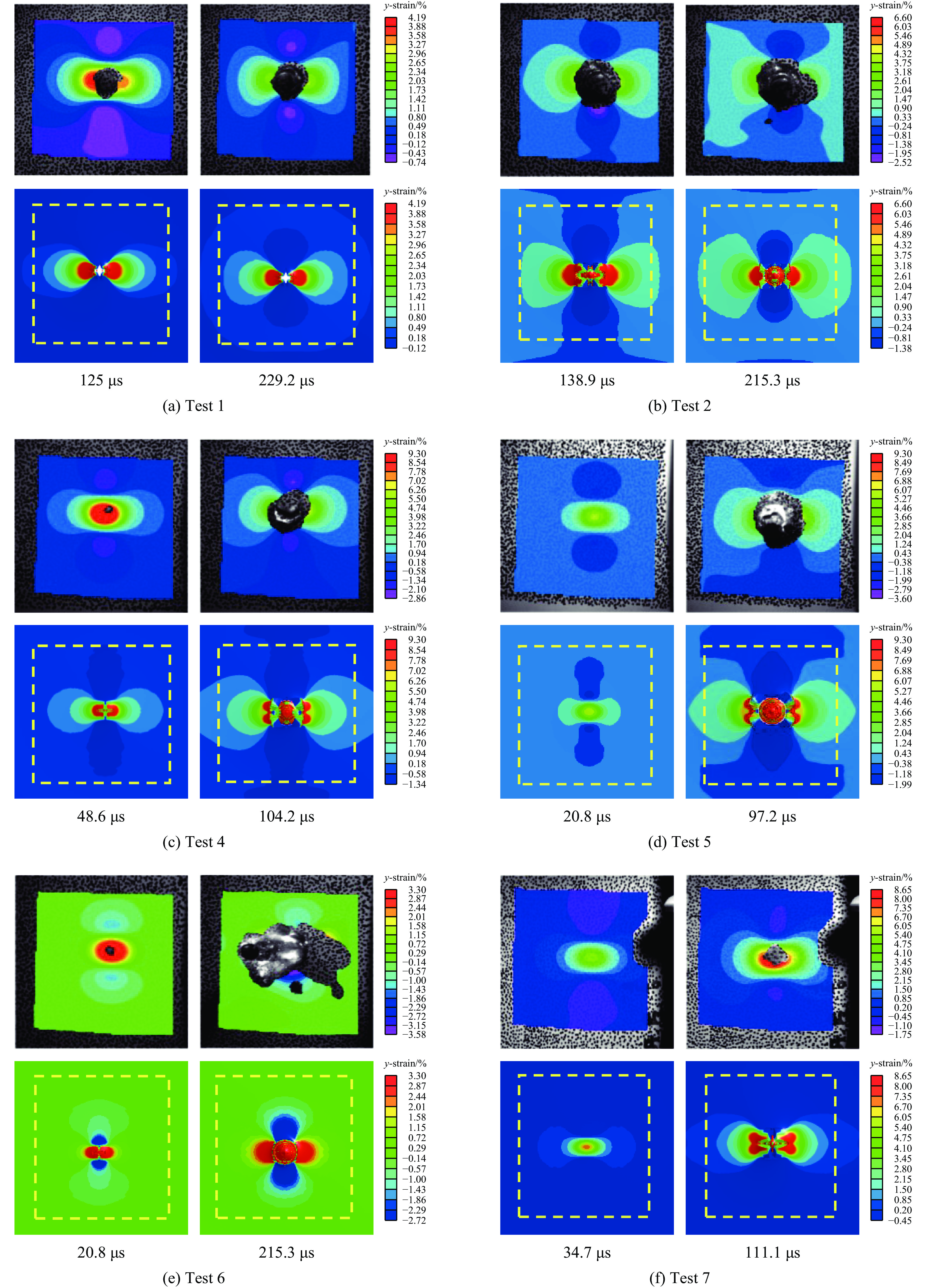
试验 Out-of-plane displacement/mm 62.5 μs 125 μs 173.6 μs 点 A 点 B 点 C 点 A 点 B 点 C 点 A 点 B 点 C 1 1.536 0.829 0.365 4.848 3.376 2.301 6.302 4.961 3.932 2 2.555 1.359 0.560 5.677 4.076 2.699 6.593 5.213 4.070 4 3.237 1.665 0.702 5.856 4.186 2.947 6.813 5.306 4.202 5 4.906 2.461 1.014 − 5.043 3.704 − 6.156 4.887 6 2.981 1.659 0.352 − 2.979 1.674 4.330 3.519 2.319 7 3.237 2.077 1.290 6.791 5.395 4.313 8.503 7.070 6.008 注:“−”表示由于散斑脱落导致无法读取位移值。
下载: 导出CSV
表 3 弹靶J-C本构模型参数
Table 3. J-C constitutive model parameters of projectile and target
强度参数 损伤参数 状态方程参数 A/MPa B/MPa n C m D1 D2 D3 D4 D5 c/(m∙s−1) s1 s2,s3 γ0 a 1230 1647 0.4985 0.013 1.0 0.696 1.827 −2.184 −0.05 0 4578 1.33 0 1.67 0.43
下载: 导出CSV
-
[1] FRAS T, ROTH C C, MOHR D. Fracture of high-strength armor steel under impact loading [J]. International Journal of Impact Engineering, 2018, 111: 147–164. DOI: 10.1016/j.ijimpeng.2017.09.009. [2] FRAS T, ROTH C C, MOHR D. Dynamic perforation of ultra-hard high-strength armor steel: impact experiments and modeling [J]. International Journal of Impact Engineering, 2019, 131: 256–271. DOI: 10.1016/j.ijimpeng.2019.05.008. [3] CHOUDHARY S, SINGH P K, KHARE S, et al. Ballistic impact behaviour of newly developed armour grade steel: an experimental and numerical study [J]. International Journal of Impact Engineering, 2020, 140: 103557. DOI: 10.1016/j.ijimpeng.2020.103557. [4] CHEVALIER L, CALLOCH S, HILD F, et al. Digital image correlation used to analyze the multiaxial behavior of rubber-like materials [J]. European Journal of Mechanics - A/Solids, 2001, 20(2): 169–187. DOI: 10.1016/S0997-7538(00)01135-9. [5] MENG S Q, LI J M, LIU Z H, et al. Study of flexural and crack propagation behavior of layered fiber-reinforced cementitious mortar using the digital image correlation (DIC) technique [J]. Materials, 2021, 14(6): 4700. DOI: 10.3390/ma14164700. [6] 杨洋, 孙炜, 王亮, 等. 基于DIC方法的TC4钛合金高温拉伸试验 [J]. 材料热处理学报, 2021, 42(2): 44–51. DOI: 10.13289/j.issn.1009-6264.2020-0378.YANG Y, SUN W, WANG L, et al. High temperature tensile test of TC4 titanium alloy based on digital image correlation method [J]. Transactions of Materials and Heat Treatment, 2021, 42(2): 44–51. DOI: 10.13289/j.issn.1009-6264.2020-0378. [7] 陈学文, 白荣忍, 刘佳琪, 等. 基于数字图像相关技术的X12合金钢高温损伤模型试验验证方法 [J]. 材料热处理学报, 2021, 42(8): 163–169. DOI: 10.13289/j.issn.1009-6264.2021-0073.CHEN X W, BAI R R, LIU J Q, et al. High temperature damage model test verification method of X12 alloy steel based on digital image correlation technology [J]. Transactions of Materials and Heat Treatment, 2021, 42(8): 163–169. DOI: 10.13289/j.issn.1009-6264.2021-0073. [8] 徐纪鹏, 董新龙, 付应乾, 等. 不同加载边界下混凝土巴西劈裂过程及强度的DIC实验分析 [J]. 力学学报, 2020, 52(3): 864–876. DOI: 10.6052/0459-1879-19-303.XU J P, DONG X L, FU Y Q, et al. Experimental analysis of process and tensile strength for concrete Brazilian splitting test with different loading boundaries by DIC method [J]. Chinese Journal of Theoretical and Applied Mechanics, 2020, 52(3): 864–876. DOI: 10.6052/0459-1879-19-303. [9] 杨国梁, 毕京九, 郭伟民, 等. 加载角度对层理页岩裂纹扩展影响的实验研究 [J]. 爆炸与冲击, 2021, 41(9): 093101. DOI: 10.11883/bzycj-2021-0097.YANG G L, BI J J, GUO W M, et al. Experimental study on the effect of loading angle on crack propagation in bedding shale [J]. Explosion and Shock Waves, 2021, 41(9): 093101. DOI: 10.11883/bzycj-2021-0097. [10] 宋海鹏, 刘长春. 基于数字图像相关的预腐蚀2024-T4铝合金疲劳开裂实验 [J]. 航空材料学报, 2020, 40(2): 43–52. DOI: 10.11868/j.issn.1005-5053.2019.000164.SONG H P, LIU C C. Experimental study on fatigue cracking in pre-corroded aluminum alloy 2024-T4 via digital image correlation [J]. Journal of Aeronautical Materials, 2020, 40(2): 43–52. DOI: 10.11868/j.issn.1005-5053.2019.000164. [11] PAN B, YU L P, YANG Y Q, et al. Full-field transient 3D deformation measurement of 3D braided composite panels during ballistic impact using single-camera high-speed stereo-digital image correlation [J]. Composite Structures, 2016, 157: 25–32. DOI: 10.1016/j.compstruct.2016.08.017. [12] 徐振洋, 杨军, 郭连军. 爆炸聚能作用下混凝土试件劈裂的高速3D DIC实验 [J]. 爆炸与冲击, 2016, 36(3): 400–406. DOI: 10.11883/1001-1455(2016)03-0400-07.XU Z Y, YANG J, GUO L J. Study of the splitting crack propagation morphology using high-speed 3D DIC [J]. Explosion and Shock Waves, 2016, 36(3): 400–406. DOI: 10.11883/1001-1455(2016)03-0400-07. [13] ROLFE E, KABOGLU C, QUINN R, et al. High velocity impact and blast loading of composite sandwich panels with novel carbon and glass construction [J]. Journal of Dynamic Behavior of Materials, 2018, 4(3): 359–372. DOI: 10.1007/s40870-018-0163-5. [14] XING H Z, ZHAO J, WU G, et al. Perforation model of thin rock slab subjected to rigid projectile impact at an intermediate velocity [J]. International Journal of Impact Engineering, 2020, 139: 103536. DOI: 10.1016/j.ijimpeng.2020.103536. [15] 魏宏健, 姜雄文, 赵庚, 等. 爆炸冲击波载荷下预制孔铝板的动态响应 [J]. 兵工学报, 2021, 42(S1): 96–104. DOI: 10.3969/j.issn.1000-1093.2021.S1.013.WEI H J, JIANG X W, ZHAO G, et al. Dynamic response of aluminum plates with pre-formed holes under airblast loading [J]. Acta Armamentarii, 2021, 42(S1): 96–104. DOI: 10.3969/j.issn.1000-1093.2021.S1.013. [16] LIU X, YANG J, XU Z Y, et al. Experimental investigations on crack propagation characteristics of granite rectangle plate with a crack (GRPC) under different blast loading rates [J]. Shock and Vibration, 2020, 2020: 8885582. DOI: 10.1155/2020/8885582. [17] 范亚夫, 魏延鹏, 薛跃军, 等. 数字图像相关测试技术在霍普金森杆加载实验中的应用 [J]. 实验力学, 2015, 30(5): 590–598. DOI: 10.7520/1001-4888-14-273.FAN Y F, WEI Y P, XUE Y J, et al. On the application of digital image correlation testing technology in Hopkinson bar loading [J]. Journal of Experimental Mechanics, 2015, 30(5): 590–598. DOI: 10.7520/1001-4888-14-273. [18] 邢灏喆, 王明洋, 范鹏贤, 等. 基于高速3D-DIC技术的砂岩动力特性粒径效应研究 [J]. 爆炸与冲击, 2021, 41(11): 113101. DOI: 10.11883/bzycj-2021-0088.XING H Z, WANG M Y, FAN P X, et al. Grain-size effect on dynamic behavior of sandstone based on high-speed 3D-DIC technique [J]. Explosion and Shock Waves, 2021, 41(11): 113101. DOI: 10.11883/bzycj-2021-0088. [19] ATAPEK S H, KARAGOZ S. Ballistic impact behaviour of a tempered bainitic steel against 7.62 mm armour piercing projectile [J]. Defence Science Journal, 2011, 61(1): 81–87. DOI: 10.14429/dsj.61.411. [20] BURIAN W, ŻOCHOWSKI P, GMITRZUK M, et al. Protection effectiveness of perforated plates made of high strength steel [J]. International Journal of Impact Engineering, 2019, 126: 27–39. DOI: 10.1016/j.ijimpeng.2018.12.006. [21] 程月华, 吴昊, 谭可可, 等. 装甲钢/UHPC复合靶体抗侵彻性能试验与数值模拟研究 [J]. 爆炸与冲击, 2022, 42(5): 053302. DOI: 10.11883/bzycj-2021-0278.CHENG Y H, WU H, TAN K K, et al. Experimental and numerical studies on penetration resistance of armor steel/UHPC composite targets [J]. Explosion and Shock Waves, 2022, 42(5): 053302. DOI: 10.11883/bzycj-2021-0278. [22] Livermore Software Technology Corporation. LS-DYNA keyword user’s manual [Z]. Livermore: Livermore Software Technology Corporation, 2001. [23] JOHNSON G R, COOK W H. A constitutive model and data for metals subjected to large strains, high strain rates and high temperatures [C]//Proceedings of the 7th International Symposium on Ballistics. Hague, 1983. [24] JOHNSON G R, COOK W H. Fracture characteristics of three metals subjected to various strains, strain rates, temperatures and pressures [J]. Engineering Fracture Mechanics, 1985, 21(1): 31–48. DOI: 10.1016/0013-7944(85)90052-9. [25] STEINBERG D J. Equation of state and strength properties of selected materials [M]. Livermore: Lawrence Livermore National Laboratory, 1996. [26] IQBAL D, TIWARI V. Investigations on the influence of projectile shape on the transient and post impact response of thin sheet structures [J]. Thin-Walled Structures, 2019, 145: 106402. DOI: 10.1016/j.tws.2019.106402. 期刊类型引用(4)
1. 吴琼,何斌策,张兴振. 基于数字图像相关技术的大尺寸叶片动态全场应变测量. 理化检验-物理分册. 2025(02): 26-30 .  百度学术
百度学术2. 闫松,张志伟. 基于3D-SLDV和高速3D-DIC的离心轮模态分析. 火箭推进. 2024(02): 107-112 . 百度学术3. 张一鸣,李广,徐自力,王珺,闫松. 融入几何先验的圆柱表面三维应变场双目视觉测量方法. 西安交通大学学报. 2024(06): 162-173 . 百度学术4. 袁治未,陈爱军,林杰俊,胡佳成,蔡晋辉. 基于2D-DIC的轴体扭矩测量方法. 现代电子技术. 2024(21): 165-170 . 百度学术其他类型引用(5)
-

 下载:
下载:


 百度学术
百度学术
计量
- 文章访问数: 694
- HTML全文浏览量: 210
- PDF下载量: 179
- 被引次数: 9