


Research progress of shock induced polarization effect in solid mediums
-
摘要: 冲击波在固体介质内传播时,内部电荷随冲击波作用向两极迁移形成电势差并对外输出电压/电流的极化效应称作冲击极化效应。针对晶体、金属、陶瓷以及聚合物等典型固体介质的冲击极化效应进行了系统梳理;总结了现阶段发展的冲击极化测试方法,分析了落锤/摆锤、SHPB、轻气炮以及炸药爆轰等加载方式诱发固体介质极化响应的差异;概述了有限元方法、分子动力学、近场动力学方法以及相场分析方法在固体介质冲击极化数值模拟领域的应用;围绕Allison理论、张裕恒理论、冲击挠曲电理论以及冲击波相关理论,总结了固体介质冲击极化的宏观唯象理论,并从固体介质微观结构、载流子输运模式、输运模型、迁移率以及态密度等方面说明了冲击极化的微观机理;分析了冲击极化效应在传感器、俘能器以及致动器等领域的应用前景,对固体介质冲击极化效应的发展趋势和需求进行了展望。Abstract: When shock waves propagate in solid mediums, the internal charge carriers migrate to the electrodes under the action of shock waves to form electric potential and output voltage/current -shock induced polarization (SIP) effect. The development of SIP effect has challenged the traditional understanding of physical response of solid medium. In this paper, the SIP effects of typical solid mediums such as crystals, metals, ceramics and polymers are systematically reviewed. The SIP test methods developed at present are also summarized, and the characteristics of SIP induced by different loading methods such as drop hammer/pendulum, SHPB, light gas gun and explosive detonation are analyzed. The applications of finite element method, molecular dynamics, peridynamic and phase field analysis in the numerical simulation of SIP of solid mediums are summarized. The macroscopic phenomenology theories of SIP of solid mediums are summarized based on Allison theory, Zhang Yuheng theory, shock flexoelectric theory and shock wave theory, and the microscopic mechanism of SIP is explained considering the microstructure of solid medium, carrier transport mode, transport model, mobility and state density. Furthermore, the application prospect of SIP effect in sensors, energy harvesters and actuators are analyzed, also, the development trend and demand of SIP in solid media are also prospected.
-
Key words:
- shock induced polarization /
- solid medium /
- charge carriers /
- shock wave
-


图 13 PDMS动态力电响应测试系统
Figure 13. Dynamic electromechanical response testing system of PDMS


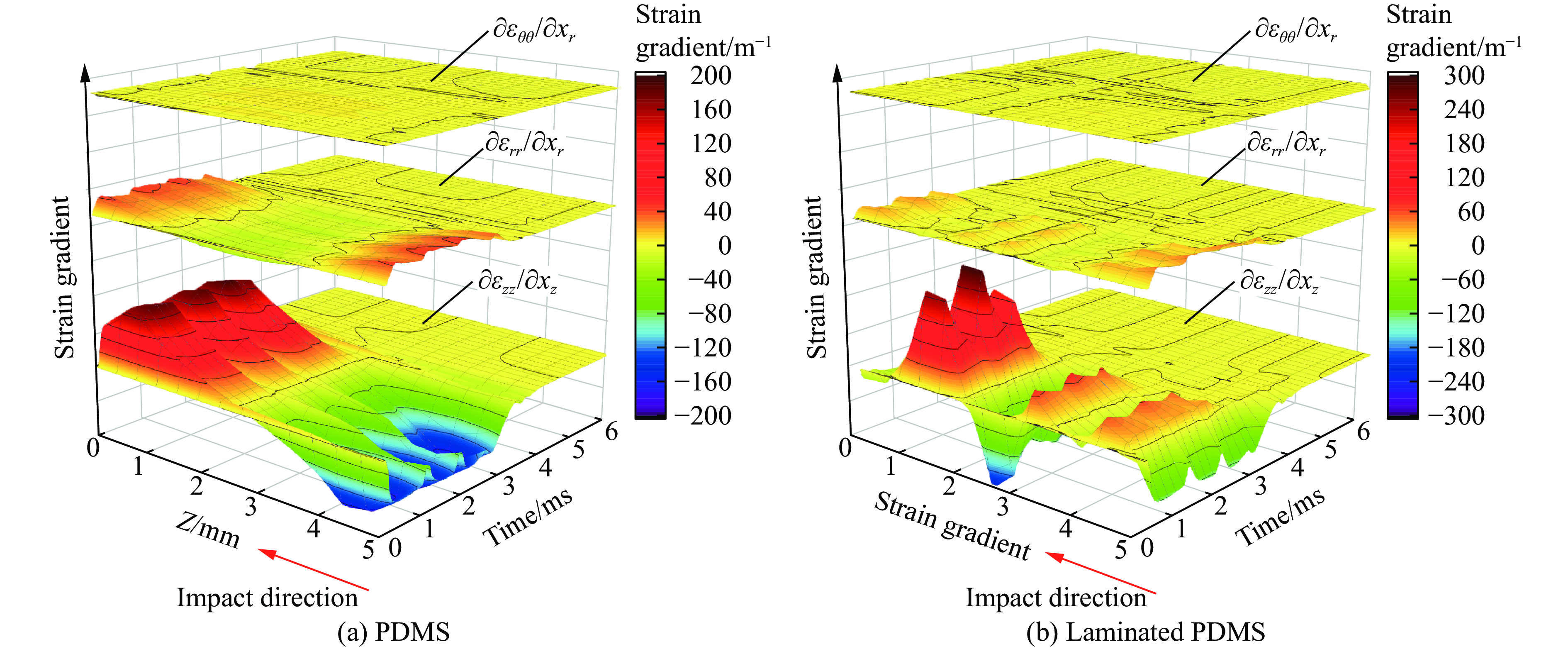
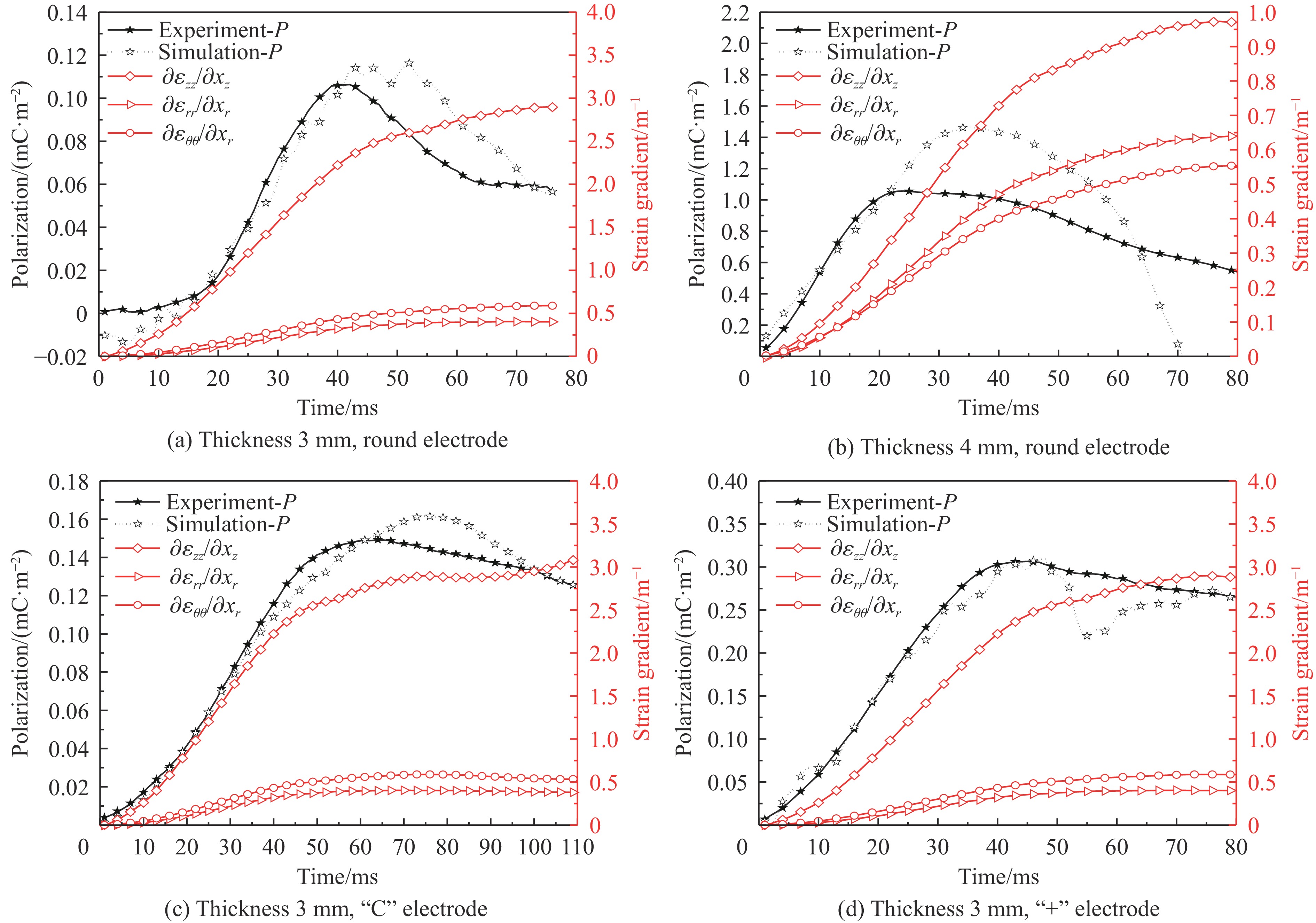
图 22 平均应变梯度的时空分布规律
Figure 22. Spatial and temporal distribution of average strain gradient


表 1 典型动态加载技术的特点
Table 1. Characteristics of typical dynamic loading technology
实验方法 应变率/s−1 响应特性 主要应用 落锤/摆锤 1~102 弹塑性变形,伴随损伤破坏 测定抗冲击强度、变形与吸能 SHPB 102~104 弹塑相变,黏性与应变率效应明显 确定动态本构模型 轻气炮 104~106 出现流体性态,考虑密度与可压缩性 确定状态方程 爆轰 >106 呈流体力学状态,伴有熔融与汽化 可计算爆轰波,确定状态方程  下载: 导出CSV
-
[1] LINDE R K, MURRI W J, DORAN D G. Shock-induced electrical polarization of alkali halides [J]. Journal of Applied Physics, 1966, 37(7): 2527–2532. DOI: 10.1063/1.1782079. [2] NABATOV S S, YAKUSHEV V V, DREMIN A N. Shock-induced electrical polarization of nitroglycerine [J]. Combustion, Explosion and Shock Waves, 1976, 12(2): 222–226. DOI: 10.1007/bf00744892. [3] KURTO A P, ANTIPENKO A G, DREMIN A N, et al. Shock-wave-induced electrical polarization of polyvinyl chloride plastic [J]. Combustion, Explosion and Shock Waves, 1983, 19(5): 682–685. DOI: 10.1007/bf00750459. [4] ANTIPENKO A G, DREMIN A N, NABATOV S S, et al. Electrical effects in shock compression and detonation of liquid high explosives [J]. Combustion, Explosion and Shock Waves, 1975, 11(3): 371–375. DOI: 10.1007/bf00740546. [5] IVANOV A G, MINEEV V N, NOVITSKII E Z, et al. Electrical effects associated with shock loading [J]. Combustion, Explosion and Shock Waves, 1969, 5(4): 356–360. DOI: 10.1007/bf00742077. [6] ALLISON F E. Shock-induced polarization in plastics. Ⅰ. Theory [J]. Journal of Applied Physics, 1965, 36(7): 2111–2113. DOI: 10.1063/1.1714428. [7] TAGANTSEV A K. Pyroelectric, piezoelectric, flexoelectric, and thermal polarization effects in ionic crystals [J]. Soviet Physics Uspekhi, 1987, 30(7): 588–603. DOI: 10.1070/pu1987v030n07abeh002926. [8] CHEN Z, HUANG K M. Using the oscillating dipoles model to study the electromagnetic radiation induced by fracture of rocks [J]. Progress in Electromagnetics Research M, 2010, 14: 221–231. DOI: 10.2528/PIERM10041802. [9] MINEEV V N, IVANOV A G. Electromotive force produced by shock compression of a substance [J]. Soviet Physics Uspekhi, 1976, 19(5): 400. DOI: 10.1070/PU1976v019n05ABEH005260. [10] TYUNYAEV Y N, MINEEV V N, IVANOV A G, et al. Connection between shock polarization of ionic crystals and the lattice characteristics [J]. Soviet Physics JETP, 1969, 29(1): 98–100. [11] COLEBURN N L, FORBES J W, JONES H D. Electrical measurements in silicon under shock-wave compression [J]. Journal of Applied Physics, 1972, 43(12): 5007–5012. DOI: 10.1063/1.1661061. [12] MISRA A. A physical model for the stress-induced electromagnetic effect in metals [J]. Applied Physics, 1978, 16(2): 195–199. DOI: 10.1007/bf00930387. [13] TANG E L, LIU P, WANG R Z, et al. Polarization response characteristics of 6061Al under impact loading [J]. Journal of Materials Science: Materials in Electronics, 2023, 34(24): 1732. DOI: 10.1007/s10854-023-11135-w. [14] TANG E L, WANG D B, LI L, et al. Polarization response characteristics of 6061Al and PMMA sheets under impact load [J]. International Journal of Impact Engineering, 2023, 178: 104632. DOI: 10.1016/j.ijimpeng.2023.104632. [15] SETCHELL R E. Recent progress in understanding the shock response of ferroelectric ceramics [J]. AIP Conference Proceedings, 2002, 620(1): 191–196. DOI: 10.1063/1.1483513. [16] HALPIN W J. Current from a shock-loaded short-circuited ferroelectric ceramic disk [J]. Journal of Applied Physics, 1966, 37(1): 153–163. DOI: 10.1063/1.1707798. [17] LYSNE P C, PERCIVAL C M. Electric energy generation by shock compression of ferroelectric ceramics: normal-mode response of PZT 95/5 [J]. Journal of Applied Physics, 1975, 46(4): 1519–1525. DOI: 10.1063/1.321803. [18] LYSNE P C, PERCIVAL C M. Analysis of shock-wave-actuated ferroelectric power supplies [J]. Ferroelectrics, 1976, 10(1): 129–133. DOI: 10.1080/00150197608241963. [19] LYSNE P C. Shock-induced polarization of a ferroelectric ceramic [J]. Journal of Applied Physics, 1977, 48(3): 1024–1031. DOI: 10.1063/1.323802. [20] FURNISH M D, CHHABILDAS L C, SETCHELL R E, et al. Dynamic electromechanical characterization of axially poled PZT 95/5 [J]. AIP Conference Proceedings, 2000, 505(1): 975–978. DOI: 10.1063/1.1303631. [21] MOCK JR W, HOLT W H. Analysis of the ideal response of shock-depoled ferroelectric ceramics [J]. Ferroelectrics, 1980, 23(1): 39–45. DOI: 10.1080/00150198008224809. [22] 贺元吉, 张亚洲, 李传胪, 等. 冲击波加载下PZT 95/5铁电陶瓷电响应的数值模拟 [J]. 高压物理学报, 2000, 14(3): 189–194. DOI: 10.11858/gywlxb.2000.03.006.HE Y J, ZHANG Y Z, LI C L, et al. The numerical simulation of electric response of PZT 95/5 ferroelectric ceramics subjected to shock loading [J]. Chinese Journal of High Pressure Physics, 2000, 14(3): 189–194. DOI: 10.11858/gywlxb.2000.03.006. [23] MASHIMO T, TODA K, NAGAYAMA K, et al. Electrical response of BaTiO3 ceramics to the shock-induced ferroelectric-paraelectric transition [J]. Journal of Applied Physics, 1986, 59(3): 748–756. DOI: 10.1063/1.336595. [24] 刘高旻, 杜金梅, 刘雨生, 等. PZT 95/5铁电陶瓷的冲击压缩Hugoniot特性研究 [J]. 高压物理学报, 2008, 22(1): 30–34. DOI: 10.11858/gywlxb.2008.01.007.LIU G M, DU J M, LIU Y S, et al. Shock wave compression of PZT 95/5 ferroelectric ceramic [J]. Chinese Journal of High Pressure Physics, 2008, 22(1): 30–34. DOI: 10.11858/gywlxb.2008.01.007. [25] PENG P, NIE H C, WANG G S, et al. Shock-driven depolarization behavior in BNT-based lead-free ceramics [J]. Applied Physics Letters, 2018, 113(8): 082901. DOI: 10.1063/1.5045392. [26] GAO Z P, PENG W, CHEN B, et al. Giant power output in lead-free ferroelectrics by shock-induced phase transition [J]. Physical Review Materials, 2019, 3(3): 035401. DOI: 10.1103/physrevmaterials.3.035401. [27] TANG E L, LENG B Y, HAN Y F, et al. Influence of temperature on electromechanical responses of PZT-5H and output energy under shock loading [J]. Materials Chemistry and Physics, 2022, 276: 125309. DOI: 10.1016/j.matchemphys.2021.125309. [28] HAUVER G E. Erratum: Shock-induced polarization in plastics. Ⅱ. Experimental study of plexiglas and polystyrene [J]. Journal of Applied Physics, 1965, 36(7): 2113–2118. DOI: 10.1063/1.1714429. [29] ANTINENKO A G, NABATOV S S, YAKUSHEV V V. Electrical polarization of an insulator with fast relaxation on shock compression [J]. Combustion, Explosion and Shock Waves, 1975, 11(3): 391–394. DOI: 10.1007/bf00740549. [30] GONCHAROV A I, SOLOVIEV S P. Shock-induced polarization of materials [J]. Combustion, Explosion and Shock Waves, 2004, 40(6): 658–662. DOI: 10.1023/b:cesw.0000048267.04438.cc. [31] LYSNE P C. Dielectric properties of shock-wave-compressed PMMA and an alumina-loaded epoxy [J]. Journal of Applied Physics, 1978, 49(7): 4186–4190. DOI: 10.1063/1.325330. [32] TOWNSEND D, BOURNE N K. Measurements of the conductivity of shocked polymethylmethacrylate [J]. AIP Conference Proceedings, 2002, 620(1): 1267–1272. DOI: 10.1063/1.1483770. [33] CHANG M Z, LI K, LIU C, et al. Coupling effect of impact and in-layer voltage on flexoelectricity of PDMS laminated structures [J]. Polymer Testing, 2022, 115: 107741. DOI: 10.1016/j.polymertesting.2022.107741. [34] IVANOV A G, TYUNYAEV Y N, MINEEV V N, et al. Conductivity transition zone and polarization of TNT behind the shock front [J]. Combustion, Explosion, and Shock Waves, 1969, 5(3): 256–262. DOI: 10.1007/bf00748604. [35] 张阳. 乳化炸药微观结构变化对电导率影响的探究 [D]. 淮南: 安徽理工大学, 2015. DOI: 10.7666/d.Y2767930.ZHANG Y. Study on the influence of microstructure change of emulsion explosive on conductivity [D]. Huainan: Anhui University of Science and Technology, 2015. DOI: 10.7666/d.Y2767930. [36] ANTIPENKO A G, DREMIN A N, YAKUSHEV V V. Electrical polarization with initiation of the detonation of homogeneous explosives by a shock wave [J]. Combustion, Explosion, and Shock Waves, 1978, 14(6): 786–790. DOI: 10.1007/bf00786113. [37] 蒋治海, 龙新平, 何碧, 等. TNT和RHT-906炸药起爆过程的电导率研究 [J]. 含能材料, 2007, 15(2): 169–171. DOI: 10.3969/j.issn.1006-9941.2007.02.022.JIANG Z H, LONG X P, HE B, et al. Electrical conductivity of TNT and RHT-906 explosives in initiation process [J]. Chinese Journal of Energetic Materials, 2007, 15(2): 169–171. DOI: 10.3969/j.issn.1006-9941.2007.02.022. [38] HWANG M Y, KANG L H. Characteristics and fabrication of piezoelectric GFRP using smart resin prepreg for detecting impact signals [J]. Composites Science and Technology, 2018, 167: 224–233. DOI: 10.1016/j.compscitech.2018.08.002. [39] CUTHRELL R E. Epoxy polymers. IV. Impact-induced voltage generation [J]. Journal of Applied Polymer Science, 1968, 12(7): 1515–1530. DOI: 10.1002/app.1968.070120703. [40] HU T T, WANG X Z, YAN Y B, et al. Influence of impact velocity on flexoelectric effect [J]. Results in Physics, 2019, 15: 102812. DOI: 10.1016/j.rinp.2019.102812. [41] CHAMPION A R. Electrical response of anodized aluminum layers to shock-wave compression [J]. Journal of Applied Physics, 1969, 40(9): 3766–3771. DOI: 10.1063/1.1658269. [42] 甄广平, 陈福梅. 层状有机玻璃PMMA的冲击极化效应与应用 [J]. 北京理工大学学报, 1992, 12(2): 16–24.ZHEN G P, CHEN F M. Shock induced polarization of laminate PMMA and its application [J]. Journal of Beijing Institute of Technology, 1992, 12(2): 16–24. [43] 张春生. 一种改进的冲击极化实验装置 [J]. 爆炸与冲击, 1986, 6(1): 67–71.ZHANG C S. An improved experimental setup for shock-induced polarization [J]. Explosion and Shock Waves, 1986, 6(1): 67–71. [44] SAXENA K, HIRONAKA Y, HIRAI H, et al. Shock-induced polarization in normal-hexane [J]. Applied Physics Letters, 1996, 68(7): 920–922. DOI: 10.1063/1.116231. [45] 潘锴. 针对PFM技术的铁电材料纳米尺度力电耦合分析 [D]. 湘潭: 湘潭大学, 2014. DOI: 10.7666/d.D583513.PAN K. Analyzing nanoscale electromechanical coupling of ferroelectrics as probed by PFM [D]. Xiangtan: Xiangtan University, 2014. DOI: 10.7666/d.D583513. [46] KAJIMOTO K, ARAKI K, USAMI Y, et al. Visualization of charge migration in conductive polymers via time-resolved electrostatic force microscopy [J]. The Journal of Physical Chemistry A, 2020, 124(25): 5063–5070. DOI: 10.1021/acs.jpca.9b12017. [47] CODONY D, GUPTA P, MARCO O, et al. Modeling flexoelectricity in soft dielectrics at finite deformation [J]. Journal of the Mechanics and Physics of Solids, 2021, 146: 104182. DOI: 10.1016/j.jmps.2020.104182. [48] MENG J, ZHANG Y W, HOLÉ S, et al. Charge mobility retrieval approach from apparent charge packet movements based on the negative differential resistance theory [J]. Scientific Reports, 2018, 8(1): 5928. DOI: 10.1038/s41598-018-24327-w. [49] HONG J W, CATALAN G, SCOTT J F, et al. The flexoelectricity of barium and strontium titanates from first principles [J]. Journal of Physics: Condensed Matter, 2010, 22(11): 112201. DOI: 10.1088/0953-8984/22/11/112201. [50] HONG J W, VANDERBILT D. First-principles theory of frozen-ion flexoelectricity [J]. Physical Review B, 2011, 84(18): 180101. DOI: 10.1103/PhysRevB.84.180101. [51] HONG J W, VANDERBILT D. First-principles theory and calculation of flexoelectricity [J]. Physical Review B, 2013, 88(17): 174107. DOI: 10.1103/PhysRevB.88.174107. [52] 李贝贝. 金属Pt和Pd的AMOEBA极化力场的构建 [D]. 大连: 辽宁师范大学, 2013. DOI: 10.7666/d.Y2376309.LI B B. A building for AMOEBA polarization force fields of metals Pt and Pd [D]. Dalian: Liaoning Normal University, 2013. DOI: 10.7666/d.Y2376309. [53] PONOMAREVA I, TAGANTSEV A K, BELLAICHE L. Finite-temperature flexoelectricity in ferroelectric thin films from first principles [J]. Physical Review B, 2012, 85(10): 104101. DOI: 10.1103/PhysRevB.85.104101. [54] ROYO M, STENGEL M. First-principles theory of spatial dispersion: dynamical quadrupoles and flexoelectricity [J]. Physical Review X, 2019, 9(2): 021050. DOI: 10.1103/physrevx.9.021050. [55] DREYER C E, STENGEL M, VANDERBILT D. Current-density implementation for calculating flexoelectric coefficients [J]. Physical Review B, 2018, 98(7): 075153. DOI: 10.1103/PhysRevB.98.075153. [56] STENGEL M. Surface control of flexoelectricity [J]. Physical Review B, 2014, 90(20): 201112. DOI: 10.1103/physrevb.90.201112. [57] HE B, JAVVAJI B, ZHUANG X Y. Size dependent flexoelectric and mechanical properties of barium titanate nanobelt: a molecular dynamics study [J]. Physica B: Condensed Matter, 2018, 545: 527–535. DOI: 10.1016/j.physb.2018.01.031. [58] TIAN X B, YANG X H, CAO W Z. Atomistic simulation of strain-induced domain evolution in a uniaxially compressed BaTiO3 single-crystal nanofilm [J]. Journal of Electronic Materials, 2013, 42(8): 2504–2509. DOI: 10.1007/s11664-013-2597-9. [59] 孙素涛. 共轭聚合物中荷电载流子动力学性质的频谱研究 [D]. 石家庄: 河北师范大学, 2020. DOI: 10.27110/d.cnki.ghsfu.2020.000586.SUN S T. Spectral analysis on charged carrier dynamics in conjugated polymers [D]. Shijiazhuang: Hebei Normal University, 2020. DOI: 10.27110/d.cnki.ghsfu.2020.000586. [60] SKRYL Y, KUKLJA M M. Numerical simulation of diffusion of electrons and holes in shocked silicon [J]. AIP Conference Proceedings, 2004, 706(1): 267–270. DOI: 10.1063/1.1780232. [61] SKRYL Y, BELAK A A, KUKLJA M M. Numerical simulation of shock induced polarization in binary electrolytes [J]. AIP Conference Proceedings, 2006, 845(1): 355–358. DOI: 10.1063/1.2263336. [62] 郭莉莉. 微观结构对铁电电畴影响机理的相场理论研究 [D]. 湘潭: 湘潭大学, 2016.GUO L L. Phase field simulation of the impact mechianism of microstructure on domain structure of ferroelectric [D]. Xiangtan: Xiangtan University, 2016. [63] CAO Y, MOROZOVSKA A, KALININ S V. Pressure-induced switching in ferroelectrics: phase-field modeling, electrochemistry, flexoelectric effect, and bulk vacancy dynamics [J]. Physical Review B, 2017, 96(18): 184109. DOI: 10.1103/physrevb.96.184109. [64] ZEL’DOVICH Y B. EMF produced by a shockwave moving in a dielectric [J]. Soviet Physics JETP, 1968, 26(1): 159–162. [65] DREMIN A N, ROZANOV O K, YAKUSHEV V V. Some problems of the polarization of dielectrics in shock waves [J]. Journal of Applied Mechanics and Technical Physics, 1968, 9(5): 562–565. DOI: 10.1007/bf02614757. [66] 冷冰玉. 6061Al与PMMA薄板的冲击极化响应规律研究 [D]. 沈阳: 沈阳理工大学, 2021. DOI: 10.27323/d.cnki.gsgyc.2022.000123.LENG B Y. Study on shock induced polarization response of 6061Al and PMMA thin plate [D]. Shenyang: Shenyang Ligong University, 2021. DOI: 10.27323/d.cnki.gsgyc.2022.000123. [67] DE ICAZA-HERRERA M. Phenomenological theory of shock-induced polarization. Ⅰ [J]. Journal of Applied Physics, 1983, 54(5): 2352–2359. DOI: 10.1063/1.332347. [68] DE ICAZA-HERRERA M. Phenomenological theory of shock-induced polarization. Ⅱ. Mathematical treatment of the oscillogram [J]. Journal of Applied Physics, 1983, 54(5): 2360–2365. DOI: 10.1063/1.332348. [69] HUANG Y J. Yuheng Zhang effect: Strain-induced electric effect in metals [J]. Journal of Materials Sciences and Applications, 2019, 5(3): 58–62. [70] HUANG Y. Strain-induced electric effects in condensed matters [J]. Journal of Materials Sciences and Application, 2019, 5(3): 44–57. [71] HADJESFANDIARI A R. Size-dependent piezoelectricity [J]. International Journal of Solids and Structures, 2013, 50(18): 2781–2791. DOI: 10.1016/j.ijsolstr.2013.04.020. [72] GARCÍA N, LEVANYUK A P, OSIPOV V V. Nature of sonoluminescence: noble gas radiation excited by hot electrons in cold water [J]. Physical Review E, 2000, 62(2): 2168–2176. DOI: 10.1103/physreve.62.2168. [73] SEDOV S Y, BORISENOK V A. Flexoelectric effect and shock-induced polarization in polar liquids [J]. Physics of Atomic Nuclei, 2019, 82(11): 1547–1551. DOI: 10.1134/s1063778819120275. [74] HU T T, DENG Q, LIANG X, et al. Measuring the flexoelectric coefficient of bulk barium titanate from a shock wave experiment [J]. Journal of Applied Physics, 2017, 122(5): 055106. DOI: 10.1063/1.4997475. [75] HARRIS P, PRESLES H N. The shock induced electrical polarization of water [J]. The Journal of Chemical Physics, 1982, 77(10): 5157–5164. DOI: 10.1063/1.443692. [76] ENIKEEV F U, KUBAREV S I, PONOMAREV O A. Orientation model of shock electrical polarization in a condensed phase [J]. Combustion, Explosion and Shock Waves, 1987, 23(4): 440–446. DOI: 10.1007/bf00749305. [77] KUBAREV S I, PONOMAREV O A, FOKIN A I. A kinetic model of shock electrical polarization [J]. Combustion, Explosion and Shock Waves, 1989, 25(3): 338–343. DOI: 10.1007/bf00788811. [78] WILHELM H E. Shock polarisation of solids between plane electrodes with external load [J]. Journal of Physics D: Applied Physics, 1982, 15(10): 2035–2043. DOI: 10.1088/0022-3727/15/10/022. [79] YAKUSHEV V V. Taking account of the no nuniformity of the dynamical loading of a sample in experiments on polarization of dielectrics under shock compression [J]. Journal of Applied Mechanics and Technical Physics, 1974, 13(4): 564–570. DOI: 10.1007/bf00850404. [80] COLLET B. Shock waves in deformable dielectrics with polarization gradients [J]. International Journal of Engineering Science, 1982, 20(10): 1145–1160. DOI: 10.1016/0020-7225(82)90095-7. [81] HARRIS P. Mechanism for the shock polarization of dielectrics [J]. Journal of Applied Physics, 1965, 36(3): 739–741. DOI: 10.1063/1.1714210. [82] HU T T, YANG W J, LIANG X, et al. Wave propagation in flexoelectric microstructured solids [J]. Journal of Elasticity, 2018, 130(2): 197–210. DOI: 10.1007/s10659-017-9636-3. [83] SALANECK W R. Conformational defects in a conducting polymer [J]. Contemporary Physics, 1989, 30(6): 403–416. DOI: 10.1080/00107518908221989. [84] SPALDIN N A. A beginner’s guide to the modern theory of polarization [J]. Journal of Solid State Chemistry, 2012, 195: 2–10. DOI: 10.1016/j.jssc.2012.05.010. [85] 李冬梅, 李涛, 张大成, 等. 聚吡咯带电态几何结构特征 [J]. 原子与分子物理学报, 2004, 21(1): 105–110. DOI: 10.3969/j.issn.1000-0364.2004.01.023.LI D M, LI T, ZHANG D C, et al. Geometric properties of oxidized states of oligopyrrole [J]. Journal of Atomic and Molecular Physics, 2004, 21(1): 105–110. DOI: 10.3969/j.issn.1000-0364.2004.01.023. [86] ZHANG Y. Soliton excitations in pernigraniline-base polymer: effects of next-nearest-neighbor hopping [J]. Solid State Communications, 2007, 143(6/7): 304–307. DOI: 10.1016/j.ssc.2007.05.040. [87] BABAJANOV D, MATYOKUBOV H, MATRASULOV D. Charged solitons in branched conducting polymers [J]. The Journal of Chemical Physics, 2018, 149(16): 164908. DOI: 10.1063/1.5052044. [88] GODLEWSKI J, OBAROWSKA M. Application of organic materials in electronics [J]. The European Physical Journal Special Topics, 2007, 144(1): 51–66. DOI: 10.1140/epjst/e2007-00108-9. [89] MILLER A, ABRAHAMS E. Impurity conduction at low concentrations [J]. Physical Review, 1960, 120(3): 745–755. DOI: 10.1103/physrev.120.745. [90] MARCUS R A. Nonadiabatic processes involving quantum-like and classical-like coordinates with applications to nonadiabatic electron transfers [J]. The Journal of Chemical Physics, 1984, 81(10): 4494–4500. DOI: 10.1063/1.447418. [91] BÄSSLER H. Charge transport in disordered organic photoconductors a Monte Carlo simulation study [J]. Physica Status Solidi B, 1993, 175(1): 15–56. DOI: 10.1002/pssb.2221750102. [92] GILL W D. Drift mobilities in amorphous charge-transfer complexes of trinitrofluorenone and poly-n-vinylcarbazole [J]. Journal of Applied Physics, 1972, 43(12): 5033–5040. DOI: 10.1063/1.1661065. [93] TANASE C, MEIJER E J, BLOM P W M, et al. Unification of the hole transport in polymeric field-effect transistors and light-emitting diodes [J]. Physical Review Letters, 2003, 91(21): 216601. DOI: 10.1103/physrevlett.91.216601. [94] TANASE C, BLOM P W M, DE LEEUW D M. Origin of the enhanced space-charge-limited current in poly (p-phenylene vinylene) [J]. Physical Review B, 2004, 70(19): 193202. DOI: 10.1103/physrevb.70.193202. [95] PASVEER W F, COTTAAR J, TANASE C, et al. Unified description of charge-carrier mobilities in disordered semiconducting polymers [J]. Physical Review Letters, 2005, 94(20): 206601. DOI: 10.1103/physrevlett.94.206601. [96] NOVIKOV S V, DUNLAP D H, KENKRE V M, et al. Essential role of correlations in governing charge transport in disordered organic materials [J]. Physical Review Letters, 1998, 81(20): 4472–4475. DOI: 10.1103/physrevlett.81.4472. [97] BOUHASSOUNE M, VAN MENSFOORT S L M, BOBBERT P A, et al. Carrier-density and field-dependent charge-carrier mobility in organic semiconductors with correlated Gaussian disorder [J]. Organic Electronics, 2009, 10(3): 437–445. DOI: 10.1016/j.orgel.2009.01.005. [98] POWER D V, LOMBARD D B. Multidirectional peak pressure gauge for strong shock waves [J]. Review of Scientific Instruments, 1966, 37(4): 480–485. DOI: 10.1063/1.1720220. [99] EBRAHIMI F, BARATI M R. Dynamic modeling of embedded nanoplate systems incorporating flexoelectricity and surface effects [J]. Microsystem Technologies, 2019, 25(1): 175–187. DOI: 10.1007/s00542-018-3946-7. [100] BAROUDI S, NAJAR F. Dynamic analysis of a nonlinear nanobeam with flexoelectric actuation [J]. Journal of Applied Physics, 2019, 125(4): 044503. DOI: 10.1063/1.5057727. [101] SLADEK J, SLADEK V, REPKA M, et al. Flexoelectric effect in dielectrics under a dynamic load [J]. Composite Structures, 2021, 260: 113528. DOI: 10.1016/j.compstruct.2020.113528. [102] HU S D, LI H, TZOU H. Comparison of flexoelectric and piezoelectric dynamic signal responses on flexible rings [J]. Journal of Intelligent Material Systems and Structures, 2014, 25(7): 832–844. DOI: 10.1177/1045389x14521701. [103] DENG Q, LV S H, LI Z Q, et al. The impact of flexoelectricity on materials, devices, and physics [J]. Journal of Applied Physics, 2020, 128(8): 080902. DOI: 10.1063/5.0015987. [104] LU Q Q, LIU L W, LAN X, et al. Dynamic responses of SMA-epoxy composites and application for piezoelectric energy harvesting [J]. Composite Structures, 2016, 153: 843–850. DOI: 10.1016/j.compstruct.2016.07.008. [105] FAN M, DENG B L, TZOU H. Dynamic flexoelectric actuation and vibration control of beams [J]. Journal of Vibration and Acoustics, 2018, 140(4): 041005. DOI: 10.1115/1.4039238. [106] MOURA A G, ERTURK A. Combined piezoelectric and flexoelectric effects in resonant dynamics of nanocantilevers [J]. Journal of Intelligent Material Systems and Structures, 2018, 29(20): 3949–3959. DOI: 10.1177/1045389x18803441. -


图(47) / 表(1)
计量
- 文章访问数: 706
- HTML全文浏览量: 227
- PDF下载量: 372
- 被引次数: 0