


Online First
Articles in press have been peer-reviewed and accepted, which are not yet assigned to volumes/issues, but are citable by Digital Object Identifier (DOI).
Display Method:
, Available online , doi: 10.11883/bzycj-2025-0308
 Read OL
 PDF
PDF  Cited By
Abstract:
To investigate the complex wake flow characteristics of multi-motor parallel rocket sleds, this study focuses on the mechanisms by which the nozzle horizontal spacing and the impingement height influence the flow structure and ground effect. A three-dimensional physical model was constructed for a dual-rail rocket sled system featuring three nozzles arranged in a triangular pyramid configuration. Four operating conditions were established, including large spacing (l = 7d), small spacing (l = 1d), low impingement height (h = 2d), and high impingement height (h=5.5d). The effects of nozzle center distance and impingement height on the flow field structure and ground effect were comparatively analyzed. Numerical simulations were performed using a computational fluid dynamics (CFD) method based on the Reynolds-Averaged Navier-Stokes equations, coupled with the Realizable k-ε turbulence model for transient solutions. The combustion chamber pressure-time curve derived from interior ballistic theory was applied to the nozzle inlet via a user-defined function (UDF). The sled velocity-time curve, determined from the exterior ballistic particle trajectory equation, was assigned as the far-field pressure boundary condition, enabling a coupled simulation framework of interior ballistics, exterior ballistics and flow field. The computational domain utilized a structured grid with refinement in the jet interaction region and near the ground to ensure calculation accuracy. The velocity and pressure fields obtained from numerical simulations were compared and validated against jet morphology, impingement height, and vortex core positions recorded by high-speed photography (2000 Hz). The flow field structure, pressure distribution, and thermal erosion behavior on the ground under different configurations are systematically revealed. The results indicate that the small-spacing nozzle arrangement triggers intense jet interference without ground effect participation, leading to a multi-peak and slow-recovery pressure evolution feature and substantially delays the flow field relaxation process. The coupling relationship between ground effect and jet interference is dominated by impingement height. At low impingement height conditions, the jet impinging on the ground induces intense reorganization and fragmentation of vortex structures, generating wall jets with velocities up to 960 m/s. Consequently, the peak ground surface temperatures reaches 1286.6 K with sustained high temperatures, which significantly elevates the risk of rail ablation. Conversely, a high impingement height effectively suppresses the ground effect, resulting in a more homogeneous and stable flow field structure. In this case, the peak ground temperature reduced by approximately 65% and maximum velocity reduced by 58%, significantly mitigating ablation risk. The initial phase (0-8 m) of the rocket sled is identified as the critical region subjected to the most severe thermomechanical loads. During this stage, the average acceleration reaches 832.7 m/s2, and the specific action time per unit distance is prolonged to 1.84 ms/m. Coupled with the transient complex flow field, this constitutes an extremely high risk for rail ablation. The numerical simulation results show excellent agreement with high-speed photographic experimental data regarding flow field morphology, impingement height, and vortex core positions, thereby validating the reliability of the established coupled model. This study elucidates the complex flow mechanisms of multi-nozzle parallel systems under strongly constrained conditions, and provids important theoretical foundations and design parameters for structural layout optimization and thermal protection design in high-acceleration, heavy-load rocket sled test systems.
To investigate the complex wake flow characteristics of multi-motor parallel rocket sleds, this study focuses on the mechanisms by which the nozzle horizontal spacing and the impingement height influence the flow structure and ground effect. A three-dimensional physical model was constructed for a dual-rail rocket sled system featuring three nozzles arranged in a triangular pyramid configuration. Four operating conditions were established, including large spacing (l = 7d), small spacing (l = 1d), low impingement height (h = 2d), and high impingement height (h=5.5d). The effects of nozzle center distance and impingement height on the flow field structure and ground effect were comparatively analyzed. Numerical simulations were performed using a computational fluid dynamics (CFD) method based on the Reynolds-Averaged Navier-Stokes equations, coupled with the Realizable k-ε turbulence model for transient solutions. The combustion chamber pressure-time curve derived from interior ballistic theory was applied to the nozzle inlet via a user-defined function (UDF). The sled velocity-time curve, determined from the exterior ballistic particle trajectory equation, was assigned as the far-field pressure boundary condition, enabling a coupled simulation framework of interior ballistics, exterior ballistics and flow field. The computational domain utilized a structured grid with refinement in the jet interaction region and near the ground to ensure calculation accuracy. The velocity and pressure fields obtained from numerical simulations were compared and validated against jet morphology, impingement height, and vortex core positions recorded by high-speed photography (

, Available online , doi: 10.11883/bzycj-2025-0401
Abstract:
Coupling coefficients and stemming coefficients are essential for predicting ground shock magnitude and damage zones from underground explosions, yet their variation with burial depth and dependence on media and explosion types remain insufficiently compared. Experimental and theoretical methods for determining these coefficients in concrete, rock, and soil under both chemical and nuclear explosions were systematically reviewed. Based on collected data from published tests, definitions of different coupling coefficients (energy coupling, ground shock parameter coupling, equivalent yield, and stemming coefficients) were clarified, and conversion relationships among them were derived using energy conservation and wave attenuation principles. The critical burial depth for full coupling was analyzed separately for peak quantities (e.g., peak stress, particle velocity) and integral quantities (e.g., impulse, surface vibration). Experimental results show that peak quantities reach full coupling at a depth approximately equal to the contained explosion cavity radius, which is much shallower than the critical depth for contained explosions. In contrast, impulse and ground motion require depths close to the contained explosion threshold. The coupling energy is proportional to the volume of the damaged zone, and the evolution of coupling coefficients with scaled depth of burial follows a Boltzmann function, requiring only two parameters to define the entire curve. For chemical explosions, the fully coupled equivalent yield coefficient (relative to contained explosions) in concrete, limestone, and soils was quantified, with stemming coefficients ranging from 1.4~1.8 in rocks and 2.4~2.6 in soils. It is concluded that different ground shock parameters exhibit distinct coupling behaviors, challenging the assumption of a universal coupling coefficient. Proposed empirical formulas provide conservative estimates for engineering design, while the underlying mechanisms of free-surface unloading require further quantitative investigation.
Coupling coefficients and stemming coefficients are essential for predicting ground shock magnitude and damage zones from underground explosions, yet their variation with burial depth and dependence on media and explosion types remain insufficiently compared. Experimental and theoretical methods for determining these coefficients in concrete, rock, and soil under both chemical and nuclear explosions were systematically reviewed. Based on collected data from published tests, definitions of different coupling coefficients (energy coupling, ground shock parameter coupling, equivalent yield, and stemming coefficients) were clarified, and conversion relationships among them were derived using energy conservation and wave attenuation principles. The critical burial depth for full coupling was analyzed separately for peak quantities (e.g., peak stress, particle velocity) and integral quantities (e.g., impulse, surface vibration). Experimental results show that peak quantities reach full coupling at a depth approximately equal to the contained explosion cavity radius, which is much shallower than the critical depth for contained explosions. In contrast, impulse and ground motion require depths close to the contained explosion threshold. The coupling energy is proportional to the volume of the damaged zone, and the evolution of coupling coefficients with scaled depth of burial follows a Boltzmann function, requiring only two parameters to define the entire curve. For chemical explosions, the fully coupled equivalent yield coefficient (relative to contained explosions) in concrete, limestone, and soils was quantified, with stemming coefficients ranging from 1.4~1.8 in rocks and 2.4~2.6 in soils. It is concluded that different ground shock parameters exhibit distinct coupling behaviors, challenging the assumption of a universal coupling coefficient. Proposed empirical formulas provide conservative estimates for engineering design, while the underlying mechanisms of free-surface unloading require further quantitative investigation.

, Available online , doi: 10.11883/bzycj-2025-0305
Abstract:
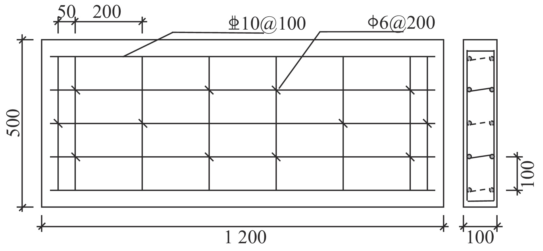
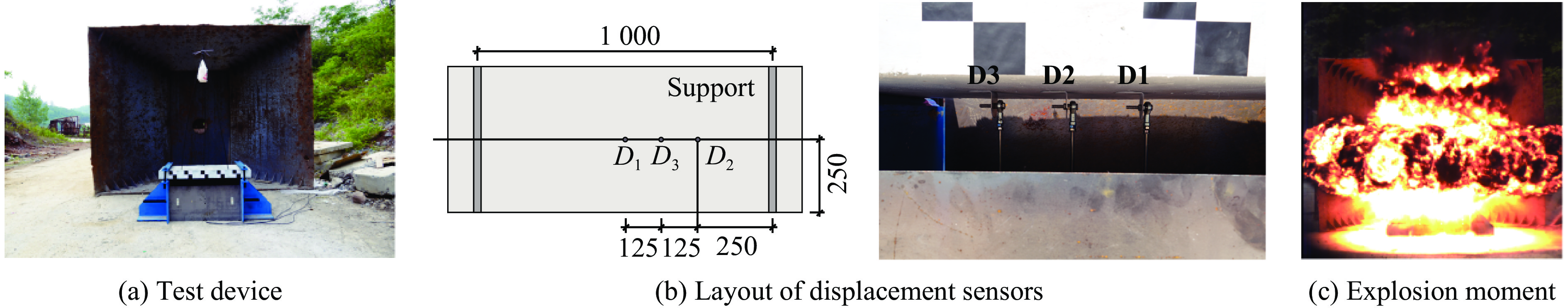
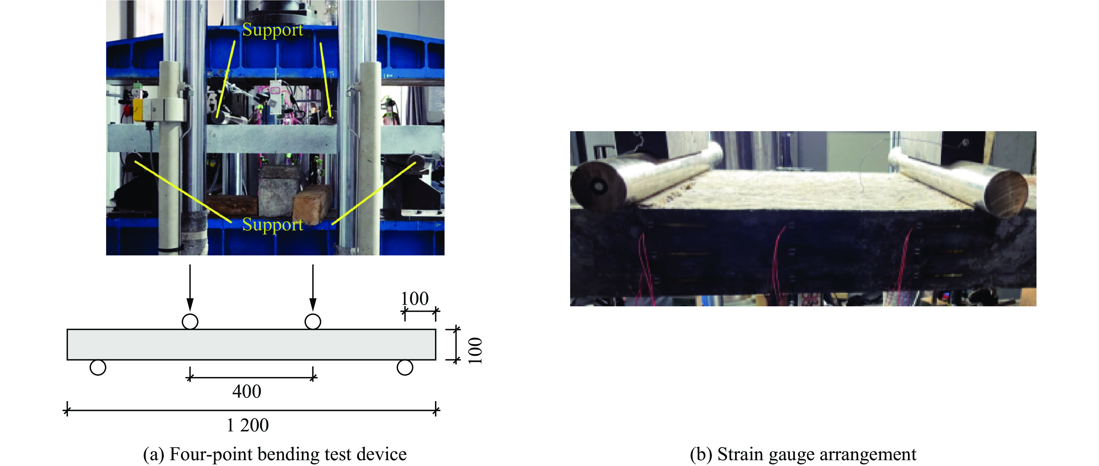
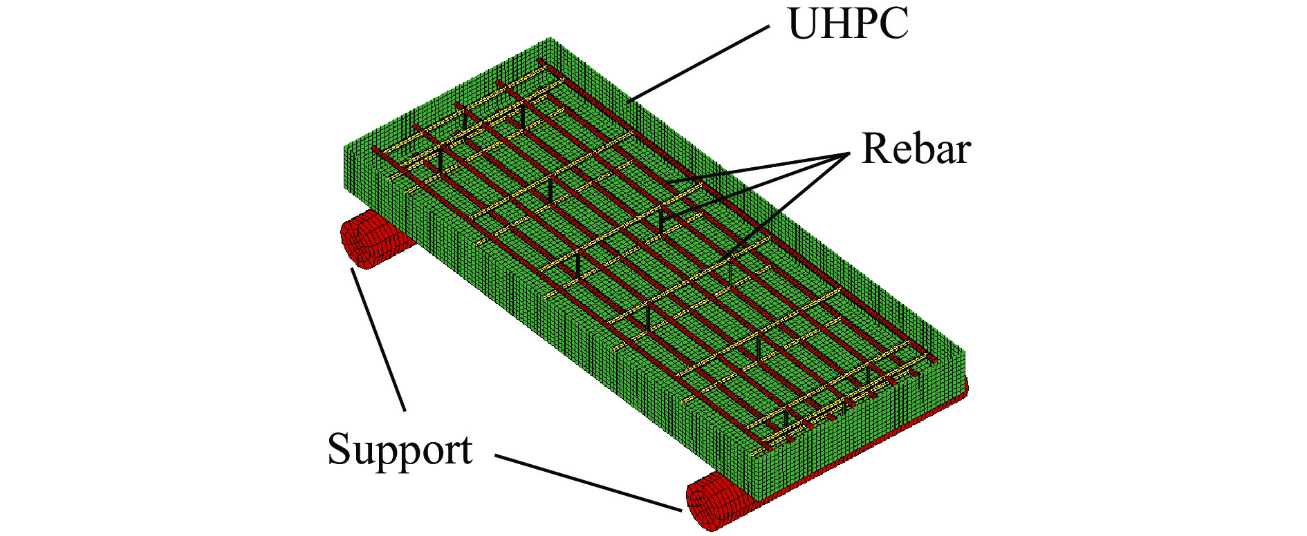
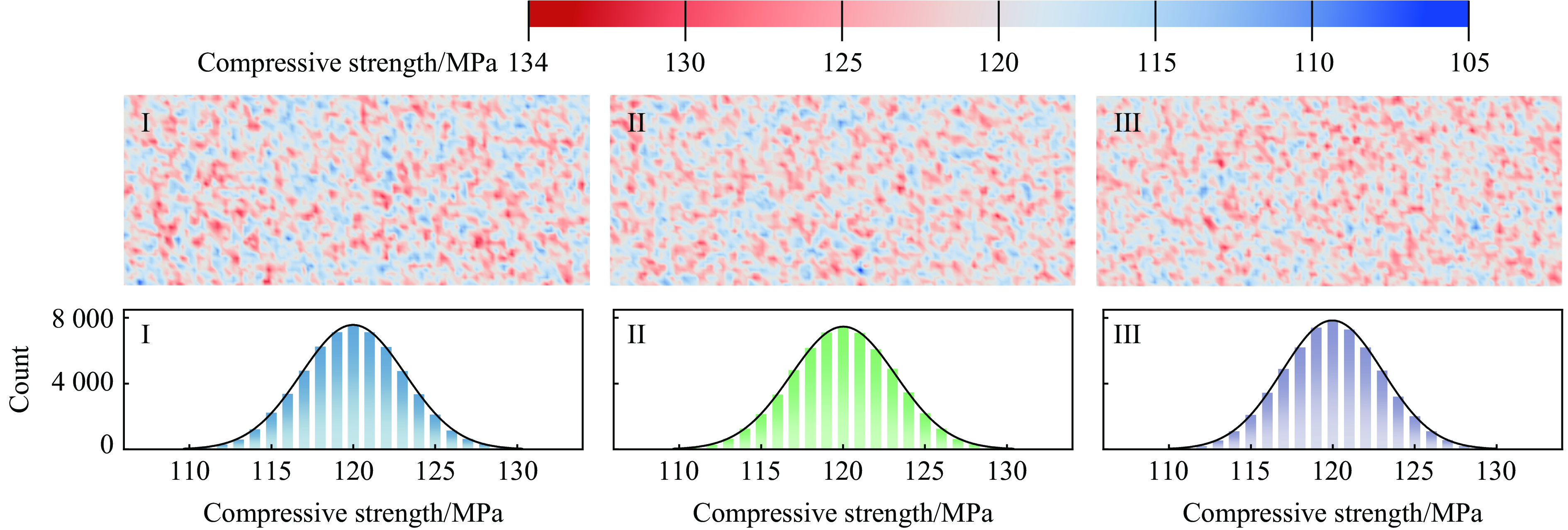
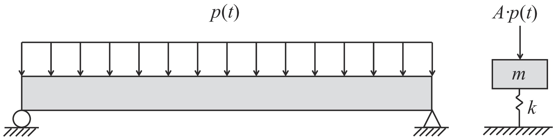
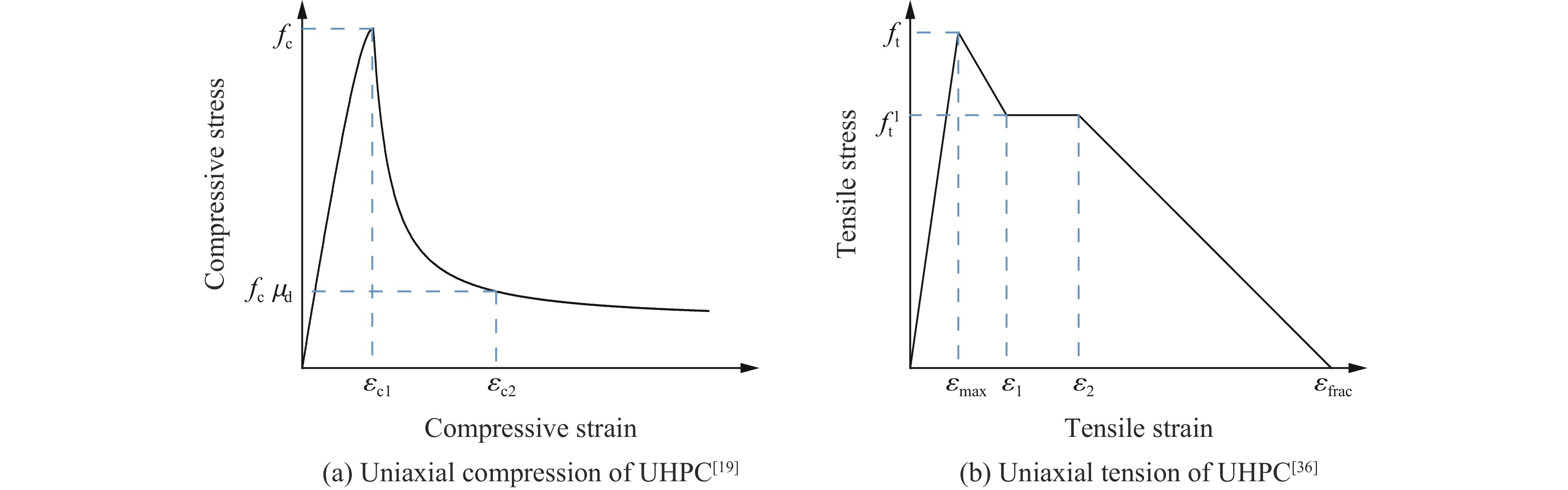
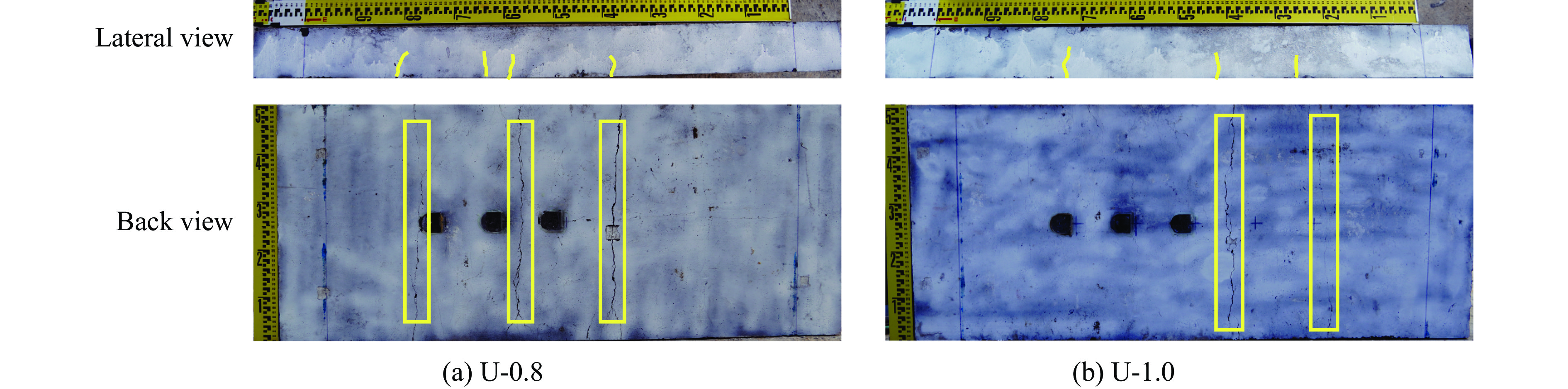
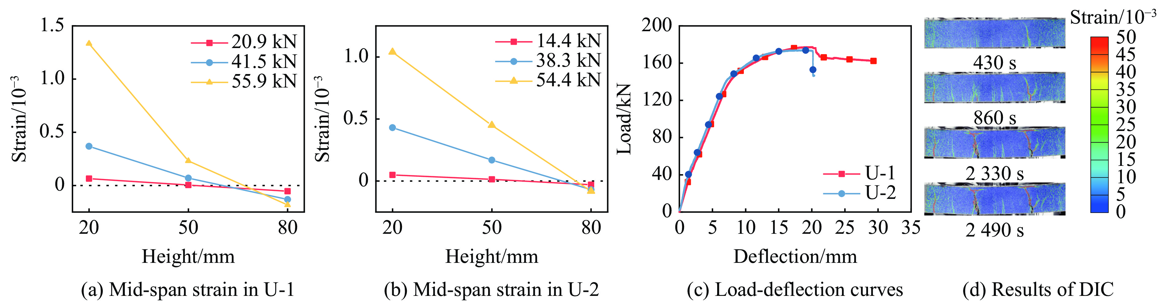
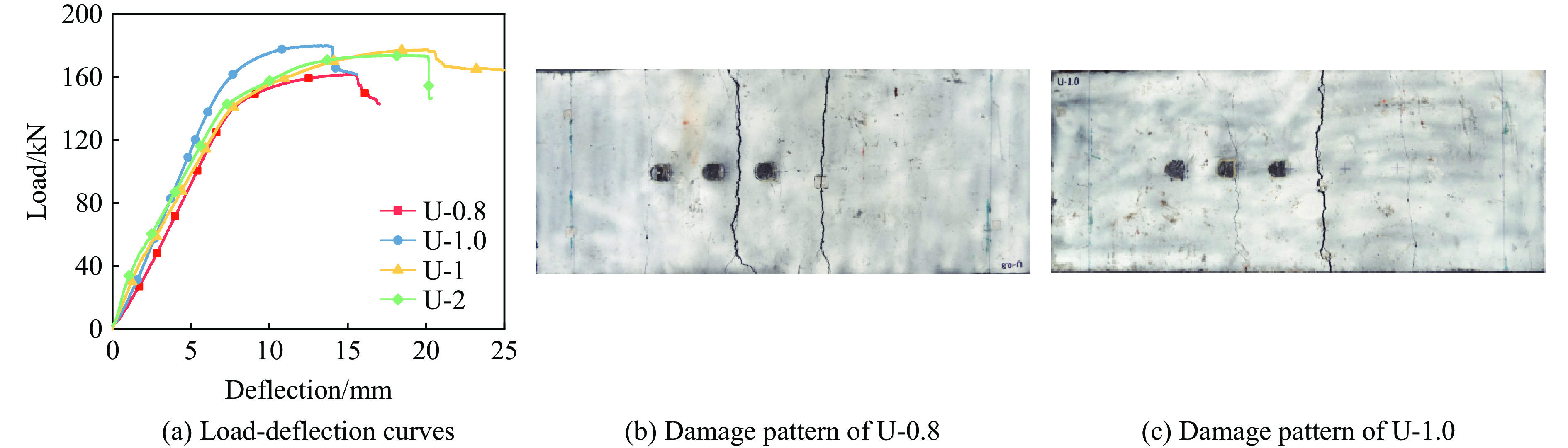
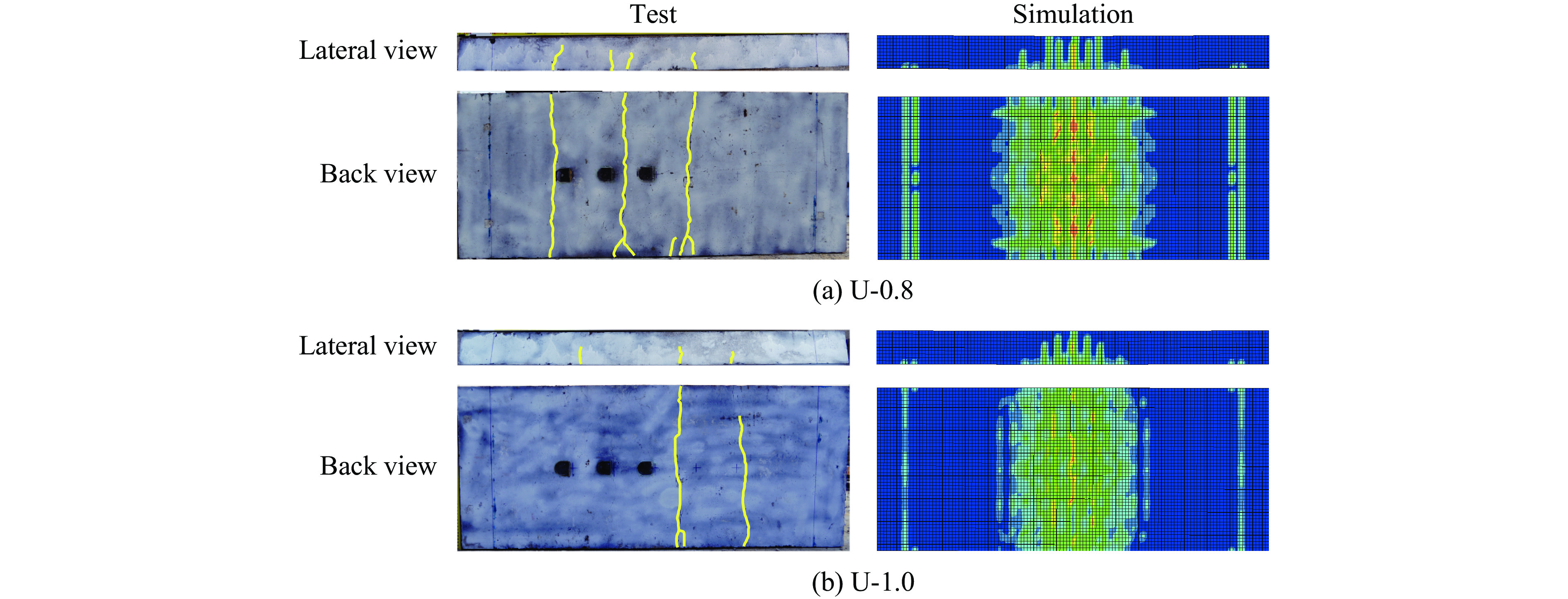
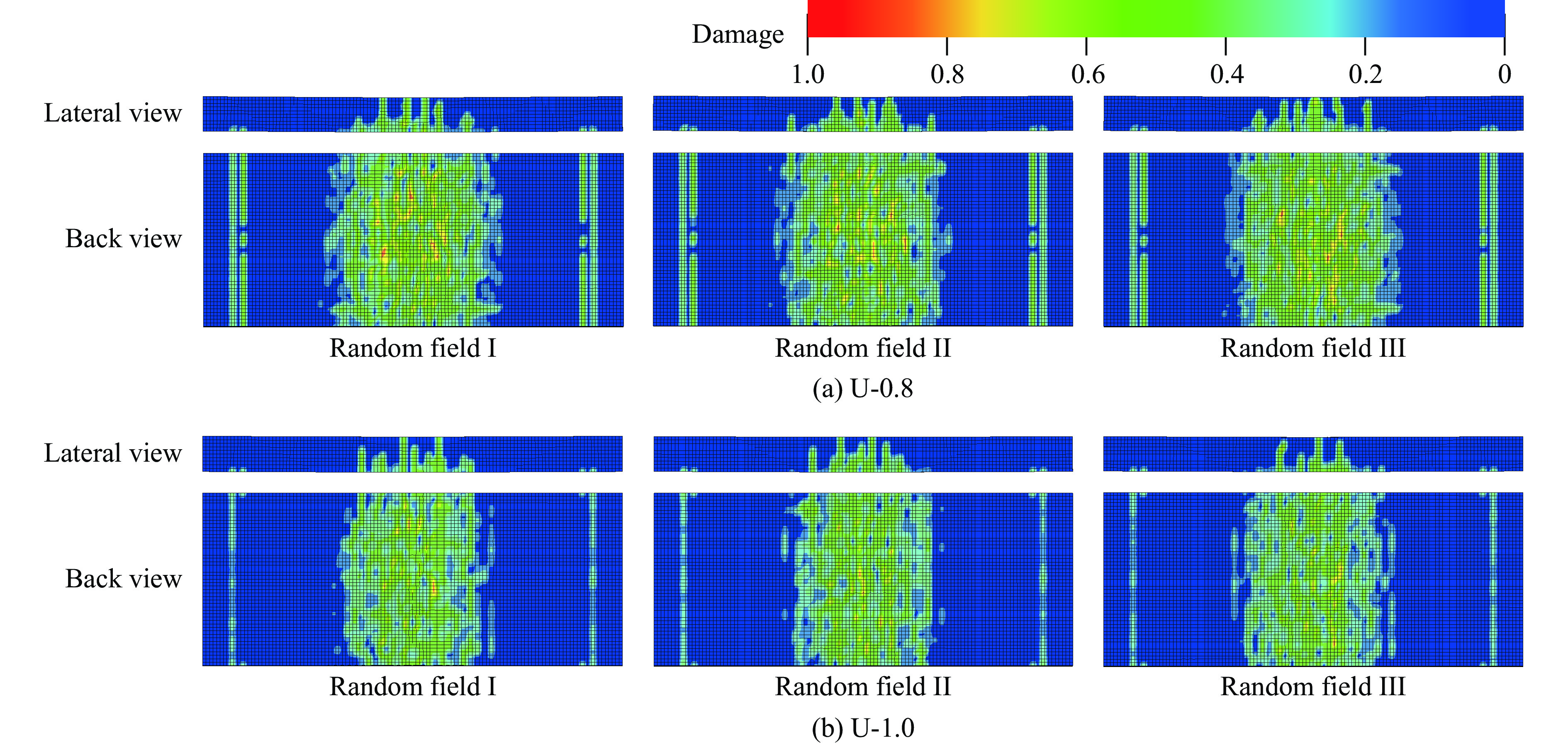
In order to study the blast performance of ultra-high performance concrete (UHPC) panels under intermedium-to-far-field explosion loading, a series of field blast tests were conducted to systematically analyze the influence of scaled blast distances on the failure modes of the specimens. To evaluate the dynamic response of the panels, post-blast and residual strength were investigated through four-point bending tests. To understand the dynamic response mechanism, an equivalent single-degree-of-freedom (SDOF) model was established to predict the mid-span peak deflection under different scaled blast distances. Finite element simulations of the UHPC panels under blast loading were performed using the continuous surface cap (CSC) model to further explore the failure mechanism. Considering uncertainties in material mechanical properties, a stochastic finite element model was developed by introducing a Gaussian autocorrelated spatial random field. The results indicate that UHPC panels maintain structural integrity under intermedium-to-far-field explosion, exhibiting a typical flexural damage mode; damage on the back surface is concentrated in the mid-span region. As the scaled blast distance increased, the extent of damage in the UHPC panels decreased significantly. The deterministic finite element model accurately predicted the blast response of the UHPC panel. The analysis showed that the SDOF method provided accurate predictions of mid-span peak deflection though it tended to overestimate deflection in cases of minor damage where significant plastic deformation did not occur. The random finite element model, by incorporating Gaussian auto-correlated random fields, accounted for the uncertainty in mechanical properties of the material and demonstrated superior simulation results. An increase in the compressive strength of UHPC gradually reduces the mid-span peak deflection, highlighting the effect of material strength on panel deformation. Furthermore, when the auto-correlation length of the random field is within the range of 10 mm to 20 mm, the damage characteristics predicted by the model are highly consistent with the actual observations. This study verifies the excellent blast resistance of UHPC under intermedium-to-far-range explosions, demonstrates the effectiveness of the random finite element model, and reveals the significant influence of material variability on the blast resistance assessment of UHPC structures.
In order to study the blast performance of ultra-high performance concrete (UHPC) panels under intermedium-to-far-field explosion loading, a series of field blast tests were conducted to systematically analyze the influence of scaled blast distances on the failure modes of the specimens. To evaluate the dynamic response of the panels, post-blast and residual strength were investigated through four-point bending tests. To understand the dynamic response mechanism, an equivalent single-degree-of-freedom (SDOF) model was established to predict the mid-span peak deflection under different scaled blast distances. Finite element simulations of the UHPC panels under blast loading were performed using the continuous surface cap (CSC) model to further explore the failure mechanism. Considering uncertainties in material mechanical properties, a stochastic finite element model was developed by introducing a Gaussian autocorrelated spatial random field. The results indicate that UHPC panels maintain structural integrity under intermedium-to-far-field explosion, exhibiting a typical flexural damage mode; damage on the back surface is concentrated in the mid-span region. As the scaled blast distance increased, the extent of damage in the UHPC panels decreased significantly. The deterministic finite element model accurately predicted the blast response of the UHPC panel. The analysis showed that the SDOF method provided accurate predictions of mid-span peak deflection though it tended to overestimate deflection in cases of minor damage where significant plastic deformation did not occur. The random finite element model, by incorporating Gaussian auto-correlated random fields, accounted for the uncertainty in mechanical properties of the material and demonstrated superior simulation results. An increase in the compressive strength of UHPC gradually reduces the mid-span peak deflection, highlighting the effect of material strength on panel deformation. Furthermore, when the auto-correlation length of the random field is within the range of 10 mm to 20 mm, the damage characteristics predicted by the model are highly consistent with the actual observations. This study verifies the excellent blast resistance of UHPC under intermedium-to-far-range explosions, demonstrates the effectiveness of the random finite element model, and reveals the significant influence of material variability on the blast resistance assessment of UHPC structures.


, Available online , doi: 10.11883/bzycj-2025-0227
Abstract:
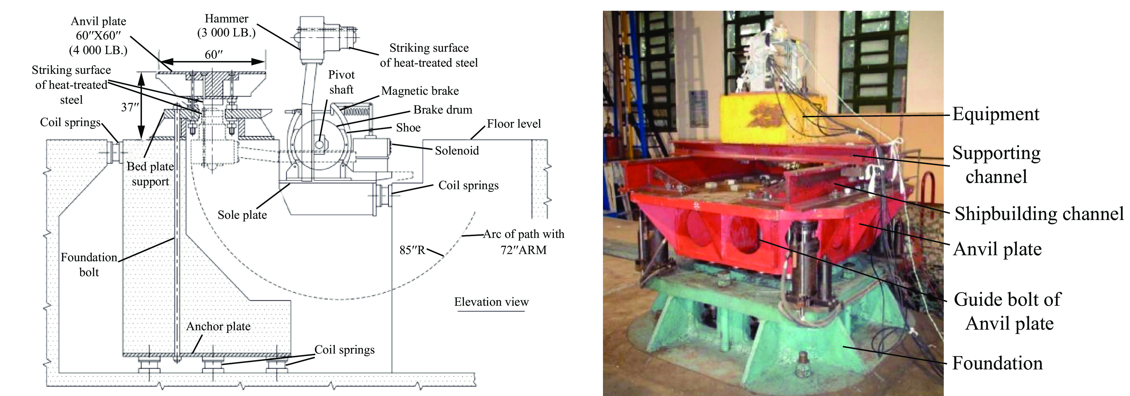
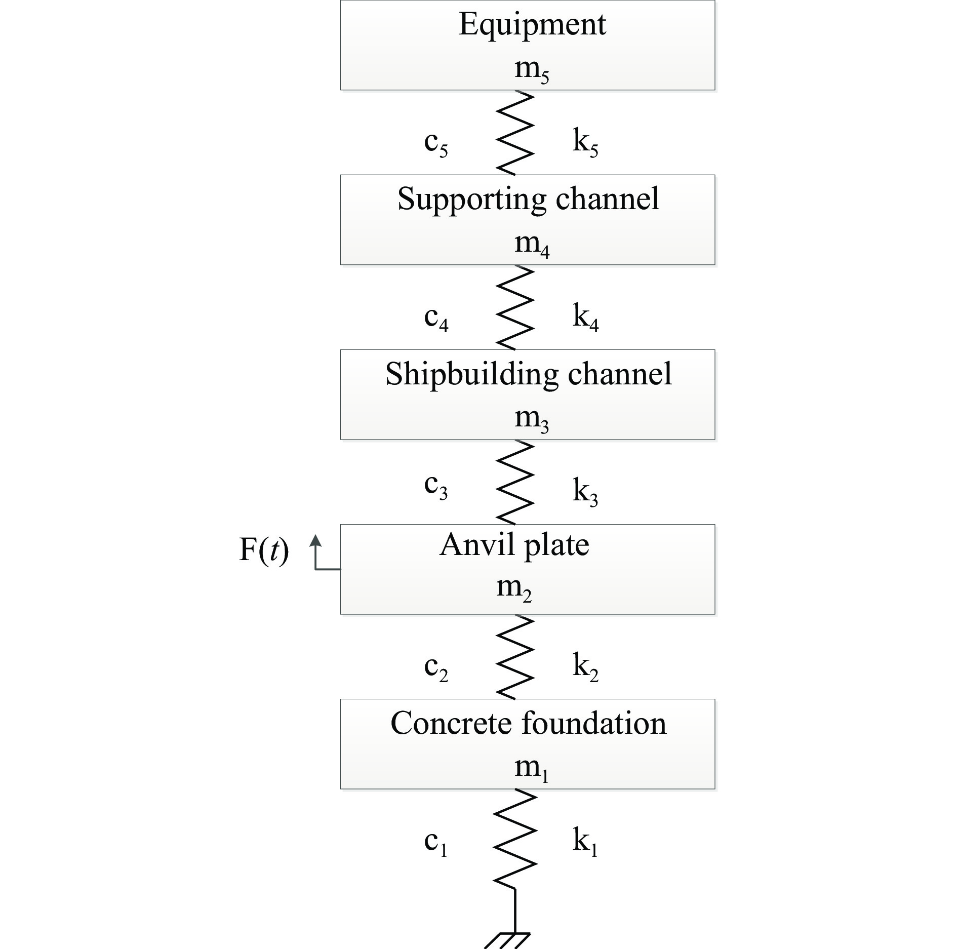
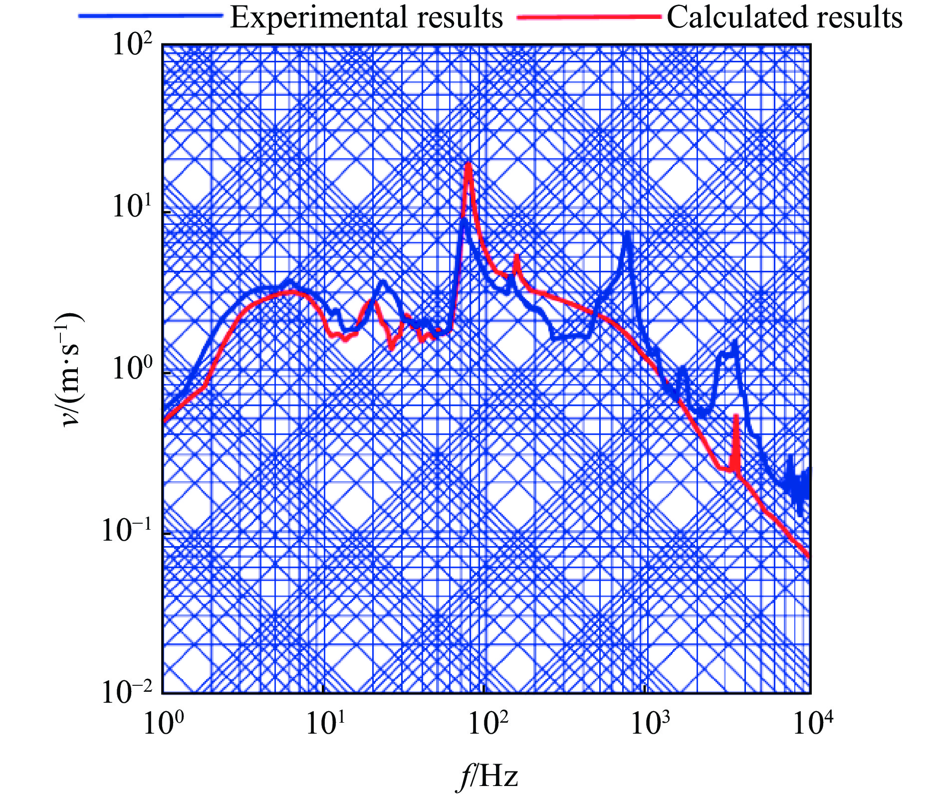
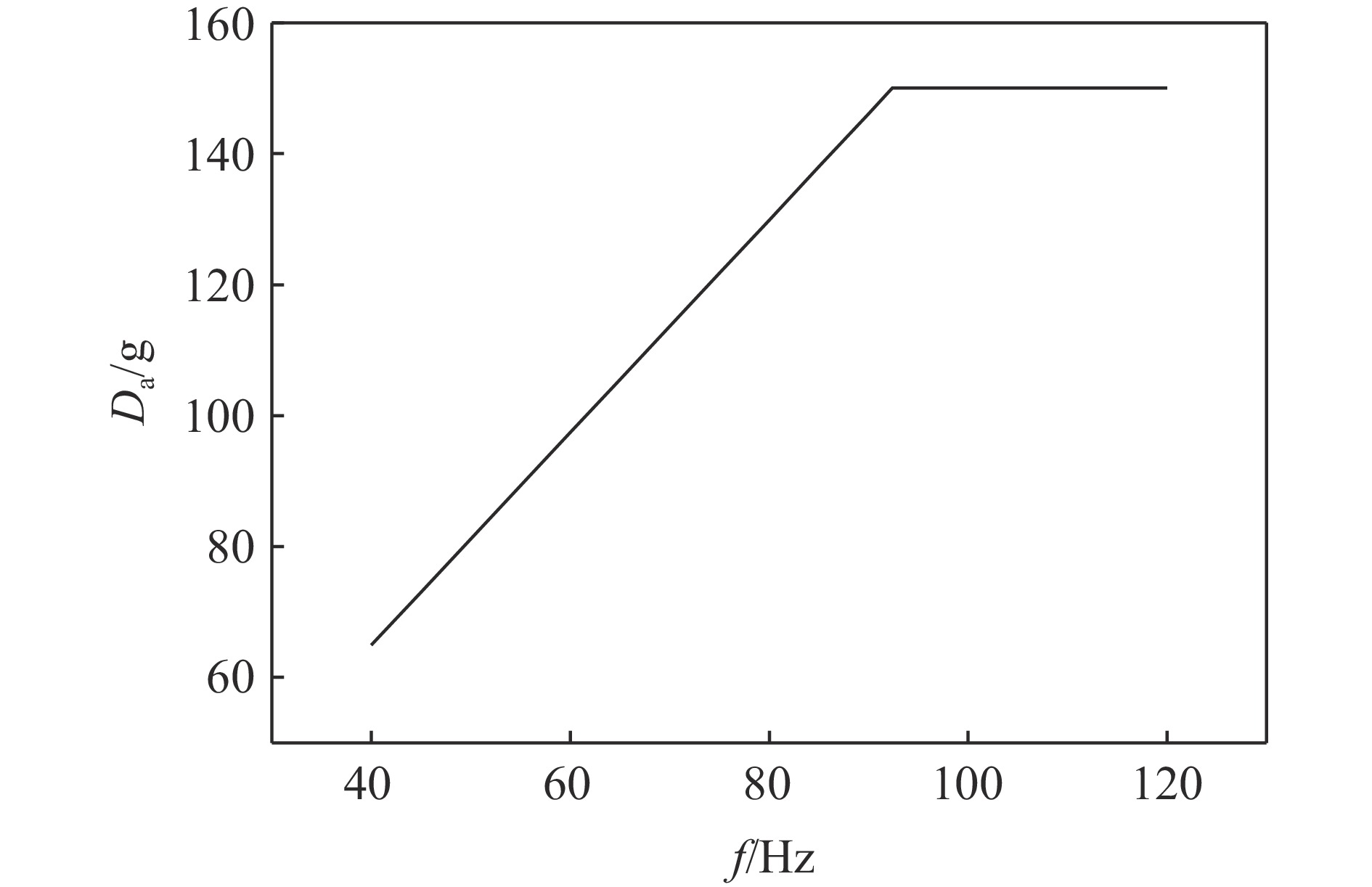
At present, there is a lack of research on the correlation between the shock design load specified in GJB1060.1-1991 and the shock test load corresponding to the test conditions specified in GJB150.18-1986 in China. Without a clear understanding of the severities of shock design loads and shock test loads, it is impossible to accurately guide the anti-shock design for the evaluation and testing of ship equipment. Taking the medium-weight shock test specified in GJB150.18-1986 standard as a case, a multi-degree-of-freedom mass stiffness damping dynamic model is established. Considering the single-degree-of-freedom rigid installation equipment installed on the hull (the equipment itself is assumed to be rigid), the shock test load calculation under the standard conditions can be carried out. It can be found that there are upper and lower limits for the shock spectrum velocity of the test load anvil where the lower limit is about 1.75 m/s and the upper limit is about 2.40 m/s. A calculation formula of the shock test spectrum velocity is fitted. Based on the DDAM (dynamic design analysis method) method and the shock design spectrum value specified in GJB1060.1-1991, the shock design spectrum velocity calculated is compared with the shock test load, and the influences of equipment installation frequency, equipment mass and pendulum height on the shock design load and shock test load are analyzed. Based on the comparison results, it is found that the shock design load is more severe than the shock test load. However, when the channel steel span is relatively large (greater than 90 cm) and the equipment installation frequency is relatively high (greater than 80 Hz), the shock test load may be more severe. In addition, the quantitative ratio between the velocity of the shock design spectrum and that of the shock test spectrum is provided. The research results prove the correlation between the shock design load and the shock test load, which can provide reference for the shock resistance design and shock test of the equipment and the revision of relevant standards.
At present, there is a lack of research on the correlation between the shock design load specified in GJB1060.1-1991 and the shock test load corresponding to the test conditions specified in GJB150.18-1986 in China. Without a clear understanding of the severities of shock design loads and shock test loads, it is impossible to accurately guide the anti-shock design for the evaluation and testing of ship equipment. Taking the medium-weight shock test specified in GJB150.18-1986 standard as a case, a multi-degree-of-freedom mass stiffness damping dynamic model is established. Considering the single-degree-of-freedom rigid installation equipment installed on the hull (the equipment itself is assumed to be rigid), the shock test load calculation under the standard conditions can be carried out. It can be found that there are upper and lower limits for the shock spectrum velocity of the test load anvil where the lower limit is about 1.75 m/s and the upper limit is about 2.40 m/s. A calculation formula of the shock test spectrum velocity is fitted. Based on the DDAM (dynamic design analysis method) method and the shock design spectrum value specified in GJB1060.1-1991, the shock design spectrum velocity calculated is compared with the shock test load, and the influences of equipment installation frequency, equipment mass and pendulum height on the shock design load and shock test load are analyzed. Based on the comparison results, it is found that the shock design load is more severe than the shock test load. However, when the channel steel span is relatively large (greater than 90 cm) and the equipment installation frequency is relatively high (greater than 80 Hz), the shock test load may be more severe. In addition, the quantitative ratio between the velocity of the shock design spectrum and that of the shock test spectrum is provided. The research results prove the correlation between the shock design load and the shock test load, which can provide reference for the shock resistance design and shock test of the equipment and the revision of relevant standards.
, Available online , doi: 10.11883/bzycj-2025-0295
Abstract:
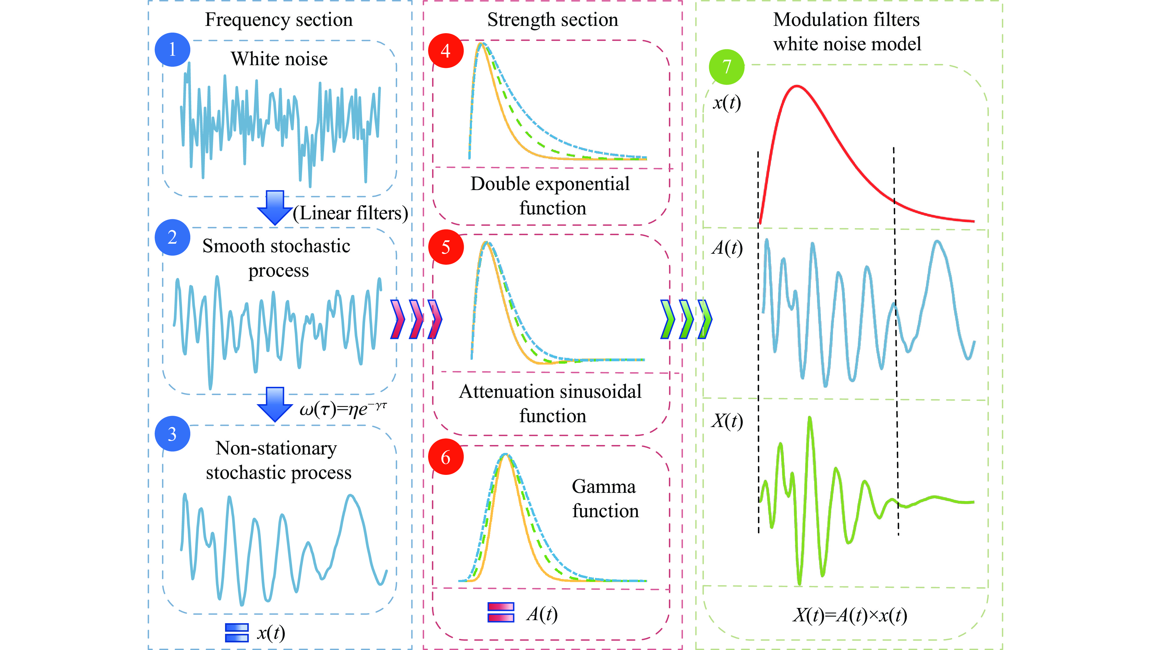
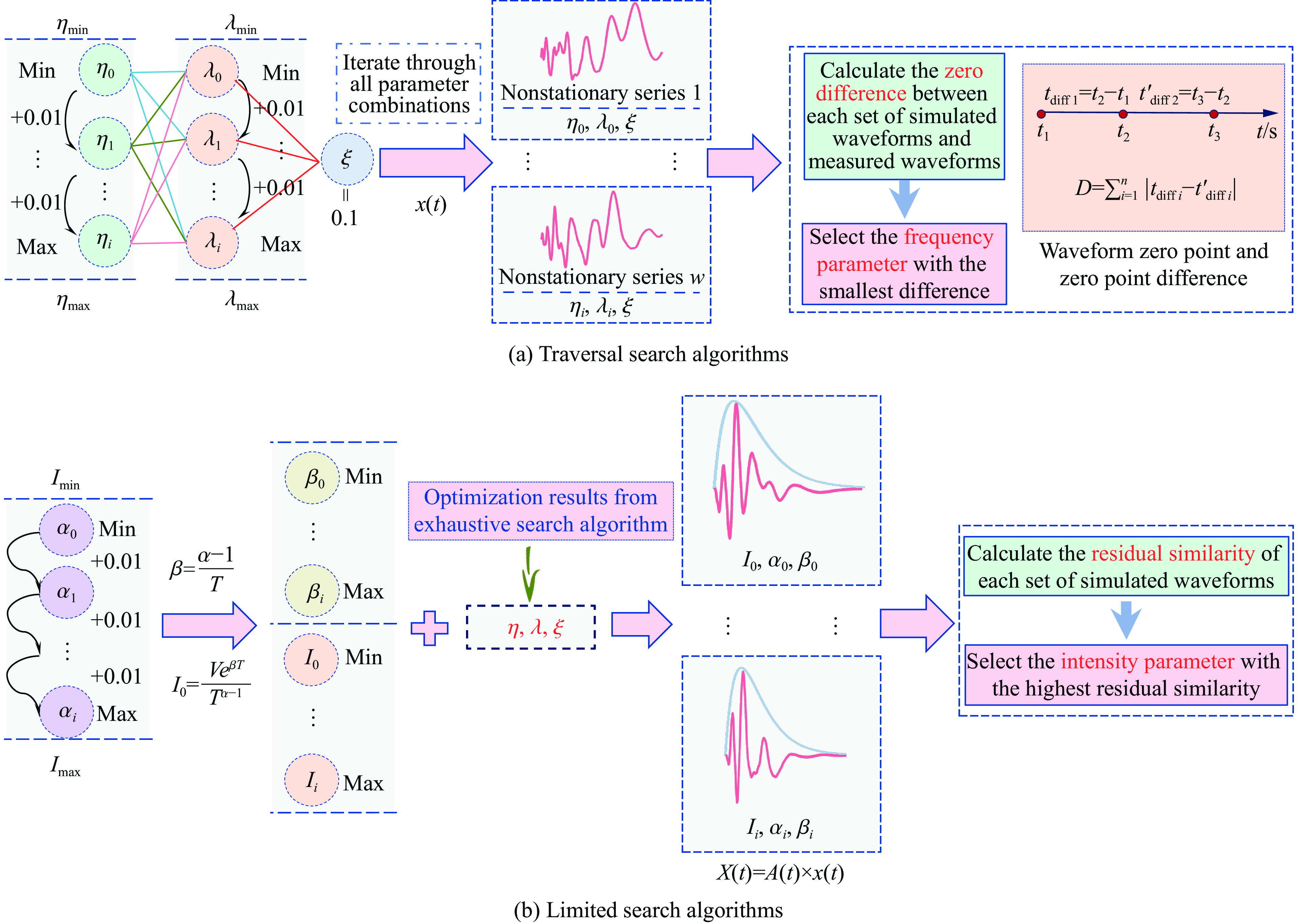
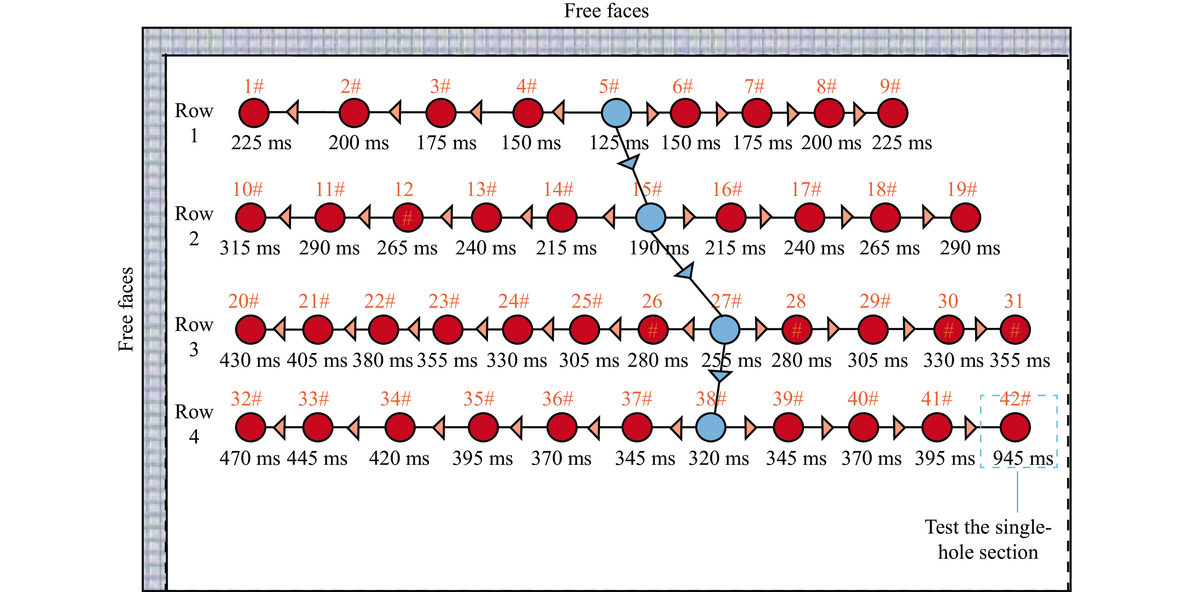
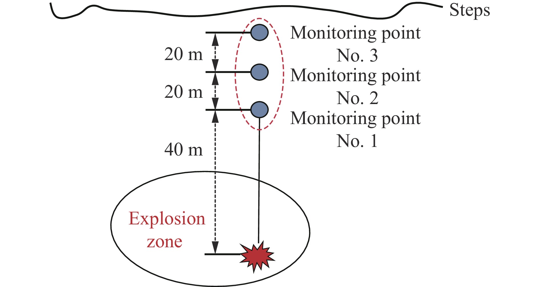
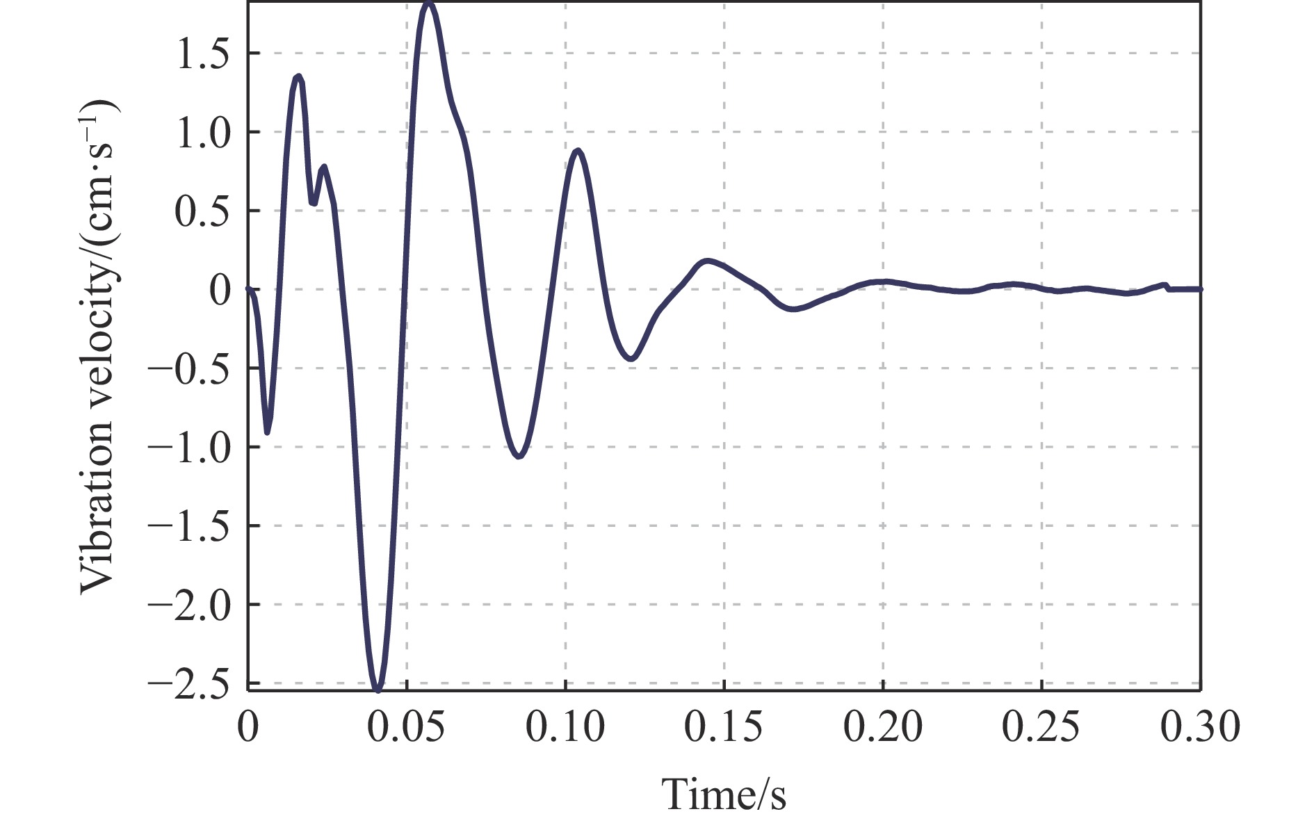
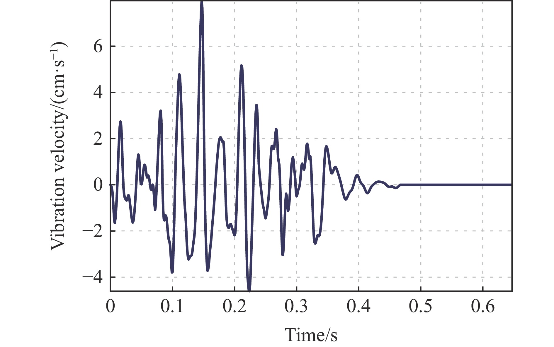
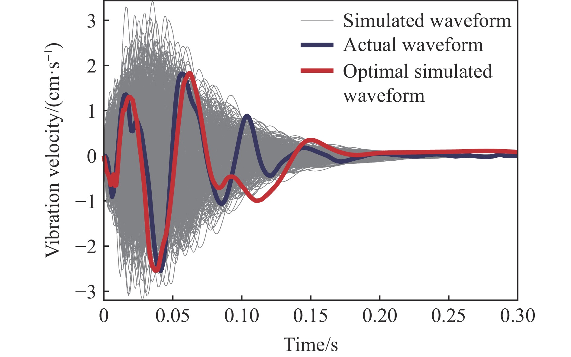
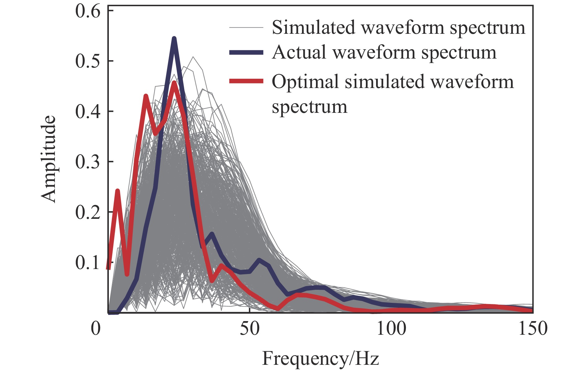
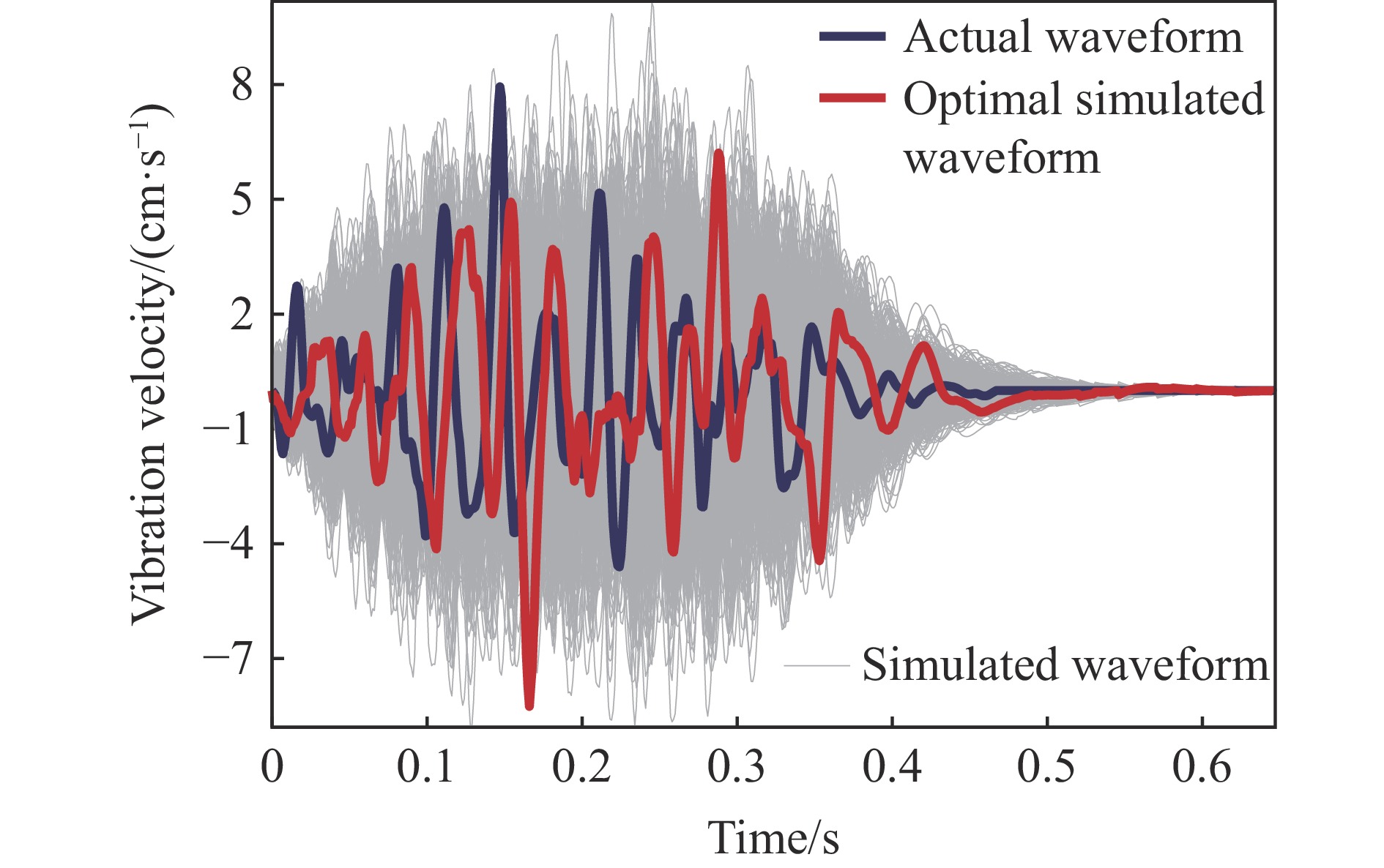
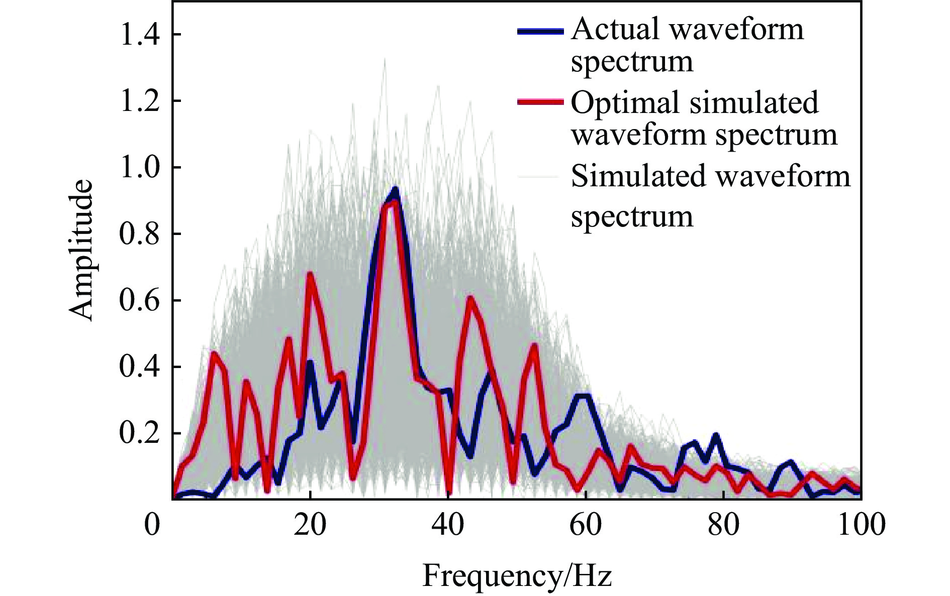
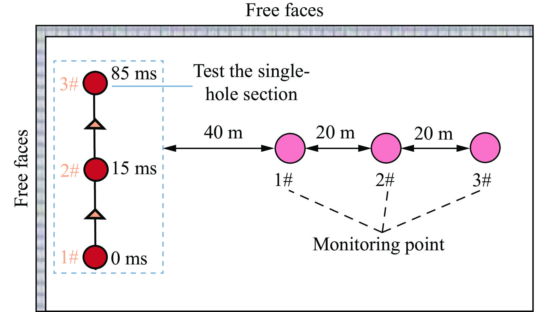
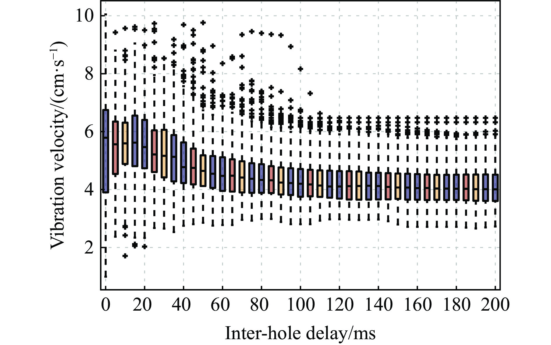
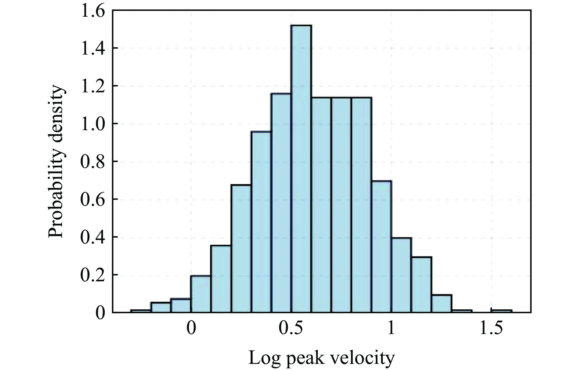
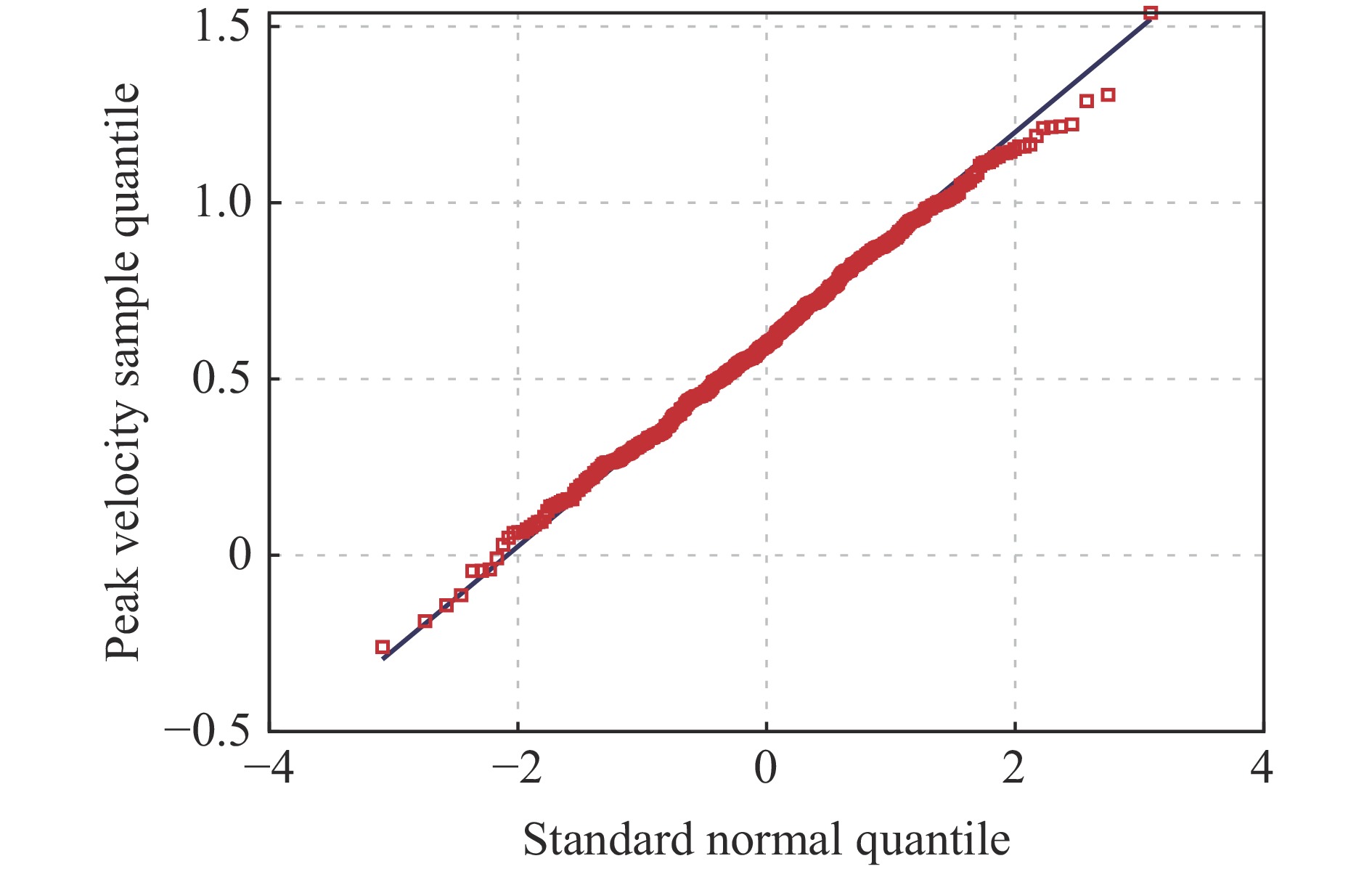
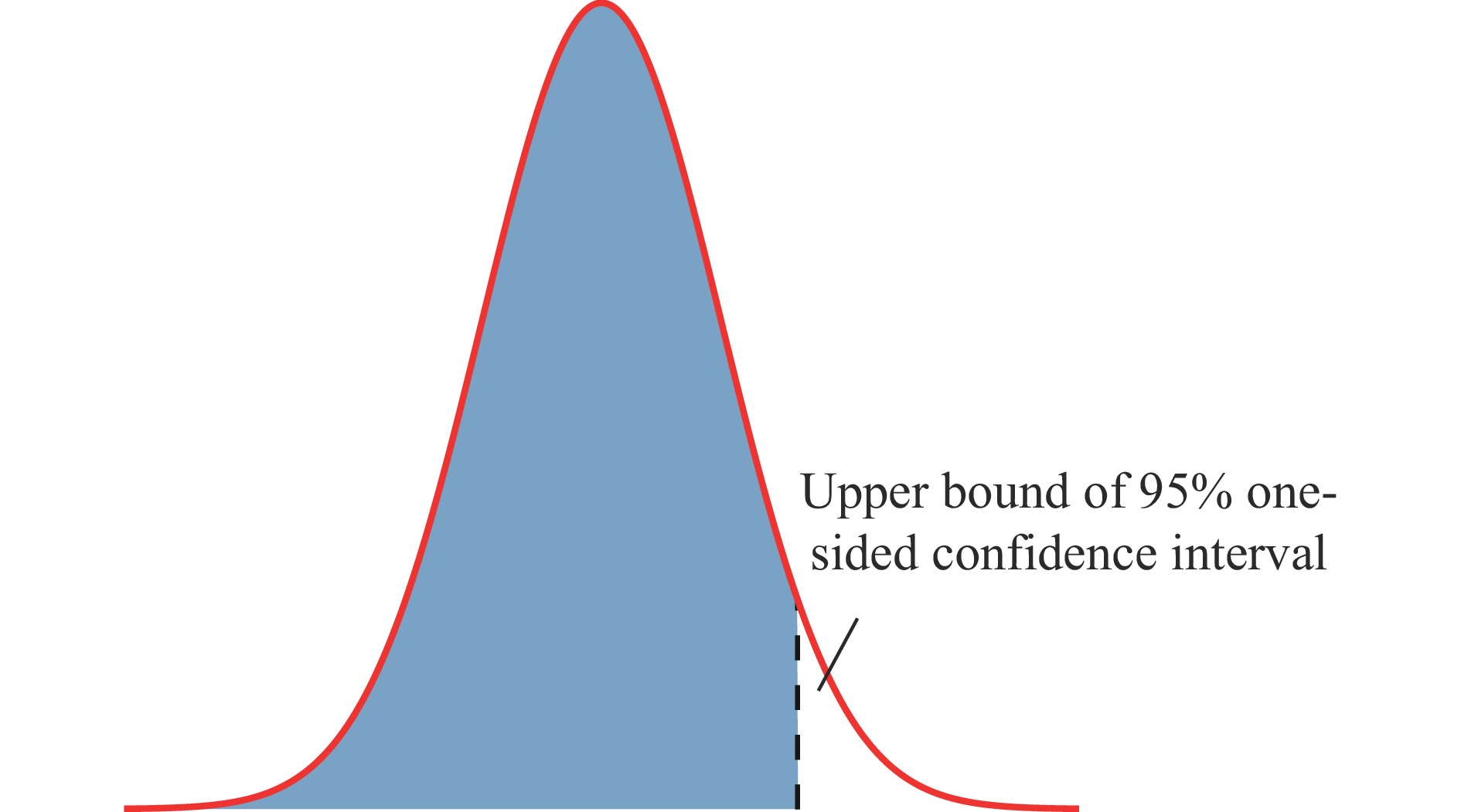
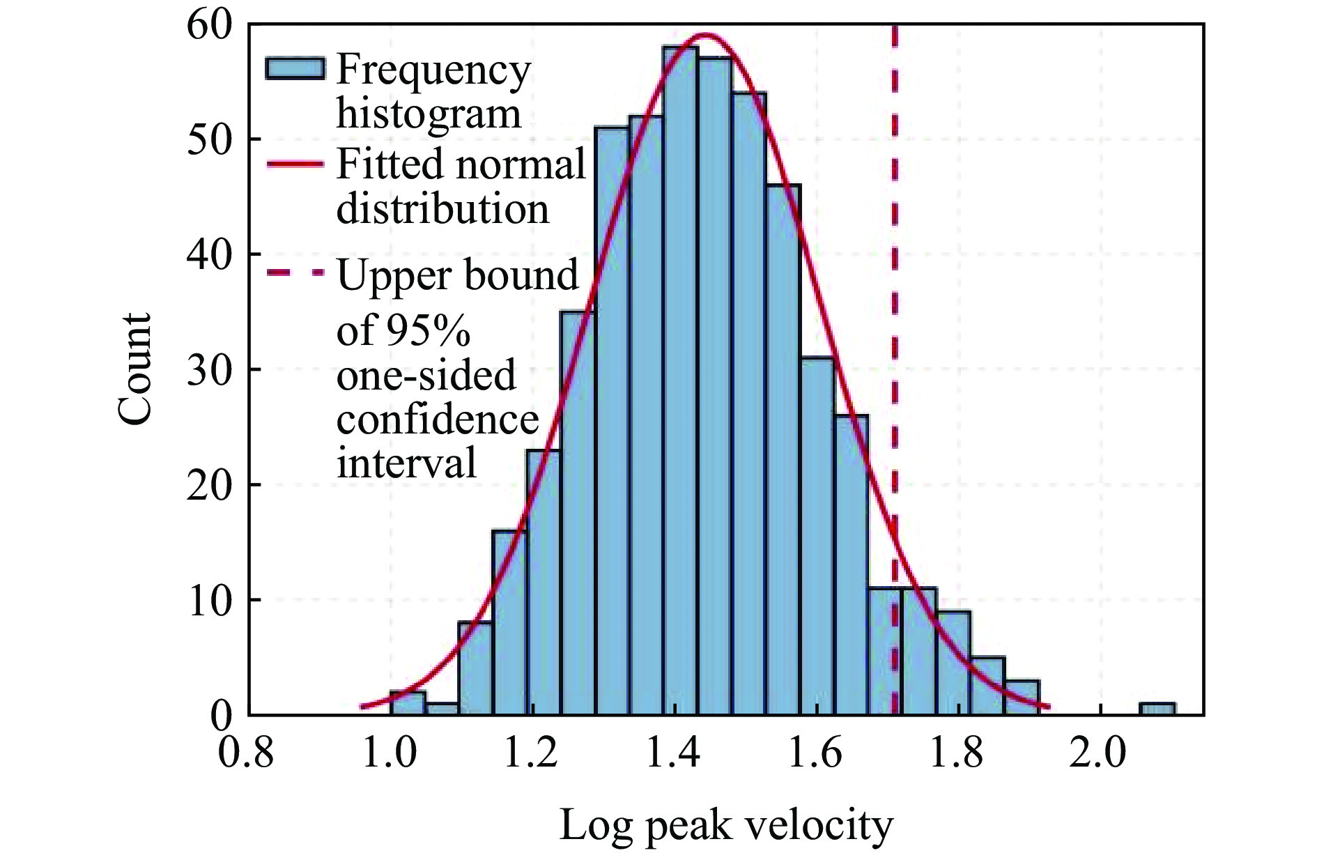
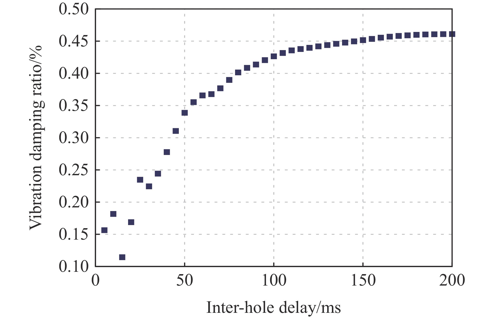
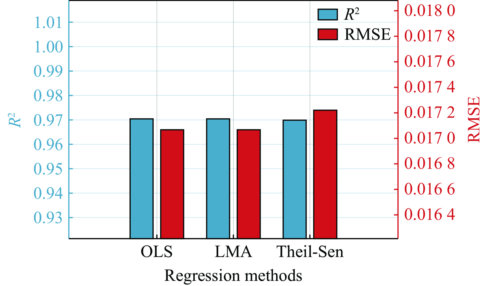
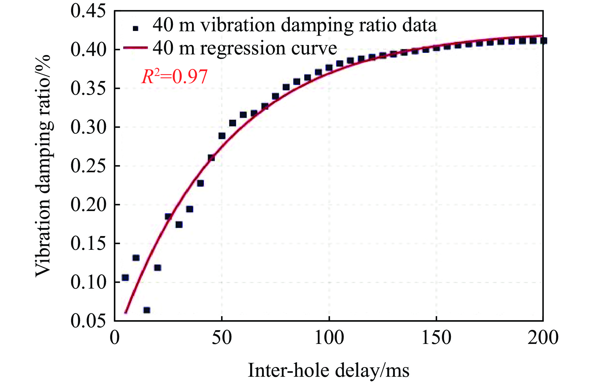
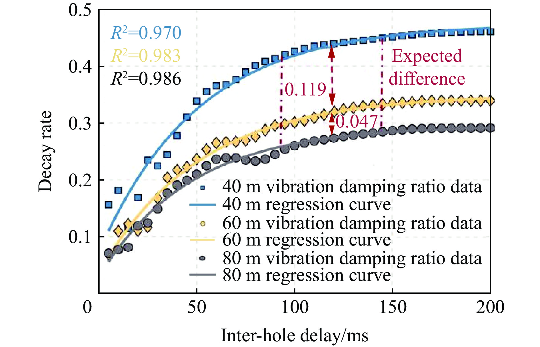
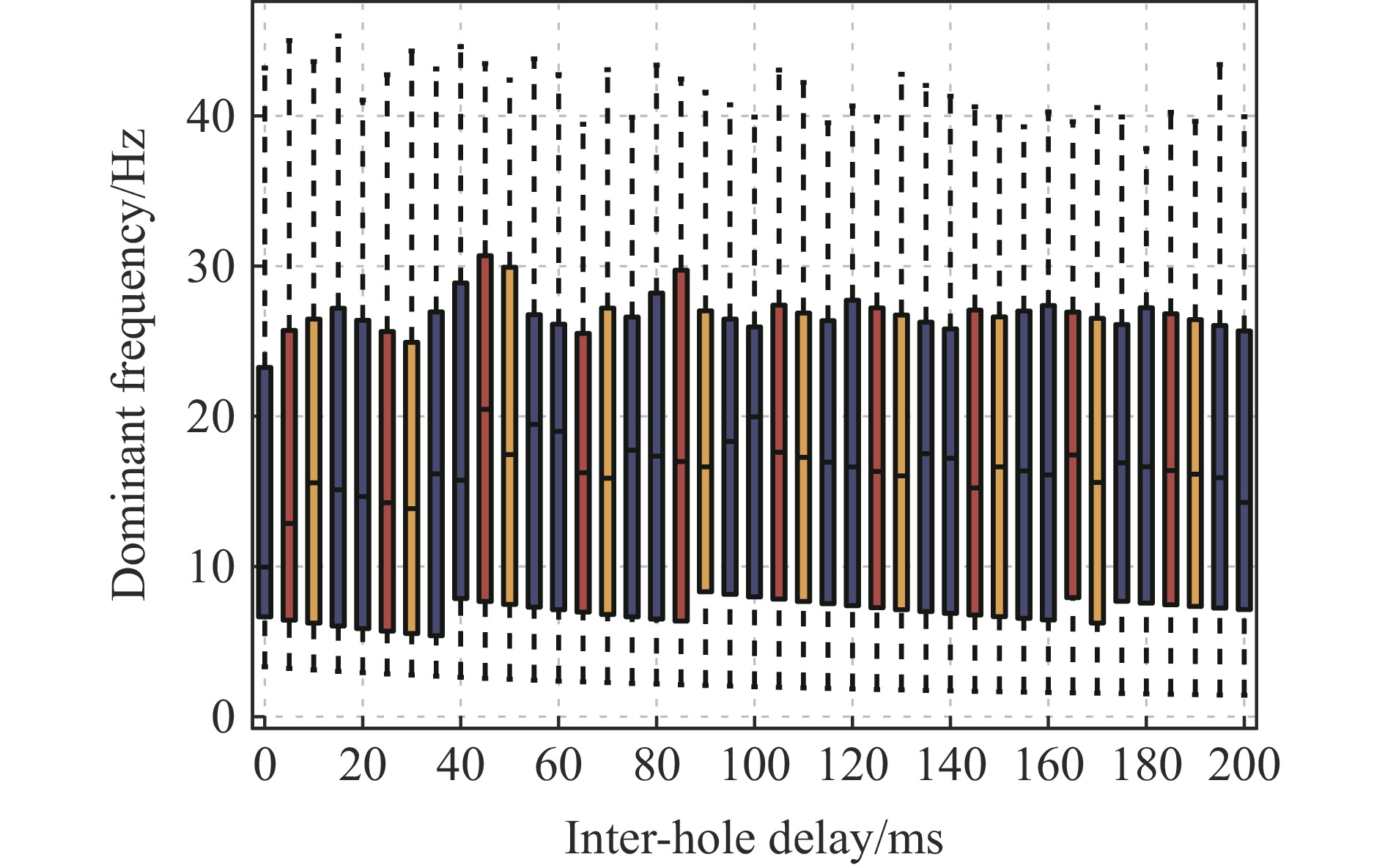
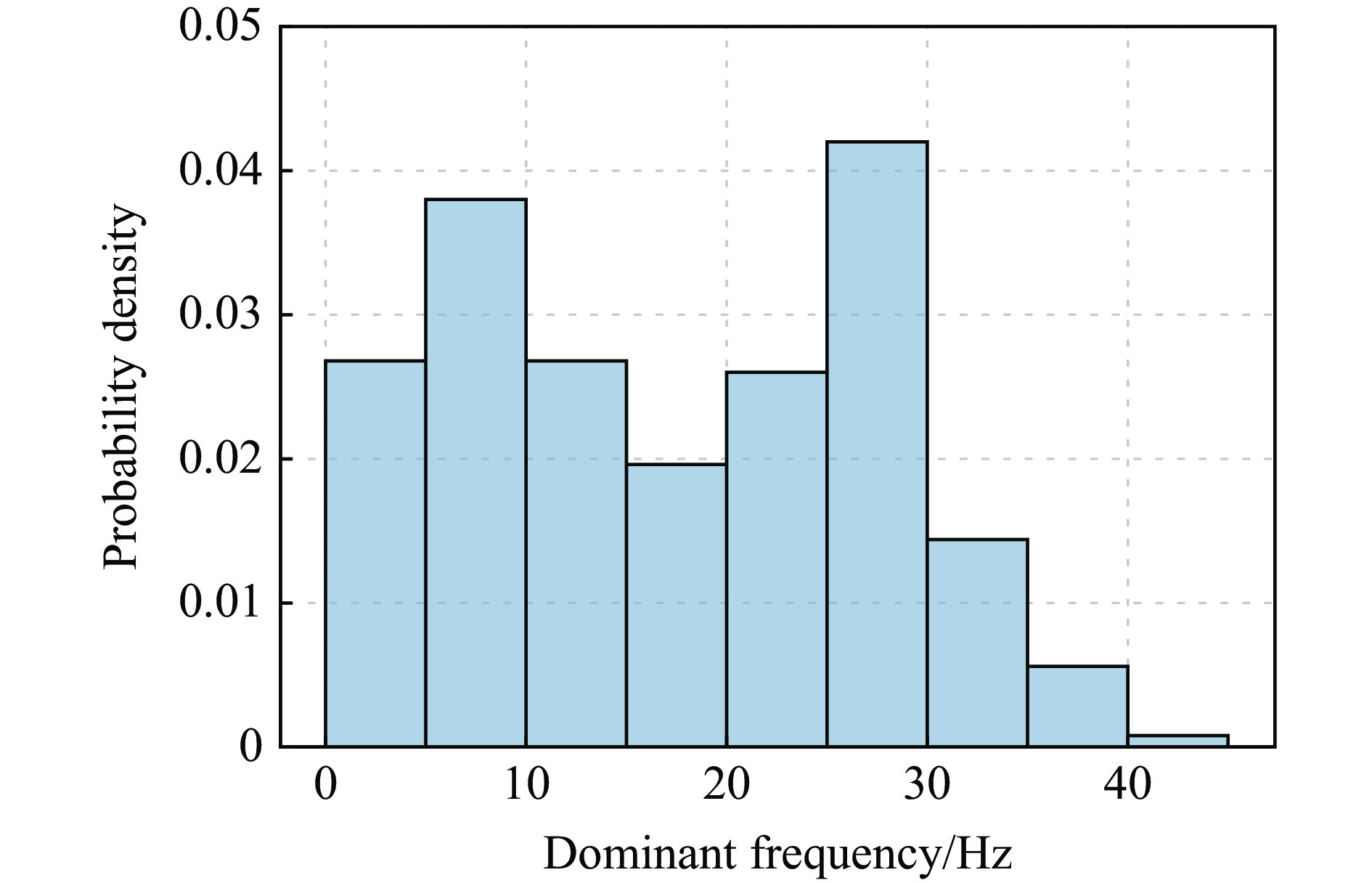
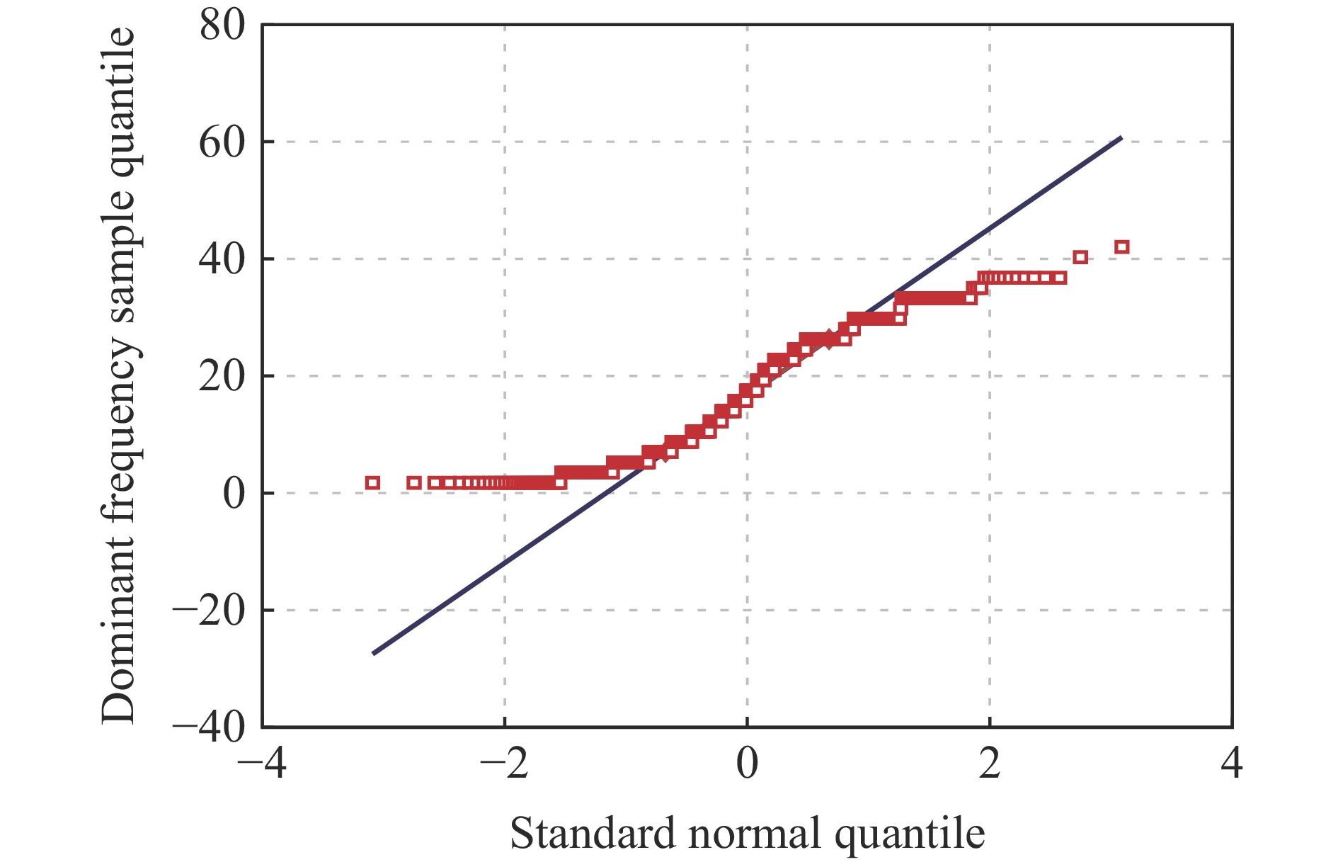
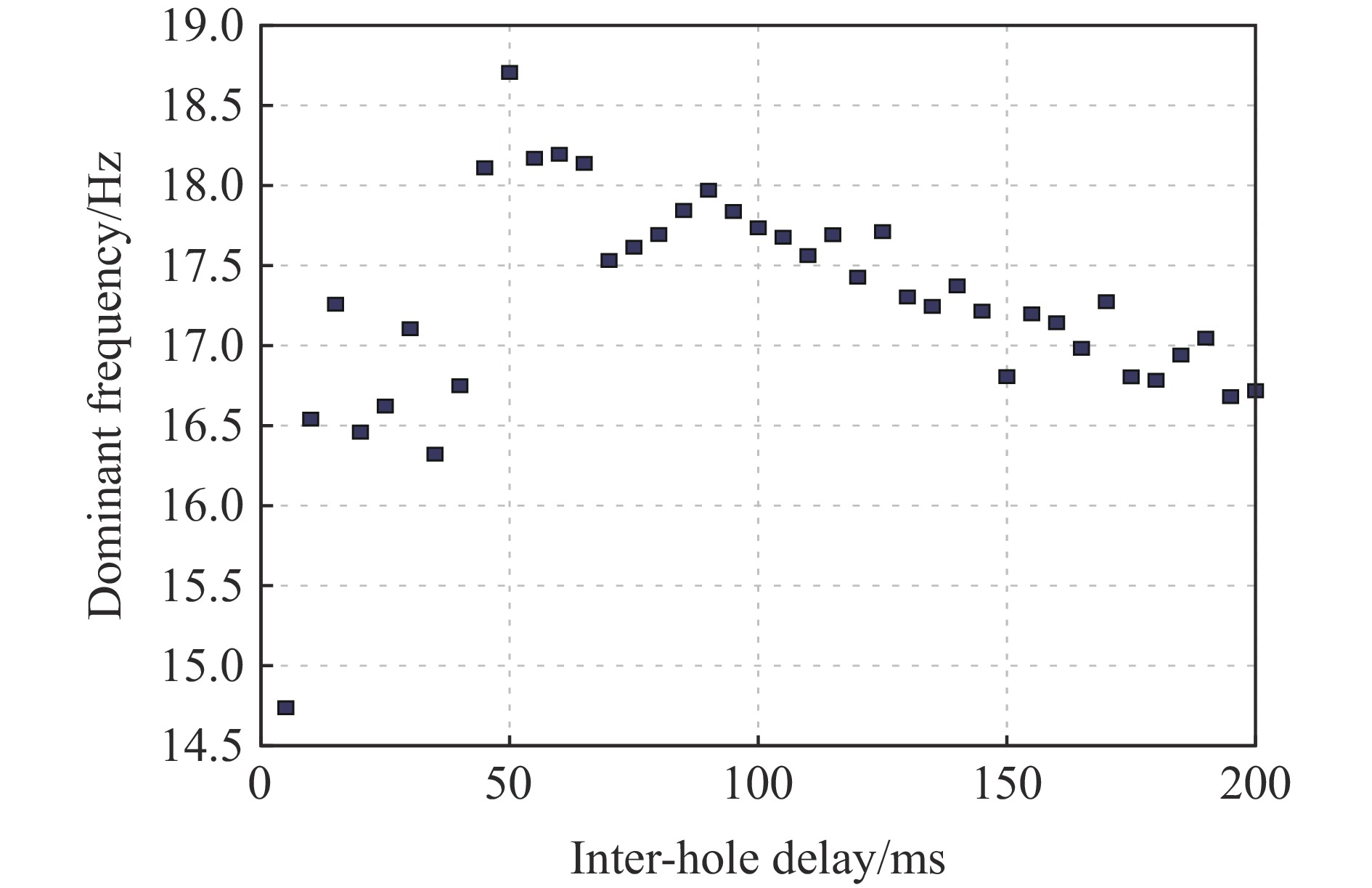
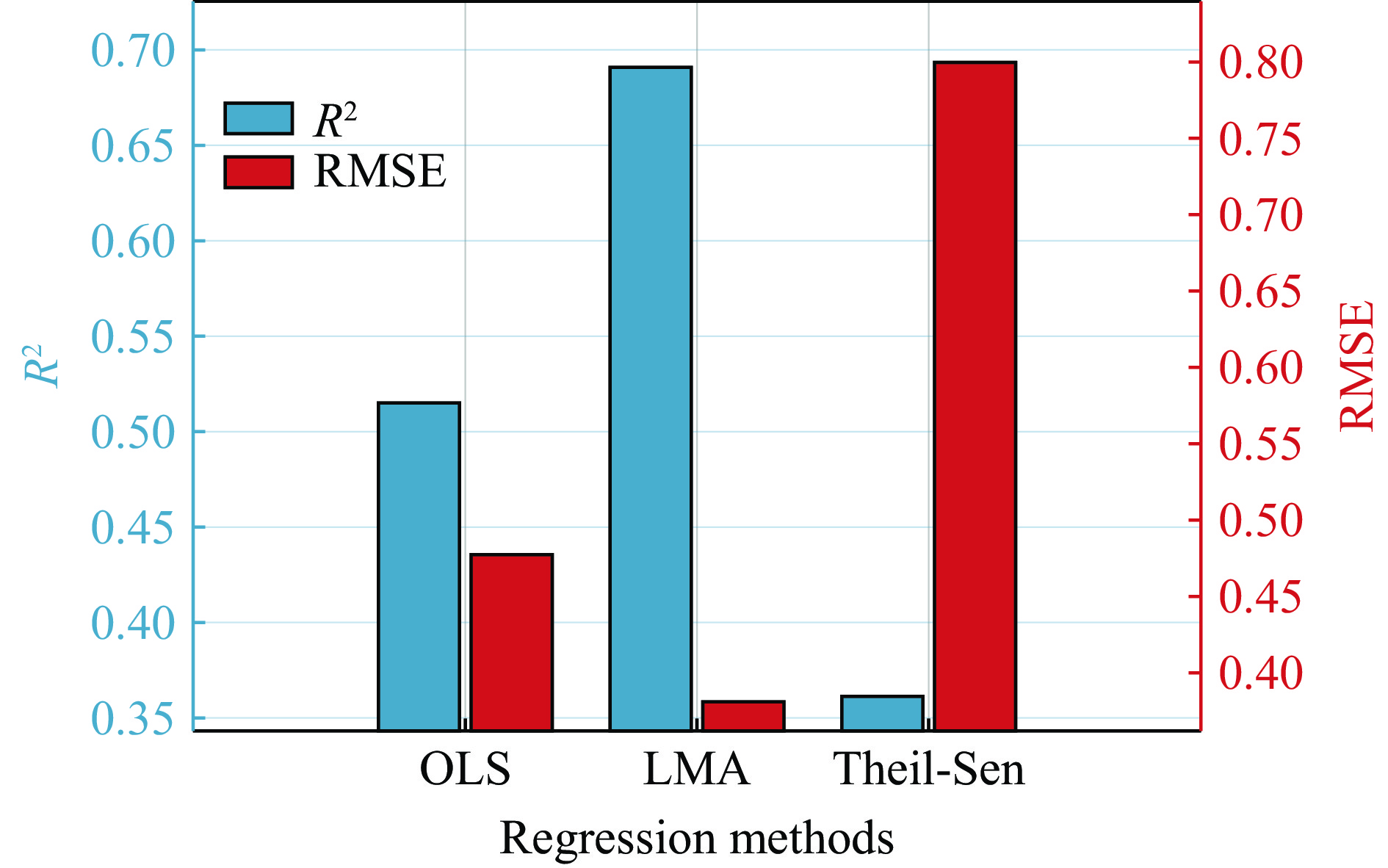
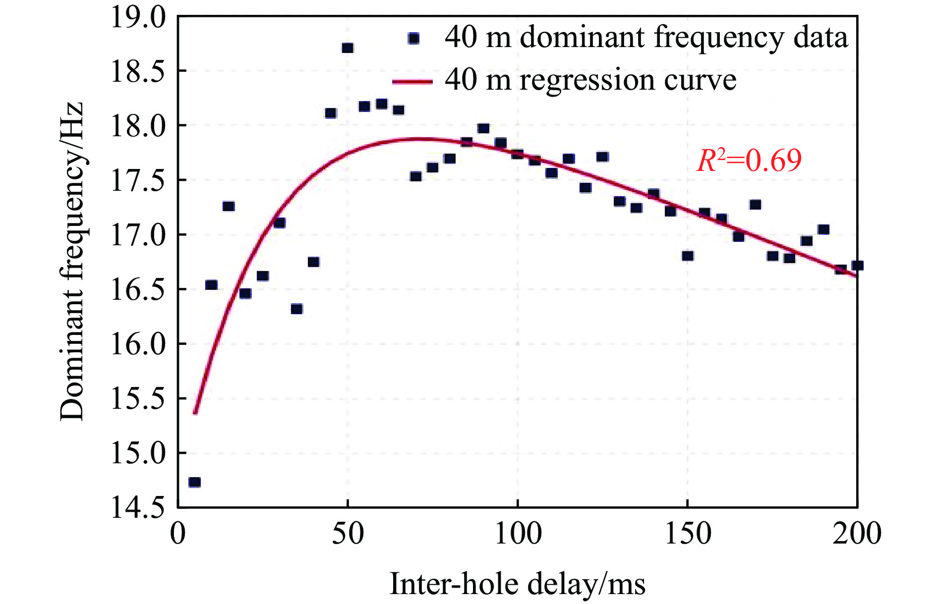
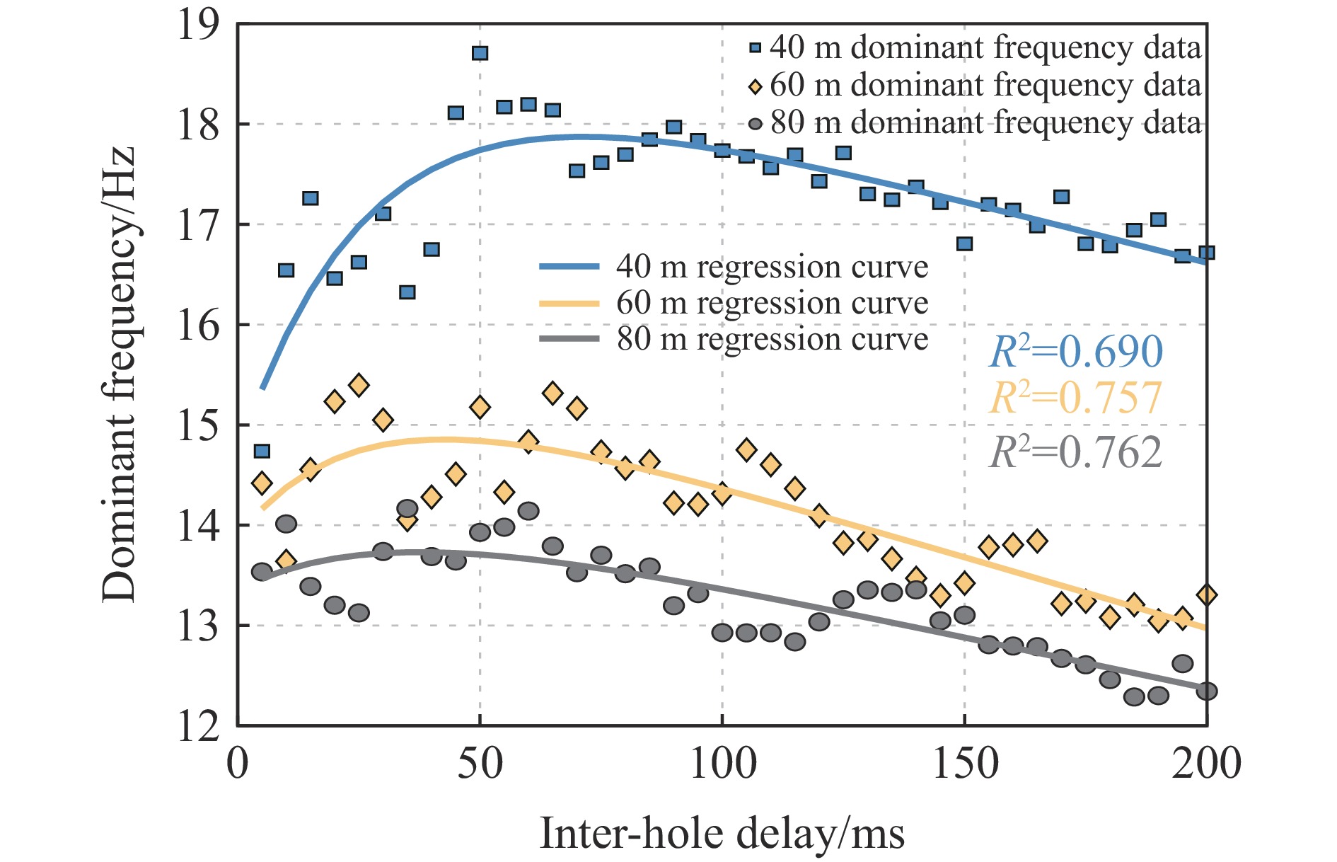
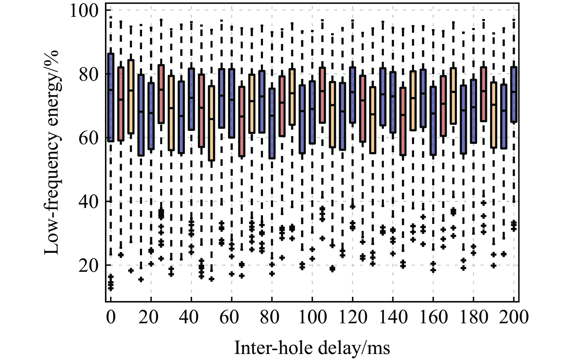
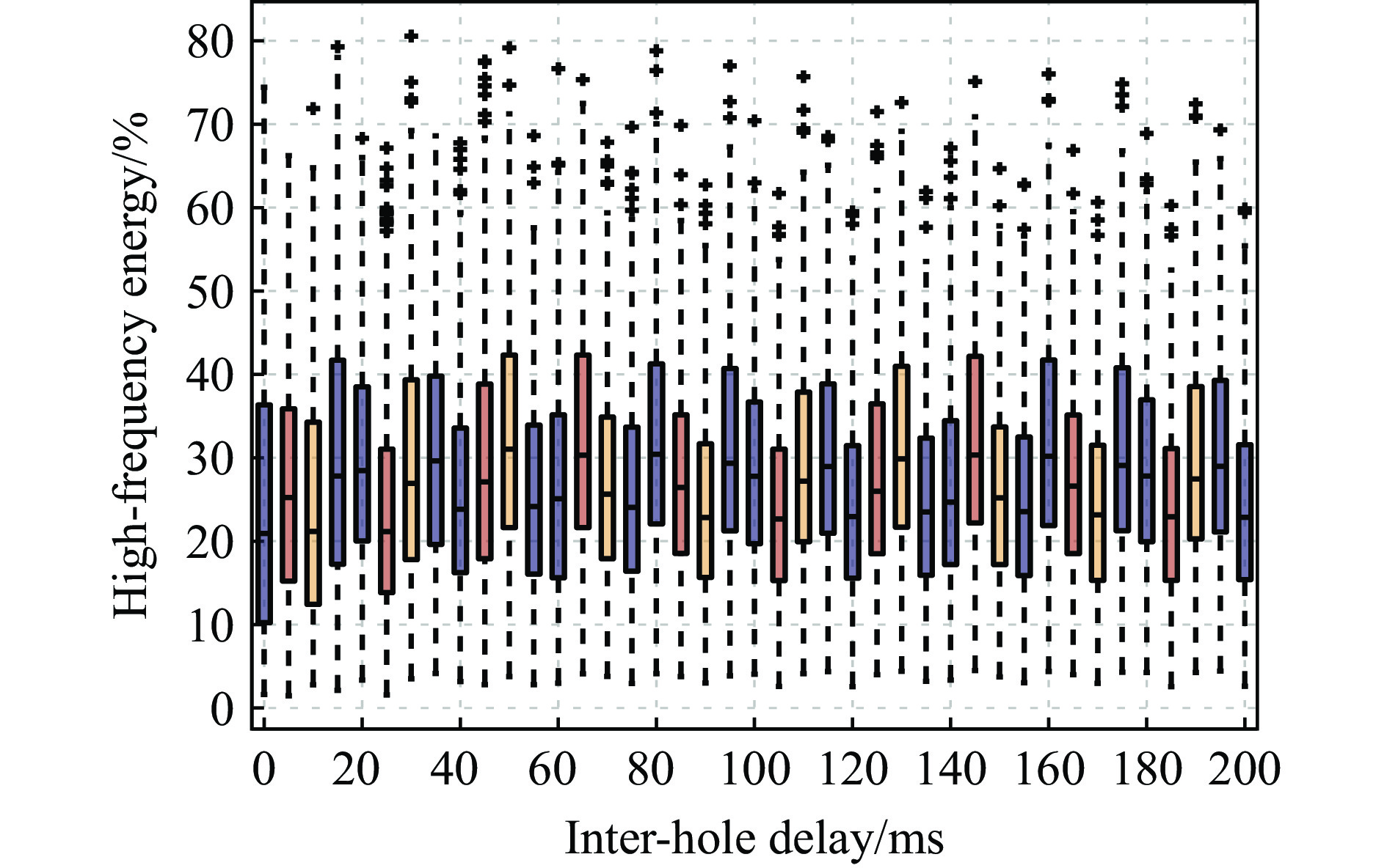
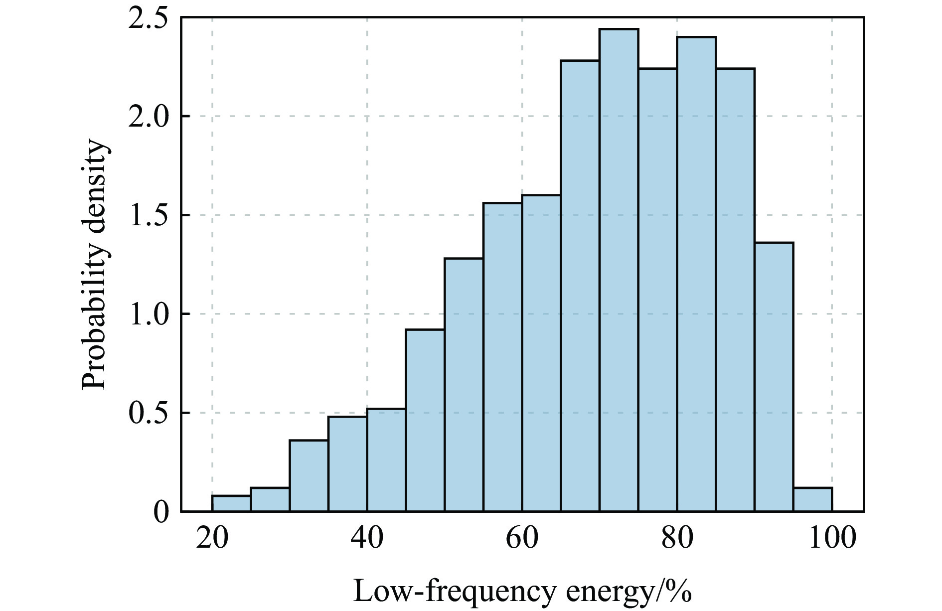
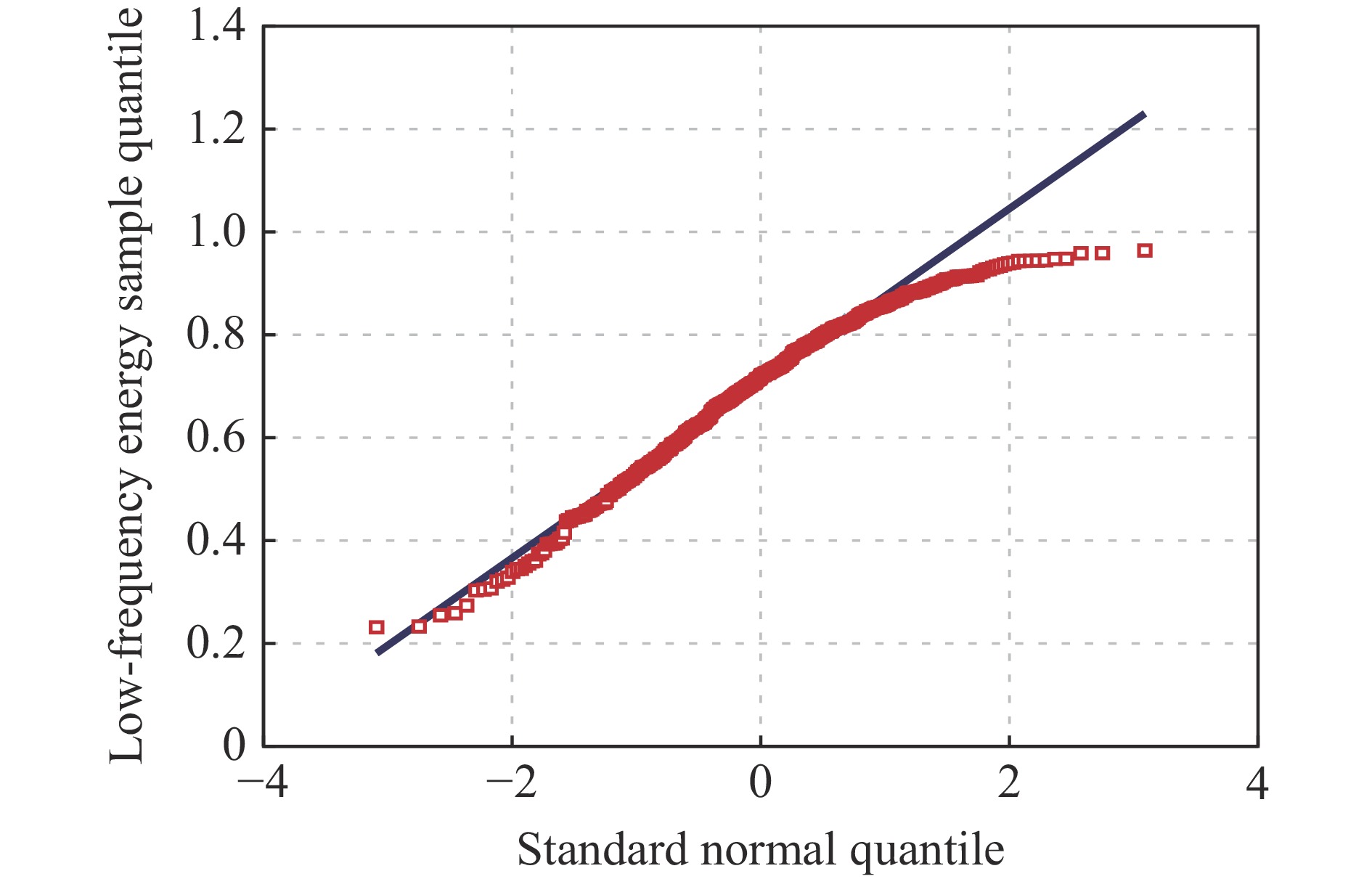
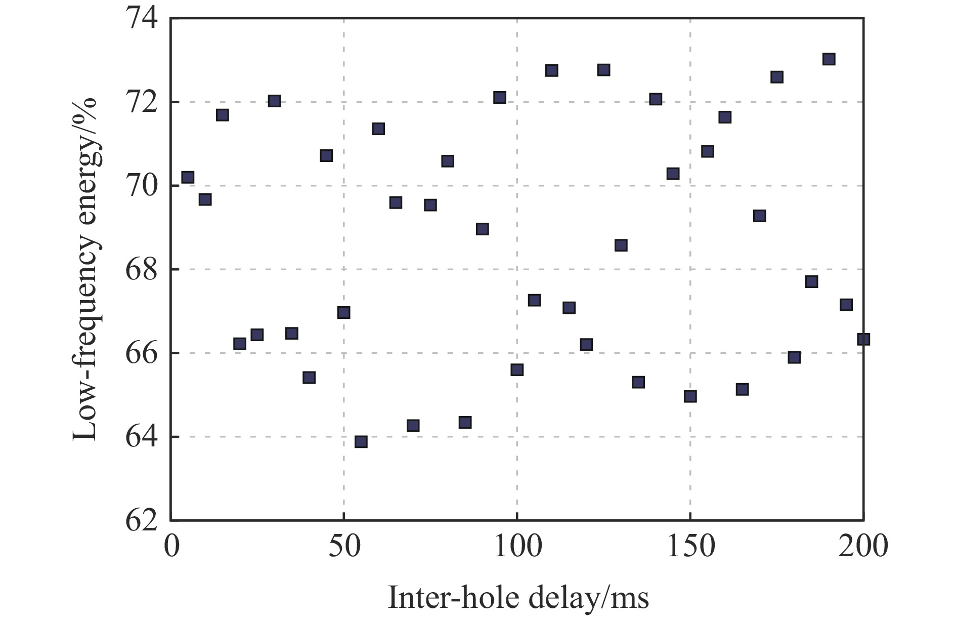
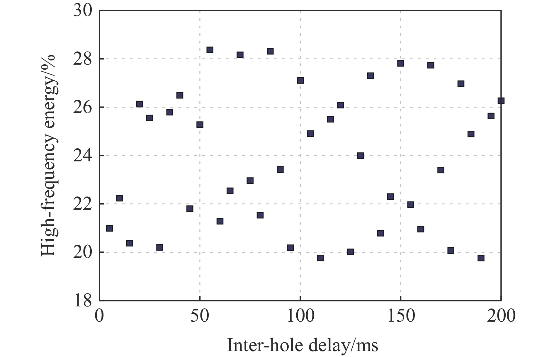
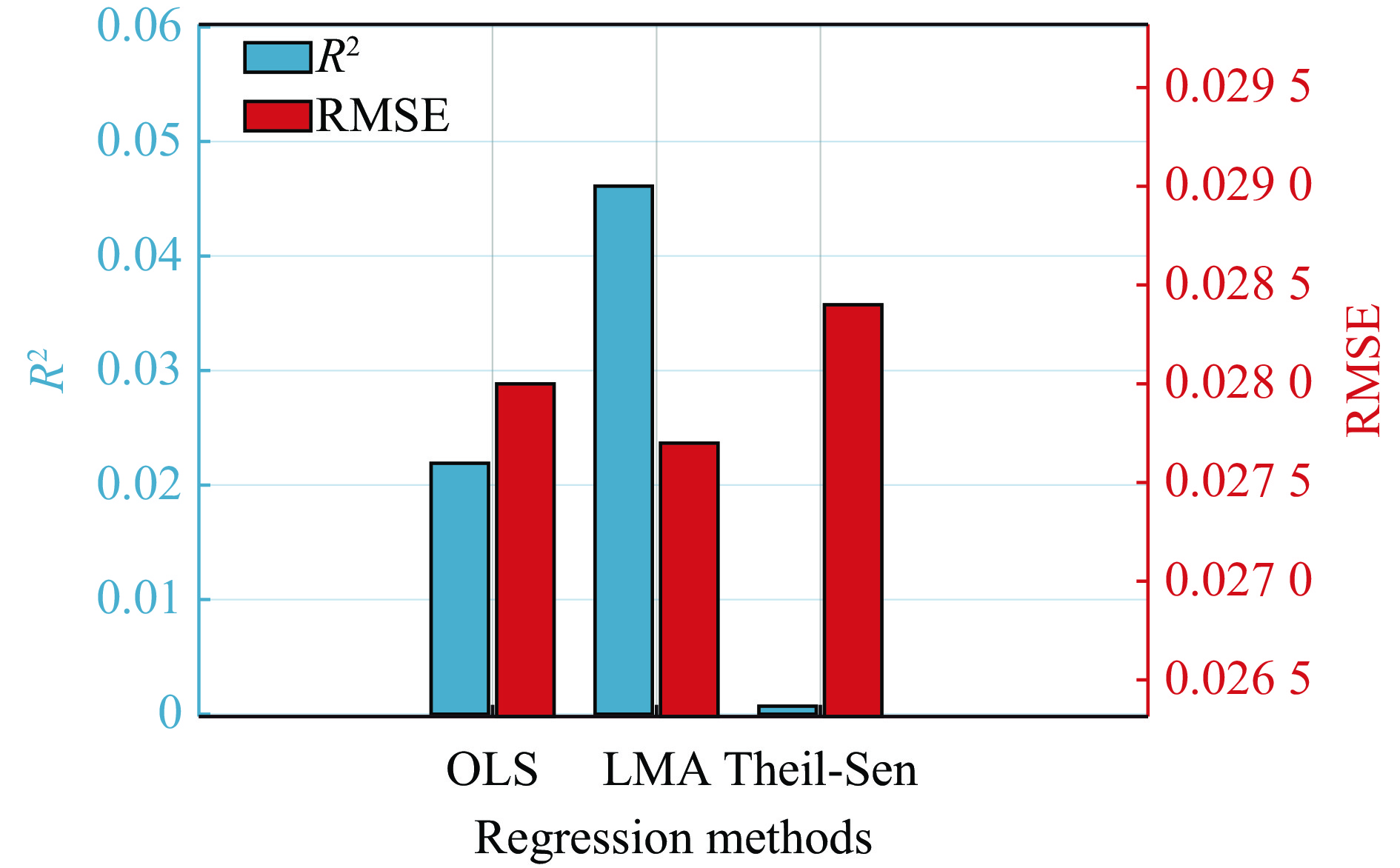
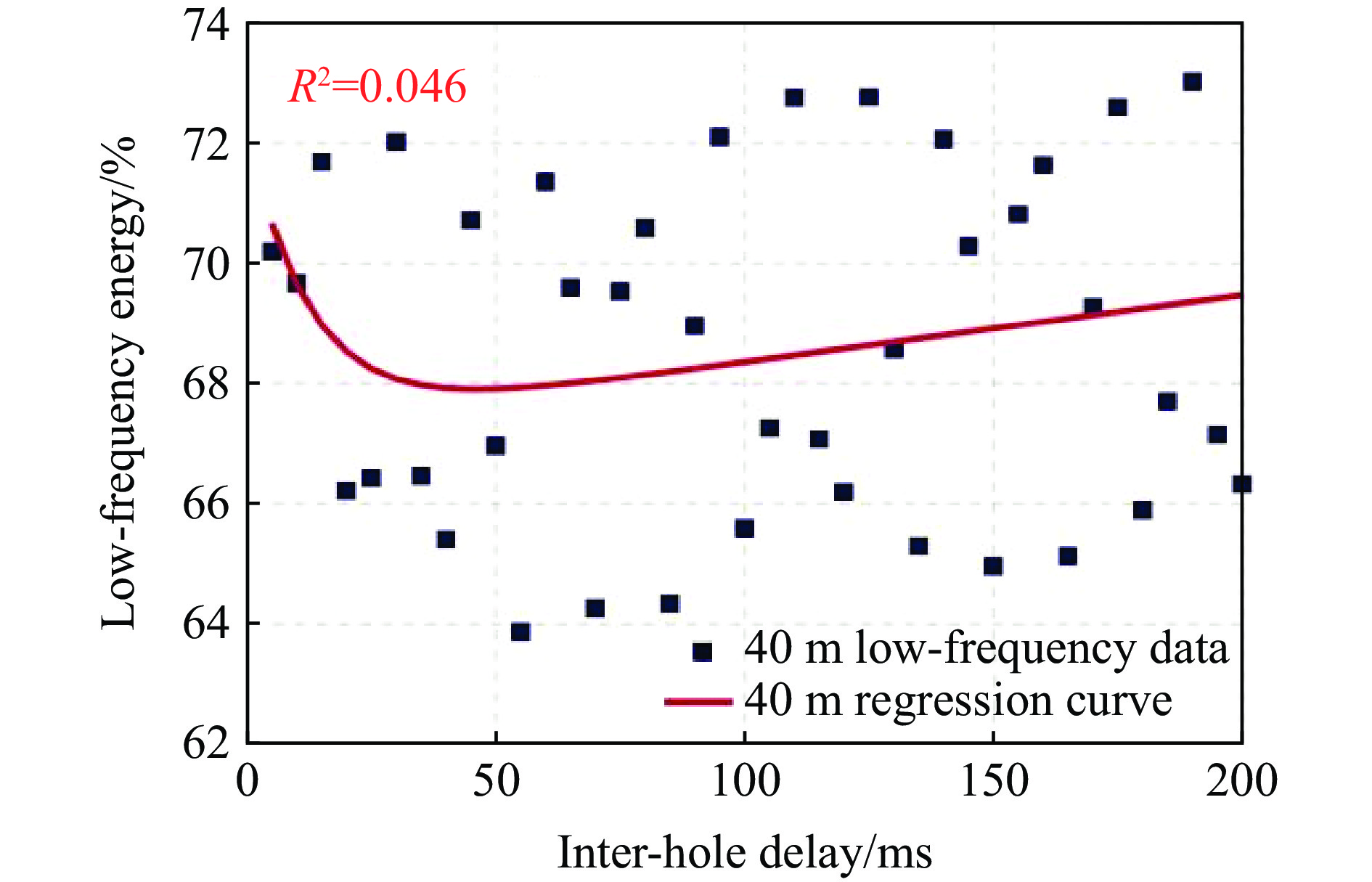
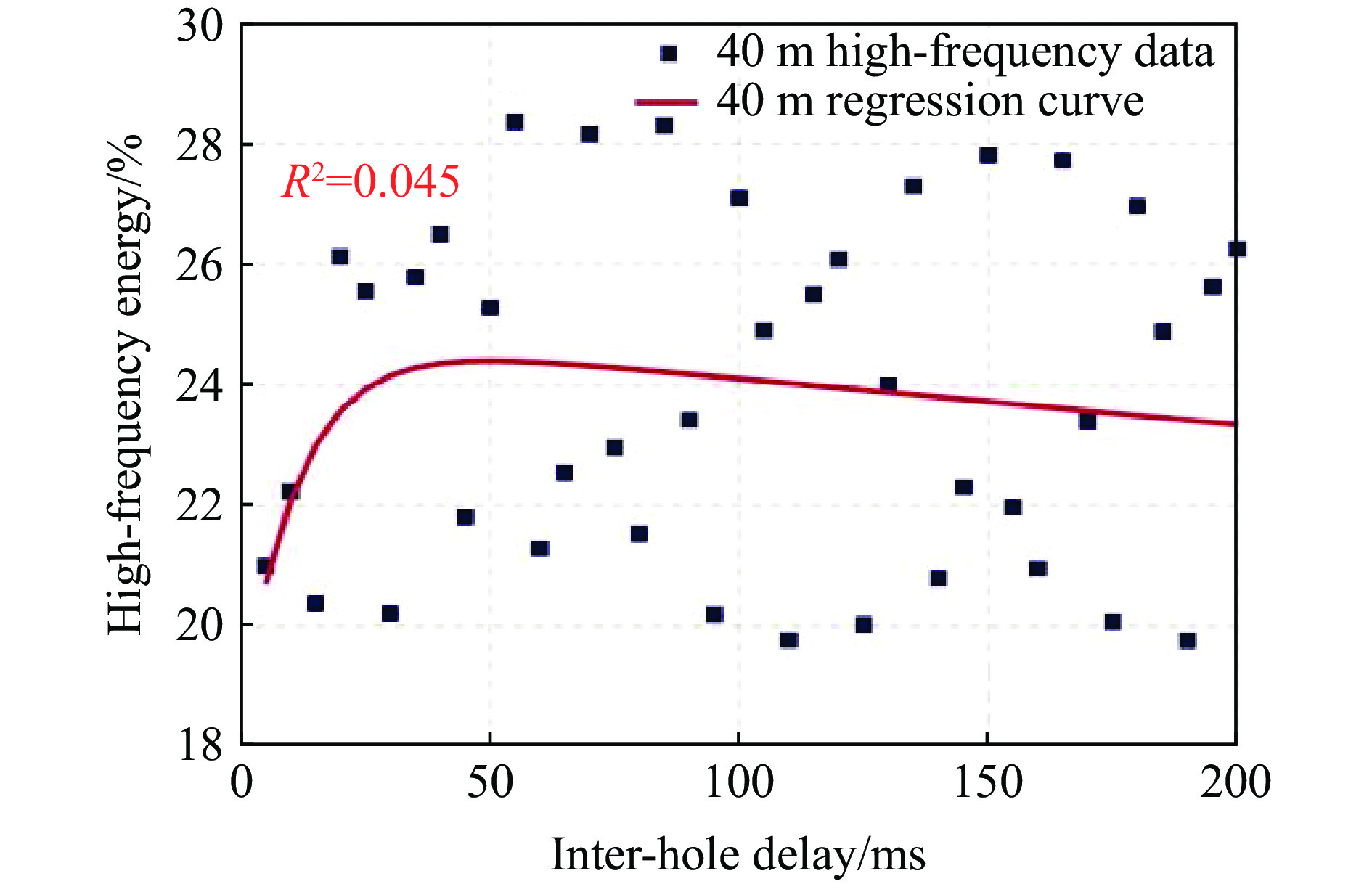
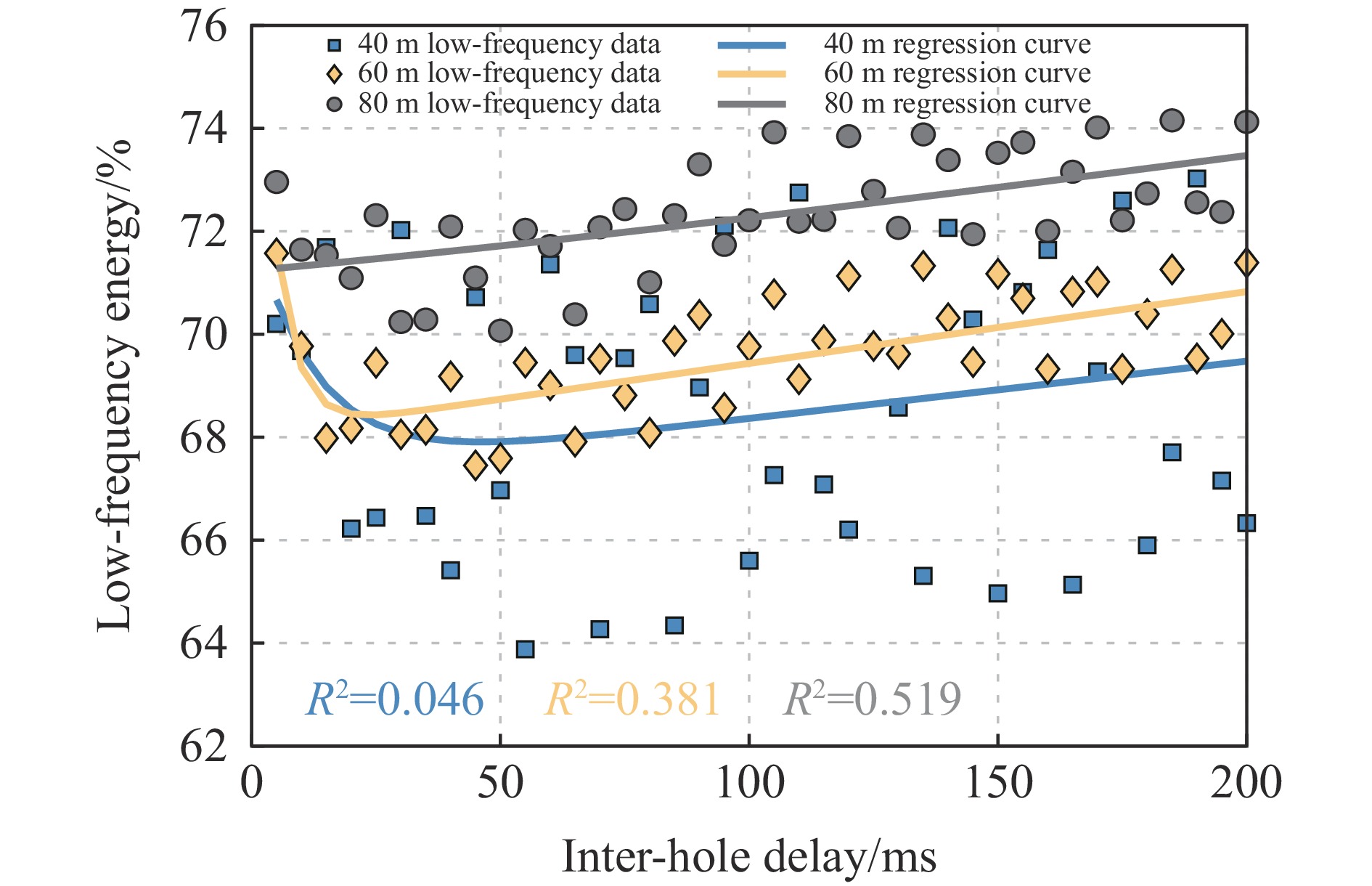
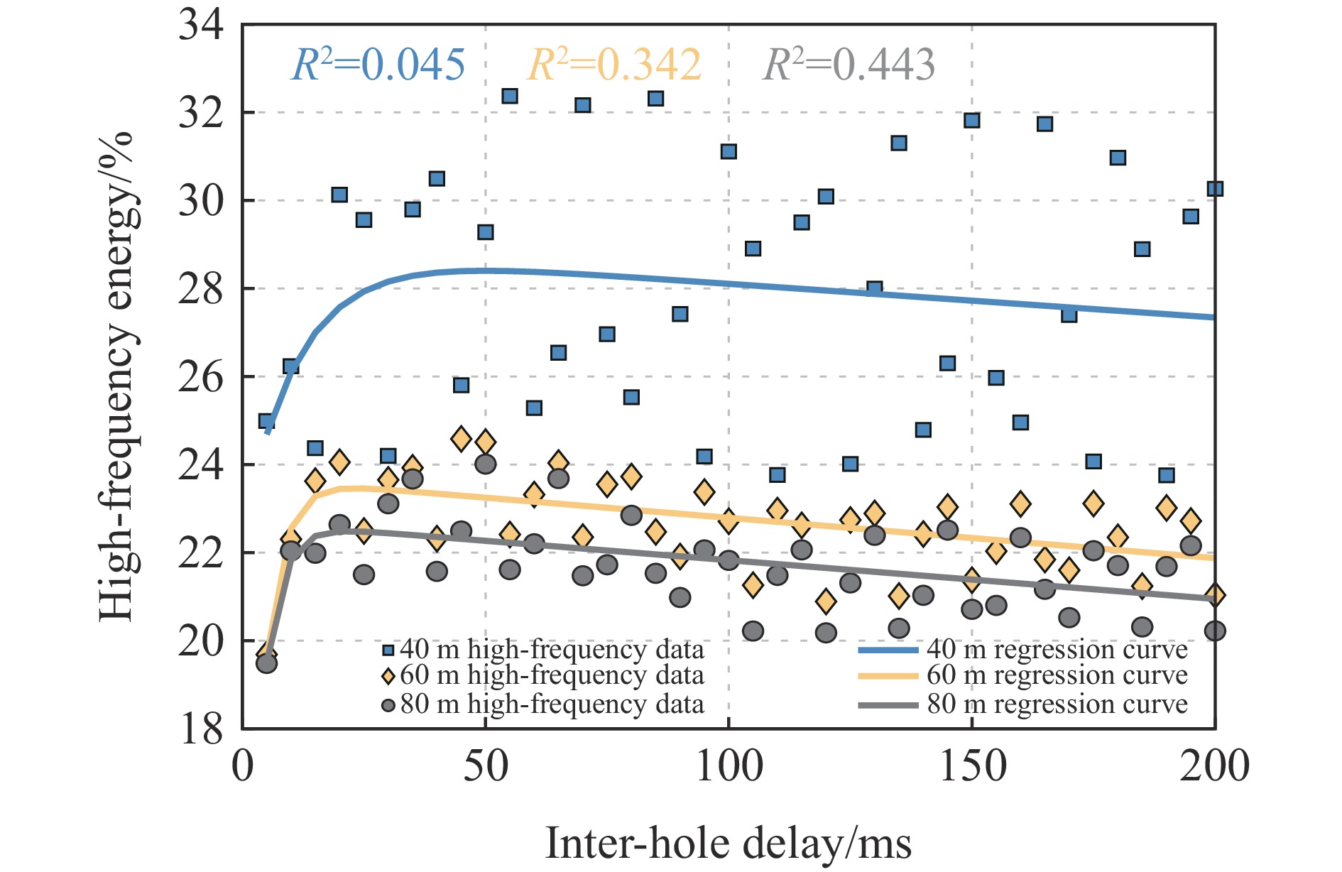
To investigate the influence of inter-hole delay on the intensity and frequency characteristics of blasting vibrations, an effective simulation of single-hole blasting vibration waveforms was achieved based on a single-hole blasting vibration prediction model. Subsequently, incorporating Blair's nonlinear superposition theory, a group-hole blasting vibration prediction model was constructed that can reflect the nonlinear vibration relationship between holes. Using a copper mine in Jiangxi Province as the engineering context, the constrained-traversal algorithm was employed to optimize the parameters of the single-hole prediction model. The simulated waveform output by this model exhibits a peak velocity error of 0.7% compared to the measured single-hole waveform, with identical predictions for the dominant frequency. The peak velocity error between the simulated waveform output by the group-hole blast vibration prediction model and the measured group-hole waveform is 3.9%, with the dominant frequency prediction being completely consistent. This fully validates the effectiveness of both the single-hole and group-hole blast vibration prediction models. Based on dual-hole blasting vibration experiments, employing Monte Carlo methodology, the model generated1000 sets of single-hole simulated waveforms. From these, 500 sets of dual-hole blasting vibration waveform characteristics (peak velocity, dominant frequency, and energy distribution across frequency bands) were extracted to construct a sample set. Subsequently, statistical analysis was conducted on the damping rate, dominant frequency, and energy distribution across frequency bands for the superimposed vibration waves of dual-hole blasts at different delay times and blast center distances, using the upper limit of the 95% confidence interval and the mean value. Results indicate that at the same blast center distance, as the delay time increases, the damping rate first increases and then stabilizes. At the same time the dominant frequency gradually decreases, with high-frequency energy progressively shifting toward low-frequency energy. At different blast centers, as the blast center distance increases, the damping rate generally decreases across various delay times. The dominant frequency shifts toward lower frequencies, resulting in an overall increase in low-frequency energy and an overall decrease in high-frequency energy. The Monte Carlo method, based on extensive simulations and statistical analysis, not only reveals the random characteristics of blasting vibration signals but also enables quantitative analysis of their time-domain and frequency-domain features, holding significant theoretical and engineering value.
To investigate the influence of inter-hole delay on the intensity and frequency characteristics of blasting vibrations, an effective simulation of single-hole blasting vibration waveforms was achieved based on a single-hole blasting vibration prediction model. Subsequently, incorporating Blair's nonlinear superposition theory, a group-hole blasting vibration prediction model was constructed that can reflect the nonlinear vibration relationship between holes. Using a copper mine in Jiangxi Province as the engineering context, the constrained-traversal algorithm was employed to optimize the parameters of the single-hole prediction model. The simulated waveform output by this model exhibits a peak velocity error of 0.7% compared to the measured single-hole waveform, with identical predictions for the dominant frequency. The peak velocity error between the simulated waveform output by the group-hole blast vibration prediction model and the measured group-hole waveform is 3.9%, with the dominant frequency prediction being completely consistent. This fully validates the effectiveness of both the single-hole and group-hole blast vibration prediction models. Based on dual-hole blasting vibration experiments, employing Monte Carlo methodology, the model generated
, Available online , doi: 10.11883/bzycj-2025-0304
Abstract:
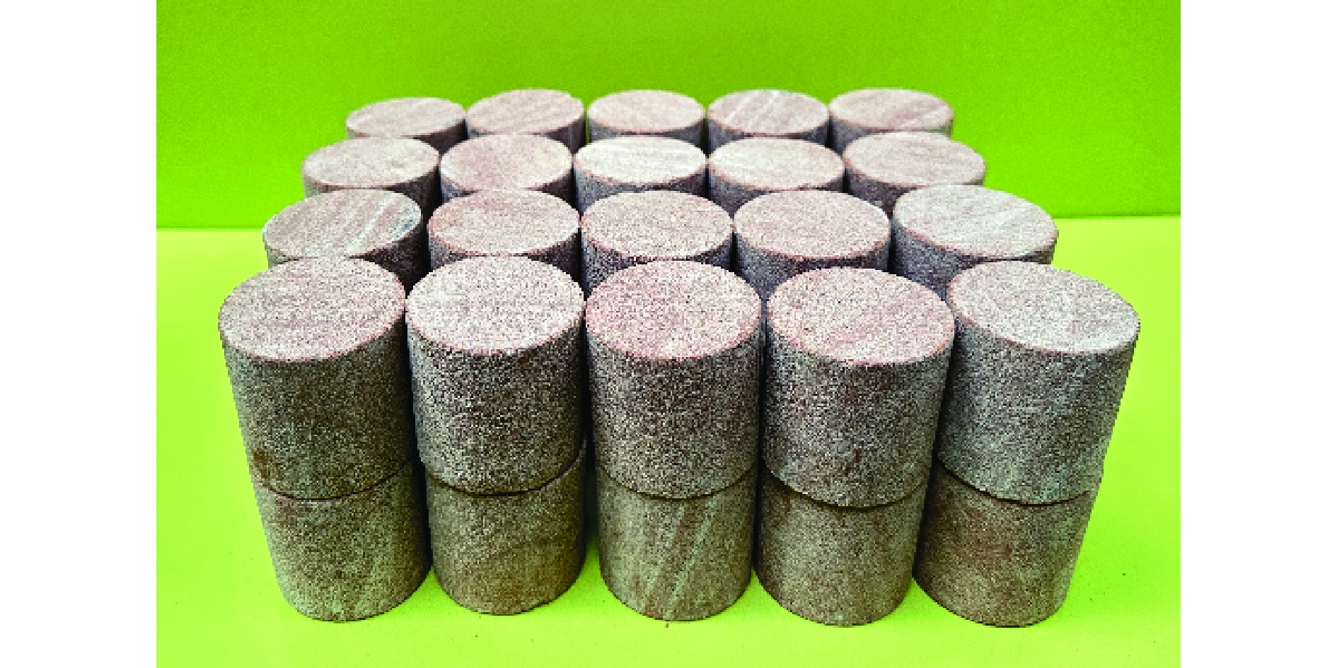
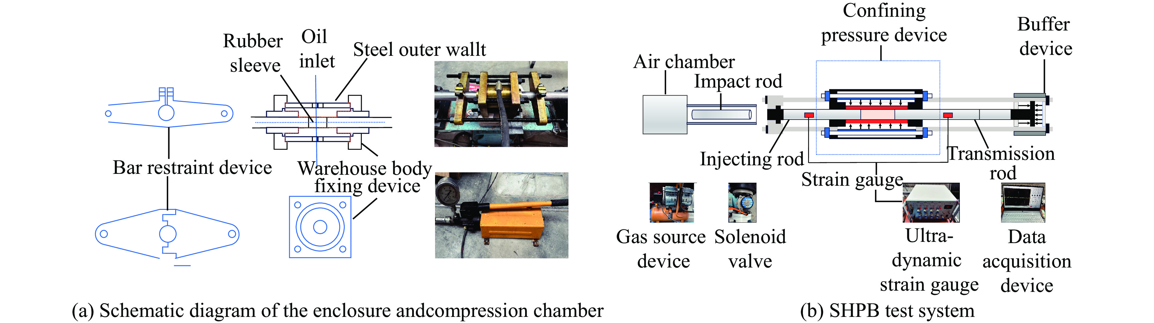
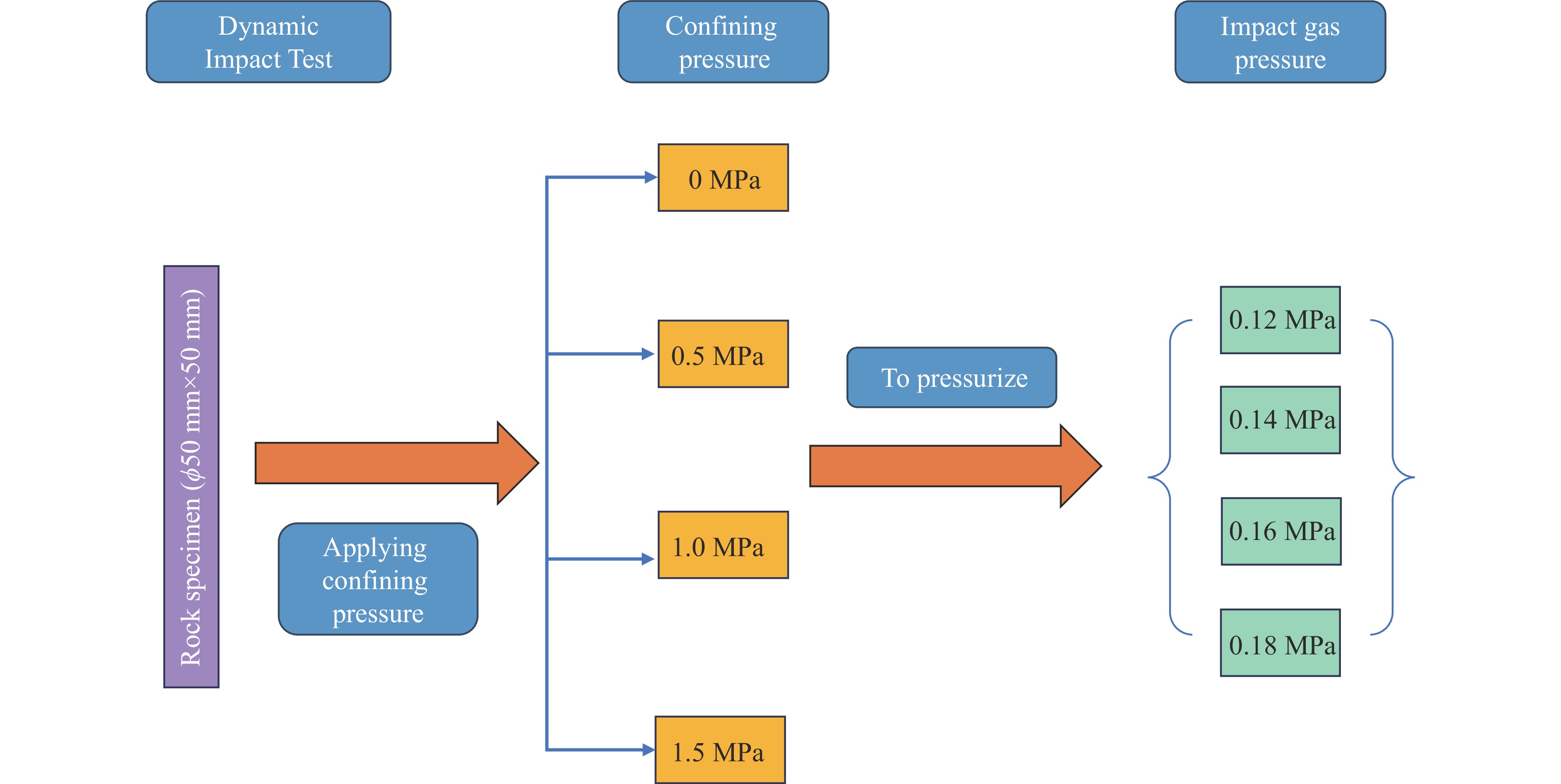
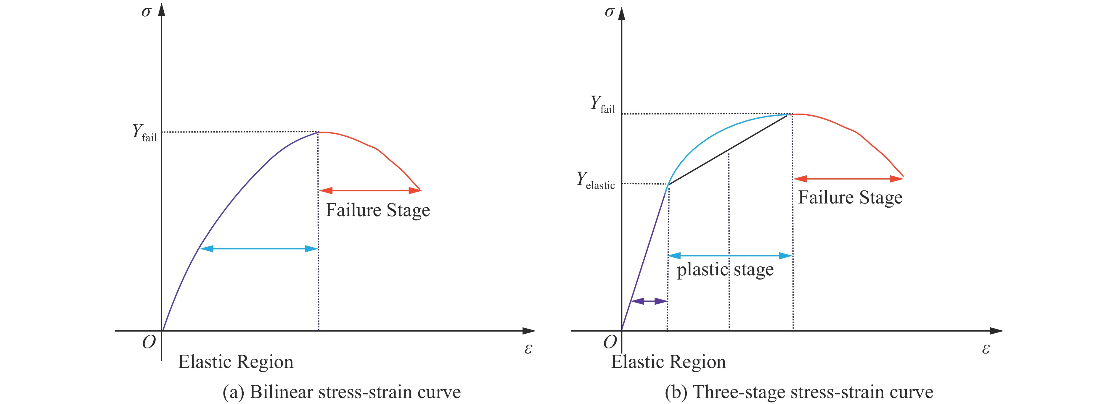
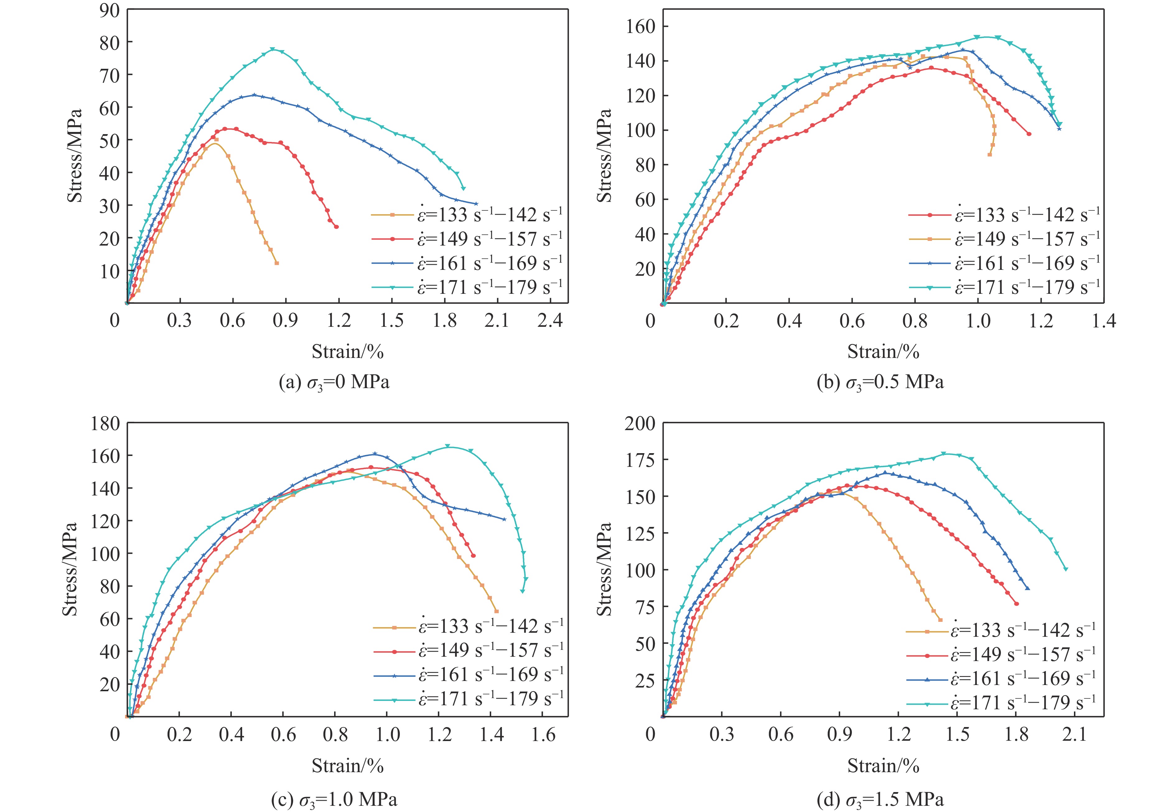
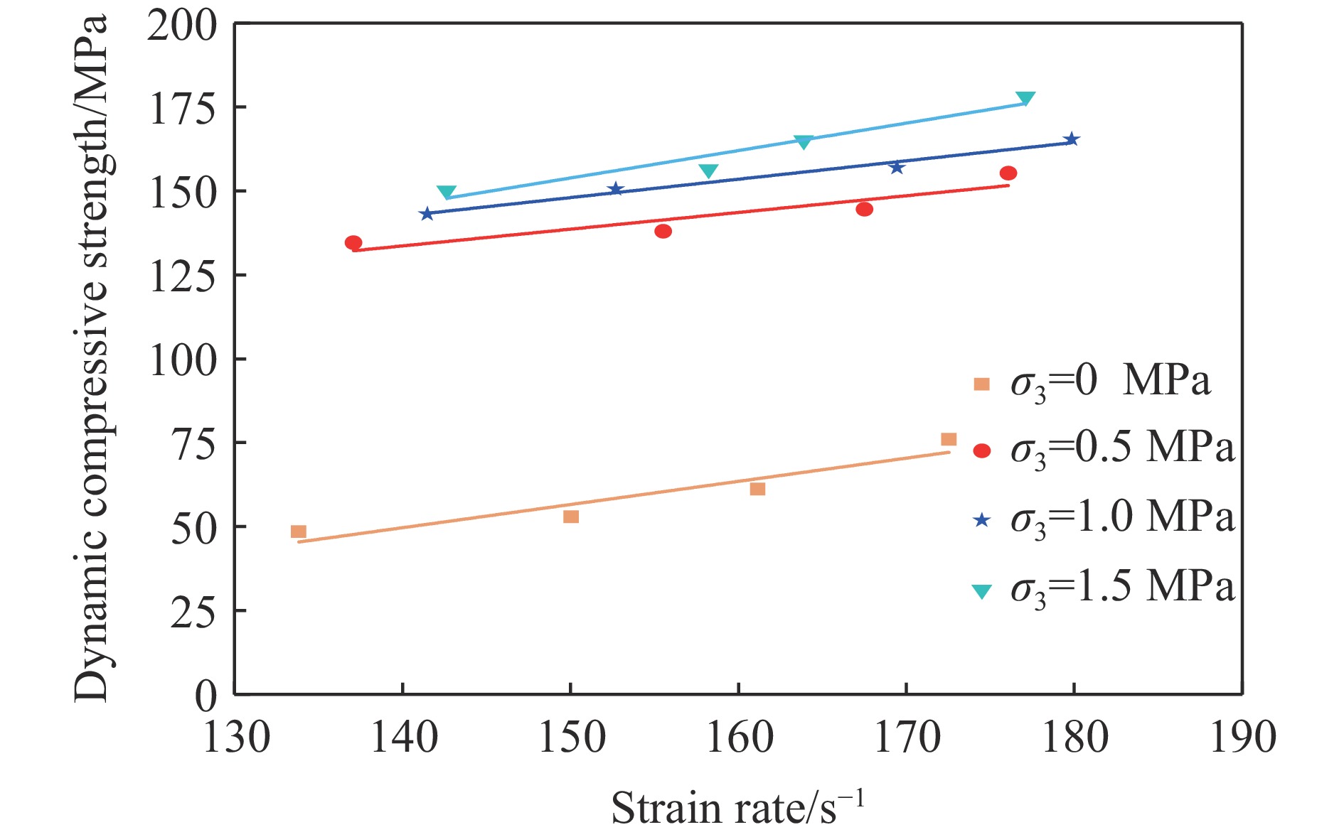
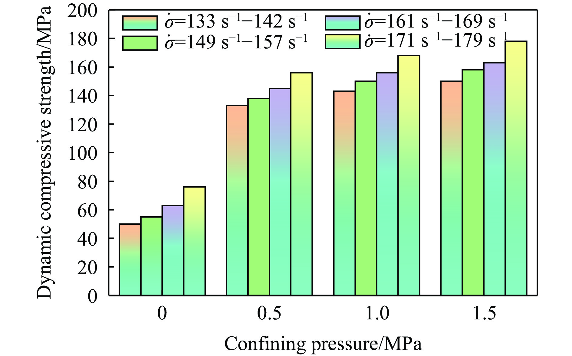
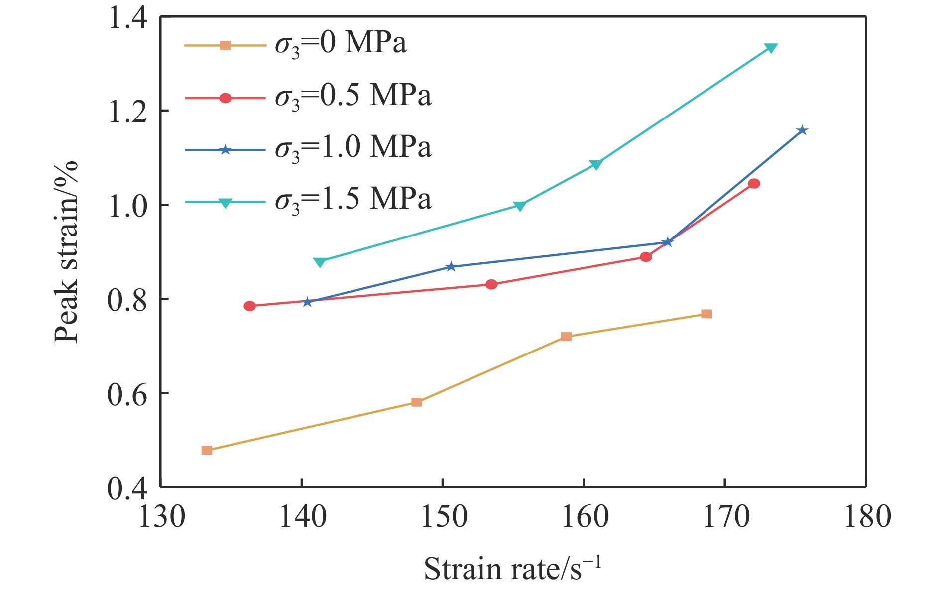
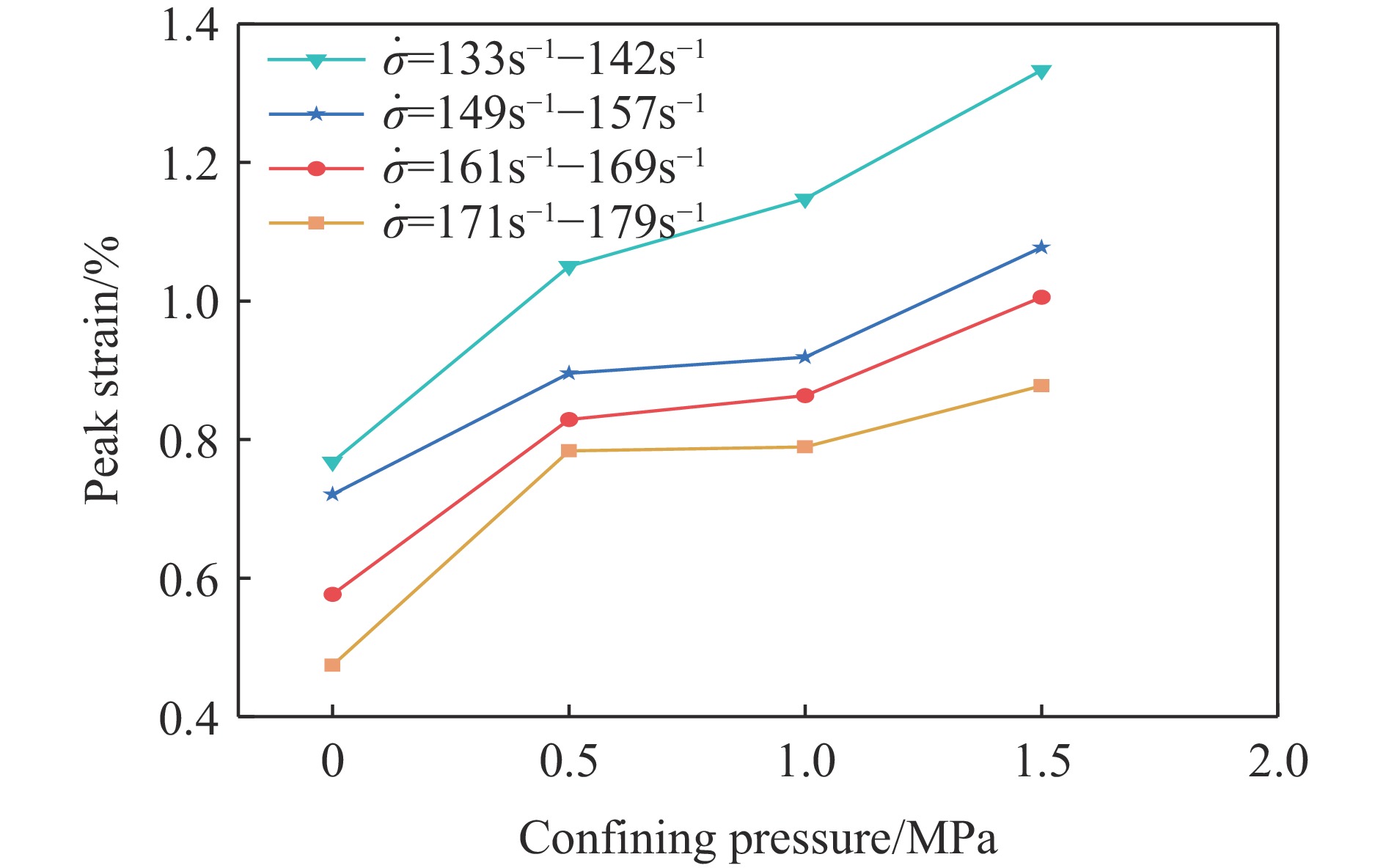
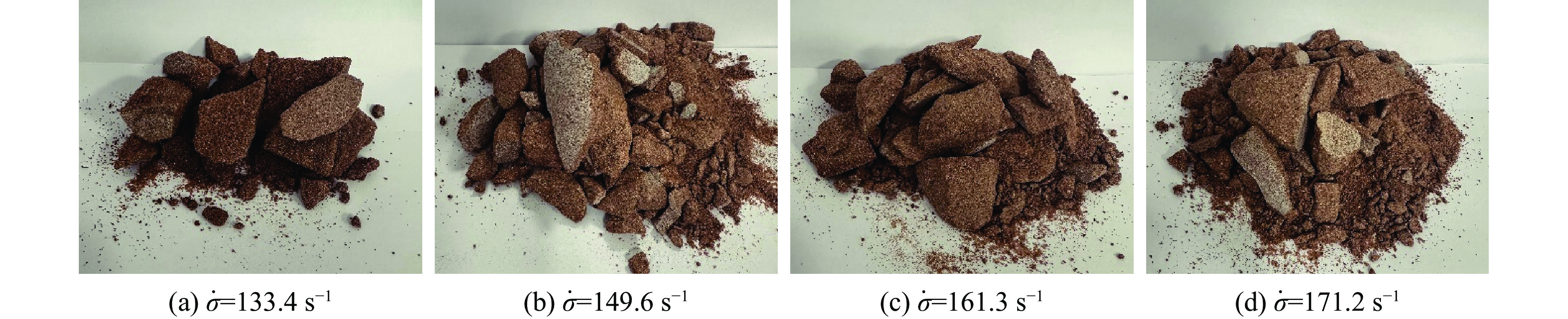
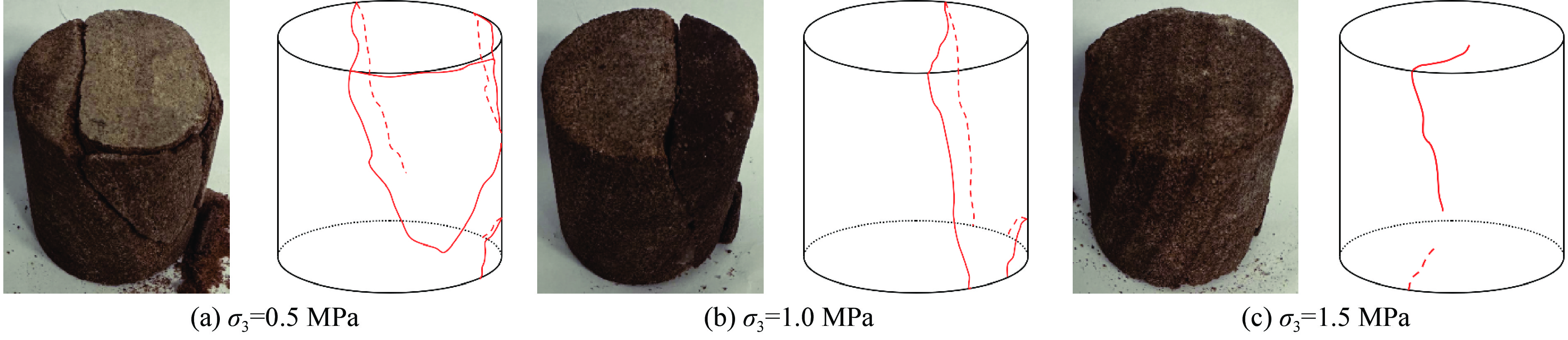
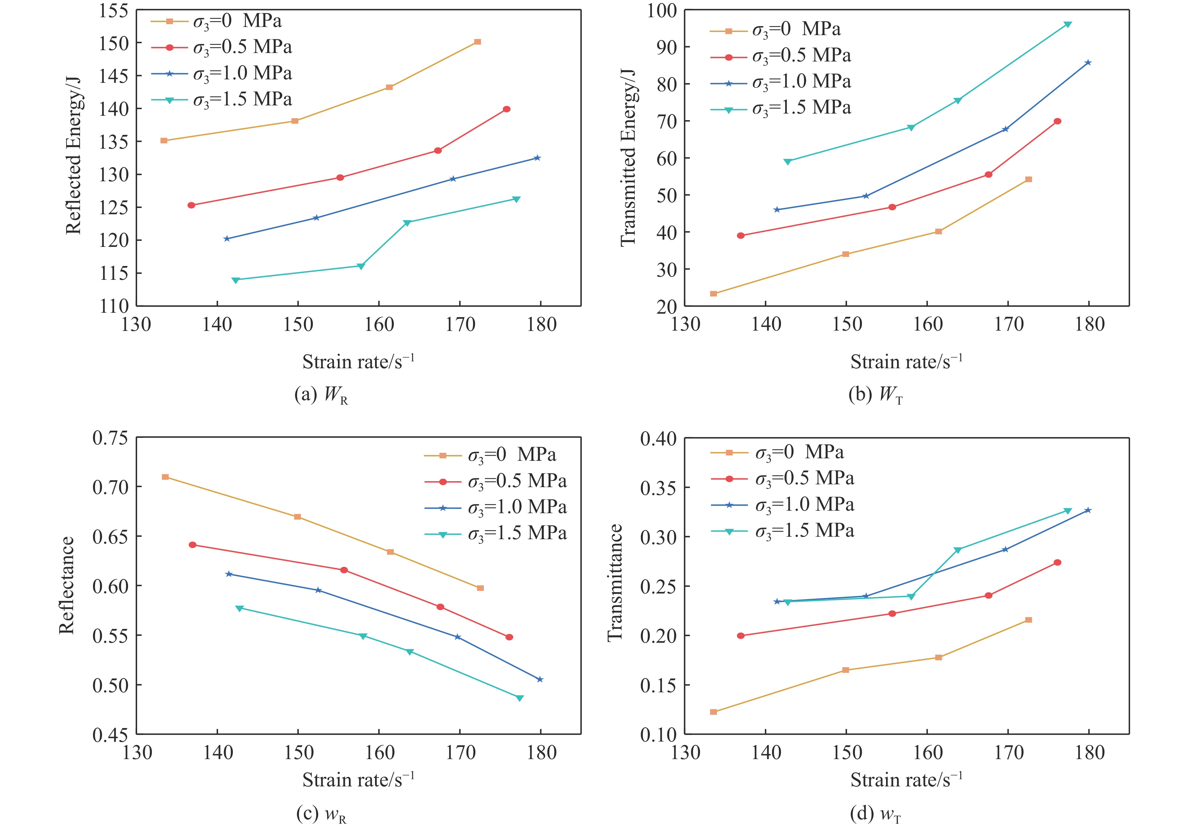
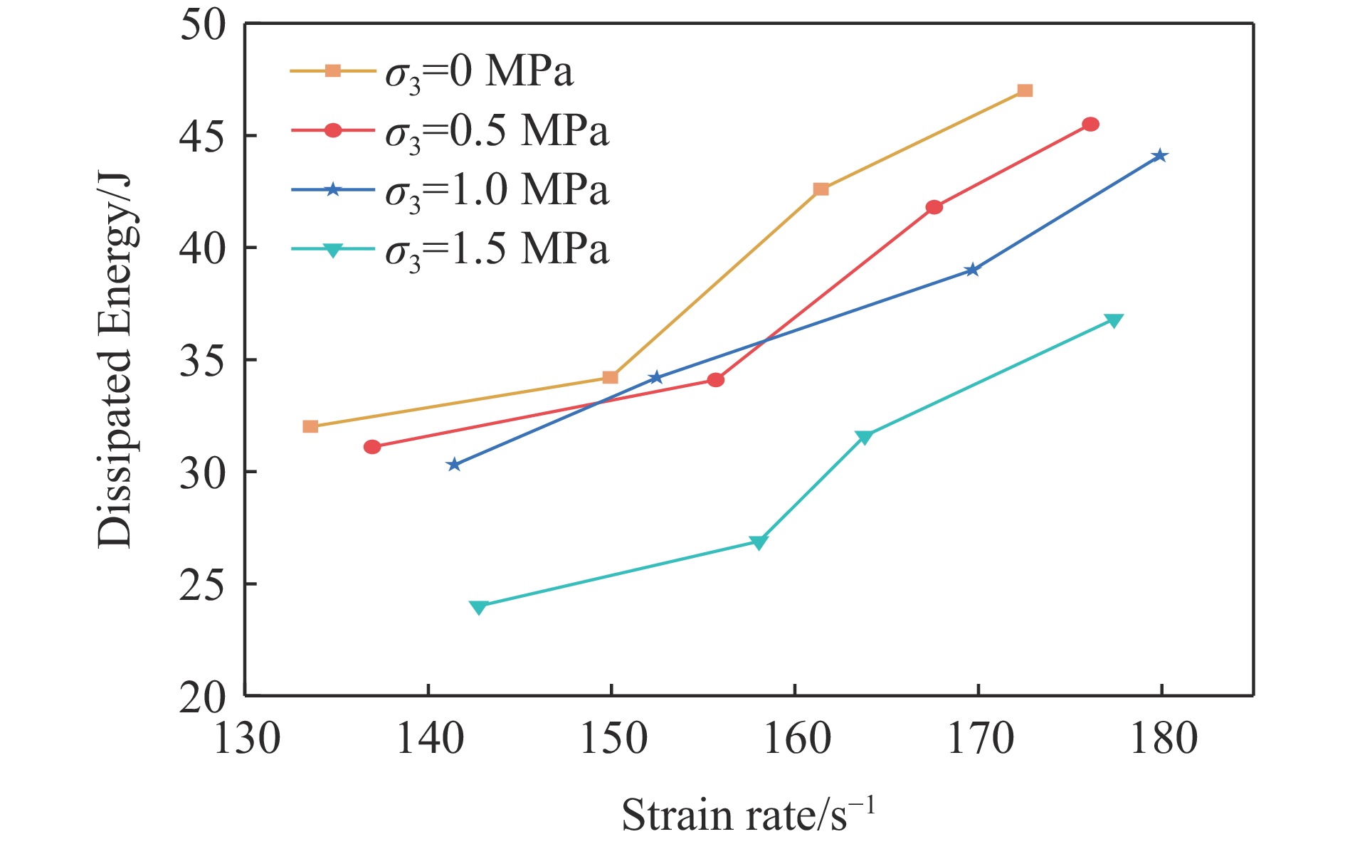
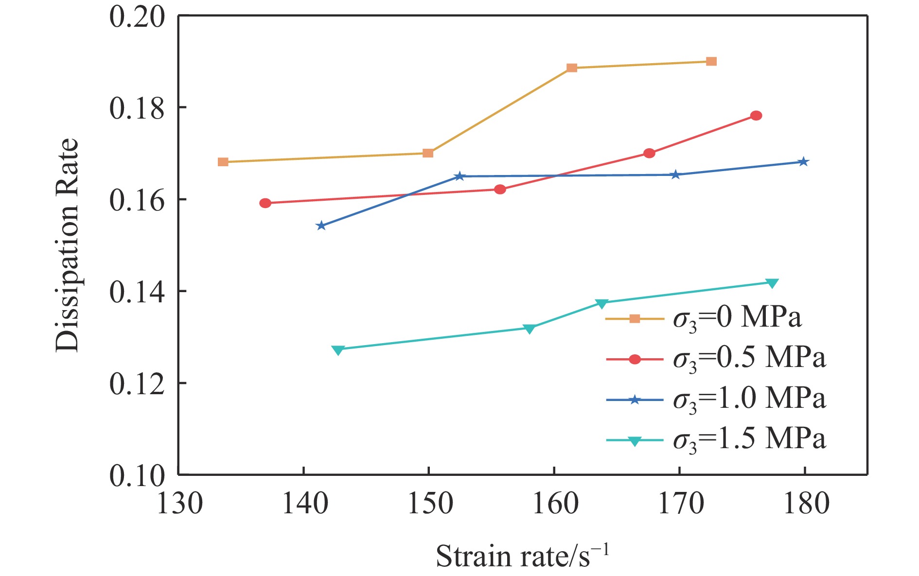
To investigate the disturbance caused by blasting in the excavation process of tunnel and coal mine surrounding rock, it is urgent to clarify the mechanical response, failure mode and energy dissipation characteristics of red sandstone under dynamic load under confining pressure. In this study, the Split Hopkinson pressure bar (SHPB) test system with a self-developed active confining pressure control device was used to carry out dynamic compression tests on red sandstone specimens under different confining pressure levels, to explore the dynamic mechanical response, failure mode and energy dissipation mechanism of red sandstone under impact load. The test results show that the stress-strain curve presents a “two stages” characteristics under unconfined condition. and the stress-strain curve changes from a “two stages” to a “three stages” pattern with the increase of confining pressure. The confining pressure significantly enhances the dynamic compressive strength and peak strain of red sandstone, both of which show significant strain rate effect and confining pressure effect. In terms of failure mode and energy dissipation, the rock specimen is crushed when subjected to higher strain rate at unconfined condition. Under confining pressure, the damage degree of the sample is significantly reduced, and finally resulting in compression-shear failure. Under the same confining pressure, the reflection energy and reflectivity increase with the increase of strain rate, while the transmission energy increases with the increase of strain rate and the transmittance decreases with the increase of strain rate. Under the same strain rate, with the increase of confining pressure, the rock reflection energy and reflectivity decrease, the transmission energy and transmittance increase. When the specimen is dynamically damaged, the dissipation energy is regulated by strain rate and confining pressure. When the confining pressure is constant, the dissipation energy and dissipation rate increase with the increase of strain rate. When the strain rate is constant, both the dissipation energy and dissipation rate decrease with the increase of confining pressure.
To investigate the disturbance caused by blasting in the excavation process of tunnel and coal mine surrounding rock, it is urgent to clarify the mechanical response, failure mode and energy dissipation characteristics of red sandstone under dynamic load under confining pressure. In this study, the Split Hopkinson pressure bar (SHPB) test system with a self-developed active confining pressure control device was used to carry out dynamic compression tests on red sandstone specimens under different confining pressure levels, to explore the dynamic mechanical response, failure mode and energy dissipation mechanism of red sandstone under impact load. The test results show that the stress-strain curve presents a “two stages” characteristics under unconfined condition. and the stress-strain curve changes from a “two stages” to a “three stages” pattern with the increase of confining pressure. The confining pressure significantly enhances the dynamic compressive strength and peak strain of red sandstone, both of which show significant strain rate effect and confining pressure effect. In terms of failure mode and energy dissipation, the rock specimen is crushed when subjected to higher strain rate at unconfined condition. Under confining pressure, the damage degree of the sample is significantly reduced, and finally resulting in compression-shear failure. Under the same confining pressure, the reflection energy and reflectivity increase with the increase of strain rate, while the transmission energy increases with the increase of strain rate and the transmittance decreases with the increase of strain rate. Under the same strain rate, with the increase of confining pressure, the rock reflection energy and reflectivity decrease, the transmission energy and transmittance increase. When the specimen is dynamically damaged, the dissipation energy is regulated by strain rate and confining pressure. When the confining pressure is constant, the dissipation energy and dissipation rate increase with the increase of strain rate. When the strain rate is constant, both the dissipation energy and dissipation rate decrease with the increase of confining pressure.
, Available online , doi: 10.11883/bzycj-2025-0287
Abstract:
The shock wave load generated by underwater explosions exhibits significant variability and uncertainty. To address the prediction bias caused by classical deterministic empirical models that ignore this uncertainty, an uncertainty analysis of both model parameters and model errors was conducted for key load model parameters—peak pressure pm, time constant θ, impulse I, and shock wave specific energy density es, based on 682 sets of underwater explosion test data. Within the framework of the empirical model Cole, a Bayesian probabilistic model for underwater explosion shock wave loads was developed. Bayesian inference methods were employed to update and calibrate the model parameters, enabling a probabilistic characterization of the explosion shock wave load. The results show that the coefficient of variation for the calculated parameters of the model Cole ranges from 0.03 to 0.48, while the coefficient of variation for model errors lies between 0.19 and 0.38. Among these, only the modelling error for peak pressure approximately follows a normal distribution. In contrast the modelling errors for the time constant, impulse, and specific energy density exhibit distinctly skewed distributions. Moreover, the model errors gradually stabilize as the scaled distance increases. Under the condition of limited experimental samples, the Bayesian probabilistic model significantly improves parameter estimation accuracy, effectively reduces model uncertainty, and achieves a reasonable balance between model precision and experimental cost. The analysis demonstrates that the developed Bayesian probabilistic model for underwater explosion shock wave loads can reasonably characterize the uncertainty of the loads. It provides stochastic inputs that explicitly account for load variability for the reliability-based blast-resistant design of underwater structures, and offers a more comprehensive basis for engineering risk assessment and probabilistic analysis.
The shock wave load generated by underwater explosions exhibits significant variability and uncertainty. To address the prediction bias caused by classical deterministic empirical models that ignore this uncertainty, an uncertainty analysis of both model parameters and model errors was conducted for key load model parameters—peak pressure pm, time constant θ, impulse I, and shock wave specific energy density es, based on 682 sets of underwater explosion test data. Within the framework of the empirical model Cole, a Bayesian probabilistic model for underwater explosion shock wave loads was developed. Bayesian inference methods were employed to update and calibrate the model parameters, enabling a probabilistic characterization of the explosion shock wave load. The results show that the coefficient of variation for the calculated parameters of the model Cole ranges from 0.03 to 0.48, while the coefficient of variation for model errors lies between 0.19 and 0.38. Among these, only the modelling error for peak pressure approximately follows a normal distribution. In contrast the modelling errors for the time constant, impulse, and specific energy density exhibit distinctly skewed distributions. Moreover, the model errors gradually stabilize as the scaled distance increases. Under the condition of limited experimental samples, the Bayesian probabilistic model significantly improves parameter estimation accuracy, effectively reduces model uncertainty, and achieves a reasonable balance between model precision and experimental cost. The analysis demonstrates that the developed Bayesian probabilistic model for underwater explosion shock wave loads can reasonably characterize the uncertainty of the loads. It provides stochastic inputs that explicitly account for load variability for the reliability-based blast-resistant design of underwater structures, and offers a more comprehensive basis for engineering risk assessment and probabilistic analysis.
, Available online , doi: 10.11883/bzycj-2025-0248
Abstract:
When a projectile impacts a thin plate at hypervelocity, the projectile material usually undergoes deformation, fragmentation, and even phase transition under the action of a complex wave system, forming a secondary debris cloud. It has been shown that the head shape of the rod affects the hypervelocity impact between the rod and a thin plate. A series of SPH (Smoothed Particle Hydrodynamics) numerical simulations of the hypervelocity impact by rods with flat head, hemispherical head, and cone head at impact velocities of 3.30 km/s and 6.0 km/s and length-to-diameter ratios of 2/1 and 3/1 were carried out. Simulation results show that the intensity of the shock wave and the failure in the material are affected by the head shape of the rod. With the impact across the plate, the mass loss and kinetic energy loss of the rod are related to the head shape. Obtuse cone head and flat head impact produce the strongest shock wave, most intense projectile fragmentation, and largest loss of rod mass and kinetic energy. A model of the interaction between the rod and the plate, as well as the shock wave generation during the impact, was built. The model shows that there exists a critical half-cone angle (related to the impact velocity and the target material), which leads to continuous interaction between rod and plate and makes the fragmentation of the rod projectile the most violent. For the hypervelocity impact of projectiles with different shapes, in a previous work, the impact-induced shock wave in a cone is more severe than that of a sphere or a rod, while another work has an inconsistent result. The model was successfully used to explain the contradictory results. This paper can provide some references for the research of hypervelocity impact and the protection design of space debris.
When a projectile impacts a thin plate at hypervelocity, the projectile material usually undergoes deformation, fragmentation, and even phase transition under the action of a complex wave system, forming a secondary debris cloud. It has been shown that the head shape of the rod affects the hypervelocity impact between the rod and a thin plate. A series of SPH (Smoothed Particle Hydrodynamics) numerical simulations of the hypervelocity impact by rods with flat head, hemispherical head, and cone head at impact velocities of 3.30 km/s and 6.0 km/s and length-to-diameter ratios of 2/1 and 3/1 were carried out. Simulation results show that the intensity of the shock wave and the failure in the material are affected by the head shape of the rod. With the impact across the plate, the mass loss and kinetic energy loss of the rod are related to the head shape. Obtuse cone head and flat head impact produce the strongest shock wave, most intense projectile fragmentation, and largest loss of rod mass and kinetic energy. A model of the interaction between the rod and the plate, as well as the shock wave generation during the impact, was built. The model shows that there exists a critical half-cone angle (related to the impact velocity and the target material), which leads to continuous interaction between rod and plate and makes the fragmentation of the rod projectile the most violent. For the hypervelocity impact of projectiles with different shapes, in a previous work, the impact-induced shock wave in a cone is more severe than that of a sphere or a rod, while another work has an inconsistent result. The model was successfully used to explain the contradictory results. This paper can provide some references for the research of hypervelocity impact and the protection design of space debris.
, Available online , doi: 10.11883/bzycj-2025-0297
Abstract:
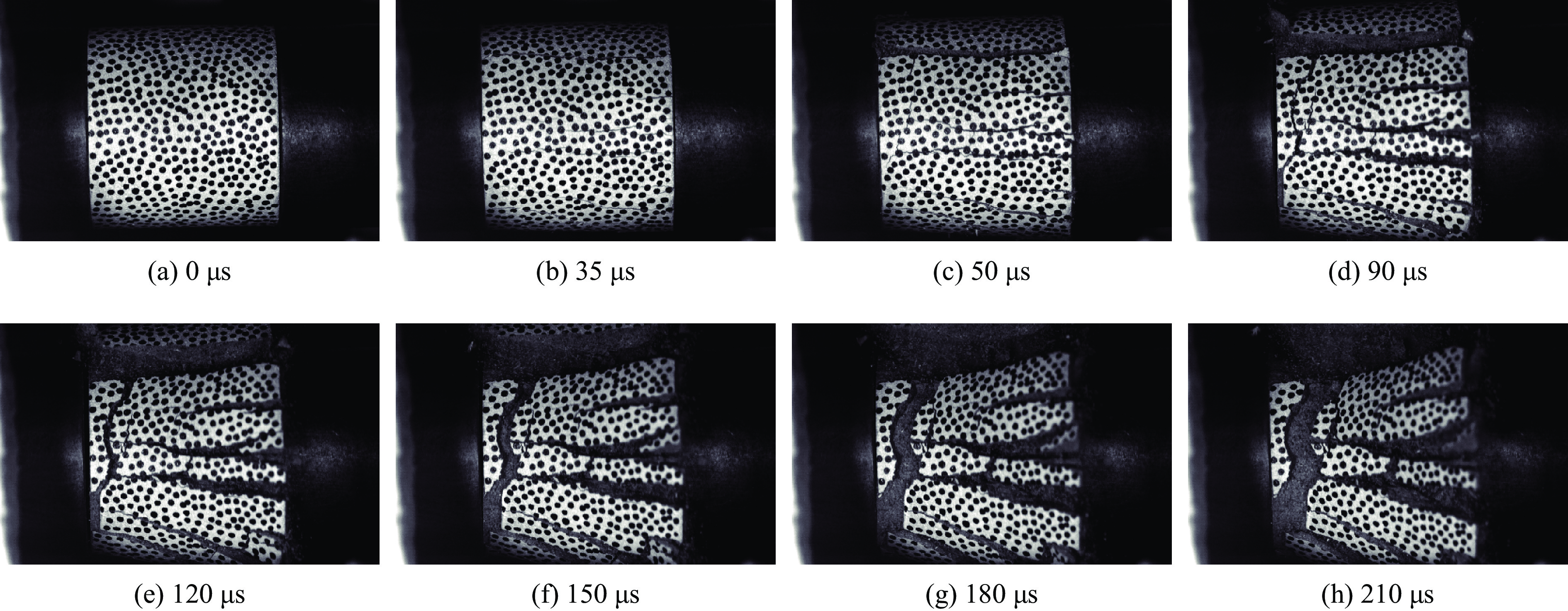
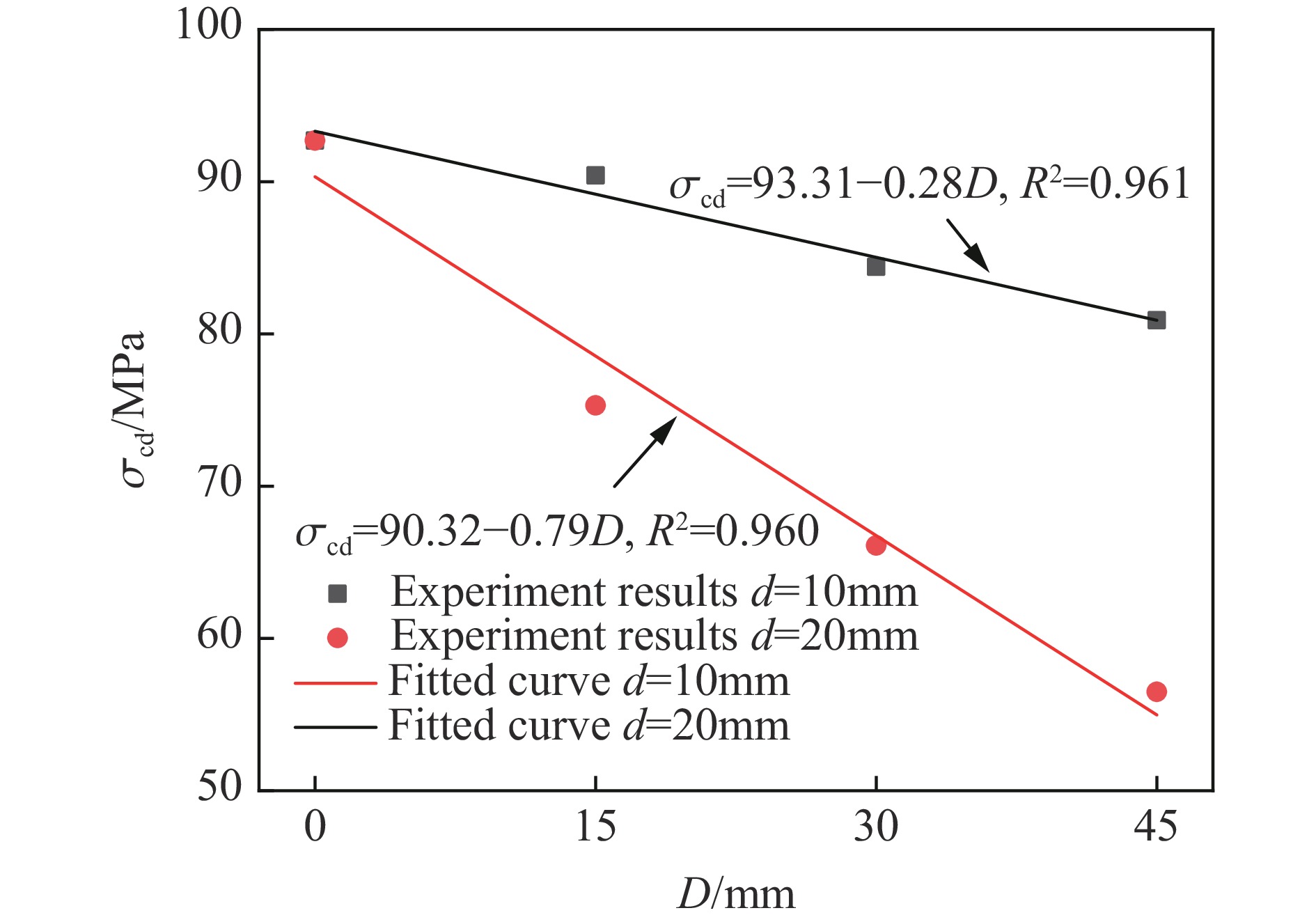
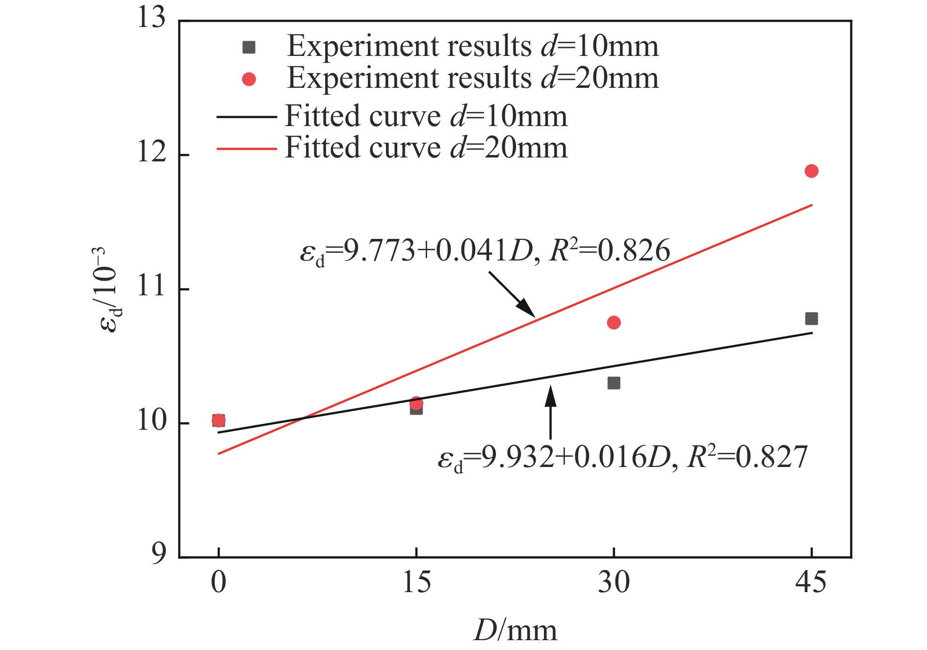
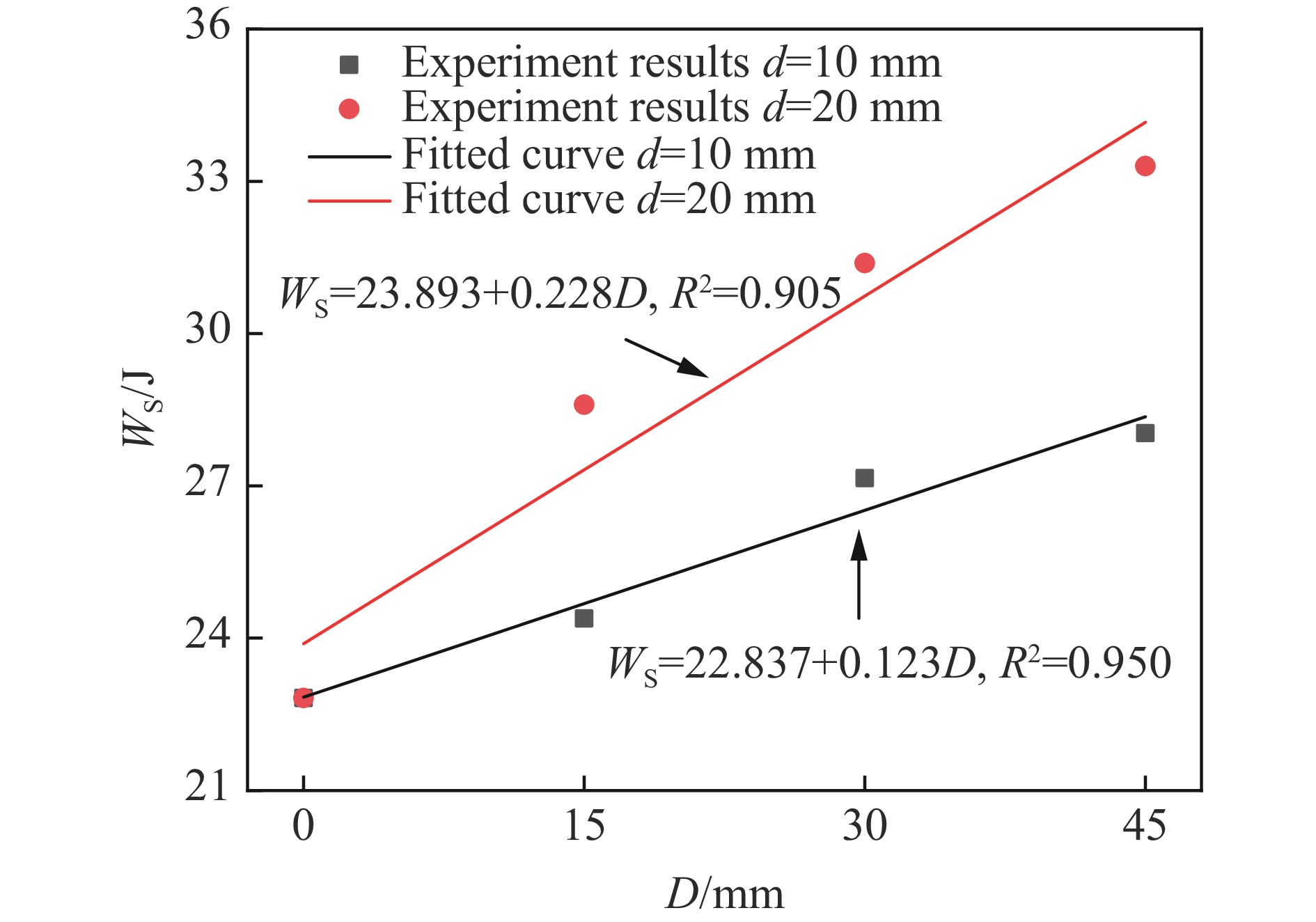
Cutting blasting is a crucial step in underground blasting driving. To investigate the influences of cutting cavity depth on subsequent rock breaking properties, driving sections with different cutting cavities depths were simplified as sandstone specimens with different depths of cavities. A series of dynamic compression tests were conducted using a 50 mm diameter Split Hopkinson pressure bar (SHPB) testing system. Then, the dynamic peak stresses, dynamic peak strains, energy dissipation characteristics, and fracture patterns of the specimens were analyzed as the cavity depth varied, and the field cutting blasting parameters were optimized accordingly. The results demonstrate significant trends for sandstone specimens with cavity diameters of 10 and 20 mm. As the cavity depth increases, the dynamic peak stress decreases by 17.69 % and 39.05 %, the dynamic peak strain increases by 7.58% and 18.56%, the dissipation energy increases by 22.87% and 45.92%, the dissipation energy density increases by 26.92% and 73.08%, respectively. And the specimens fragmentation size also gradually decreases with the extension of cavity depth. These findings indicate that increasing cutting cavity depth could reduce the rock mass resistance to failure, enhance its deformation capacity and energy utilization efficiency, and improve its fragmentation effects. When the cavity diameter is 20 mm, the dynamic mechanical properties and energy dissipation characteristics of the specimens change at a faster rate with the increase of cavity depth, and the fragmentation size is smaller. This indicates that increasing the cutting cavity diameter is also beneficial for rock breaking. The cutting blasting technique with inner-hole and outer-hole composite delays is adopted, which can increase the cavity depth and diameter to provide sufficient free surfaces for subsequent blasting process. This optimization achieved remarkable filed performance that increasing the cycle advance and hole utilization rate of the full-section blasting into 5.0 m and 96.1%, and ensuring uniform and reasonable rock fragmentation degree. The research findings not only effectively reveal the influences of cutting cavity depth on the full-section rock breaking effects, but also provide theoretical supports and practical references for the design optimization of actual cutting blasting projects.
Cutting blasting is a crucial step in underground blasting driving. To investigate the influences of cutting cavity depth on subsequent rock breaking properties, driving sections with different cutting cavities depths were simplified as sandstone specimens with different depths of cavities. A series of dynamic compression tests were conducted using a 50 mm diameter Split Hopkinson pressure bar (SHPB) testing system. Then, the dynamic peak stresses, dynamic peak strains, energy dissipation characteristics, and fracture patterns of the specimens were analyzed as the cavity depth varied, and the field cutting blasting parameters were optimized accordingly. The results demonstrate significant trends for sandstone specimens with cavity diameters of 10 and 20 mm. As the cavity depth increases, the dynamic peak stress decreases by 17.69 % and 39.05 %, the dynamic peak strain increases by 7.58% and 18.56%, the dissipation energy increases by 22.87% and 45.92%, the dissipation energy density increases by 26.92% and 73.08%, respectively. And the specimens fragmentation size also gradually decreases with the extension of cavity depth. These findings indicate that increasing cutting cavity depth could reduce the rock mass resistance to failure, enhance its deformation capacity and energy utilization efficiency, and improve its fragmentation effects. When the cavity diameter is 20 mm, the dynamic mechanical properties and energy dissipation characteristics of the specimens change at a faster rate with the increase of cavity depth, and the fragmentation size is smaller. This indicates that increasing the cutting cavity diameter is also beneficial for rock breaking. The cutting blasting technique with inner-hole and outer-hole composite delays is adopted, which can increase the cavity depth and diameter to provide sufficient free surfaces for subsequent blasting process. This optimization achieved remarkable filed performance that increasing the cycle advance and hole utilization rate of the full-section blasting into 5.0 m and 96.1%, and ensuring uniform and reasonable rock fragmentation degree. The research findings not only effectively reveal the influences of cutting cavity depth on the full-section rock breaking effects, but also provide theoretical supports and practical references for the design optimization of actual cutting blasting projects.

, Available online , doi: 10.11883/bzycj-2025-0234
Abstract:
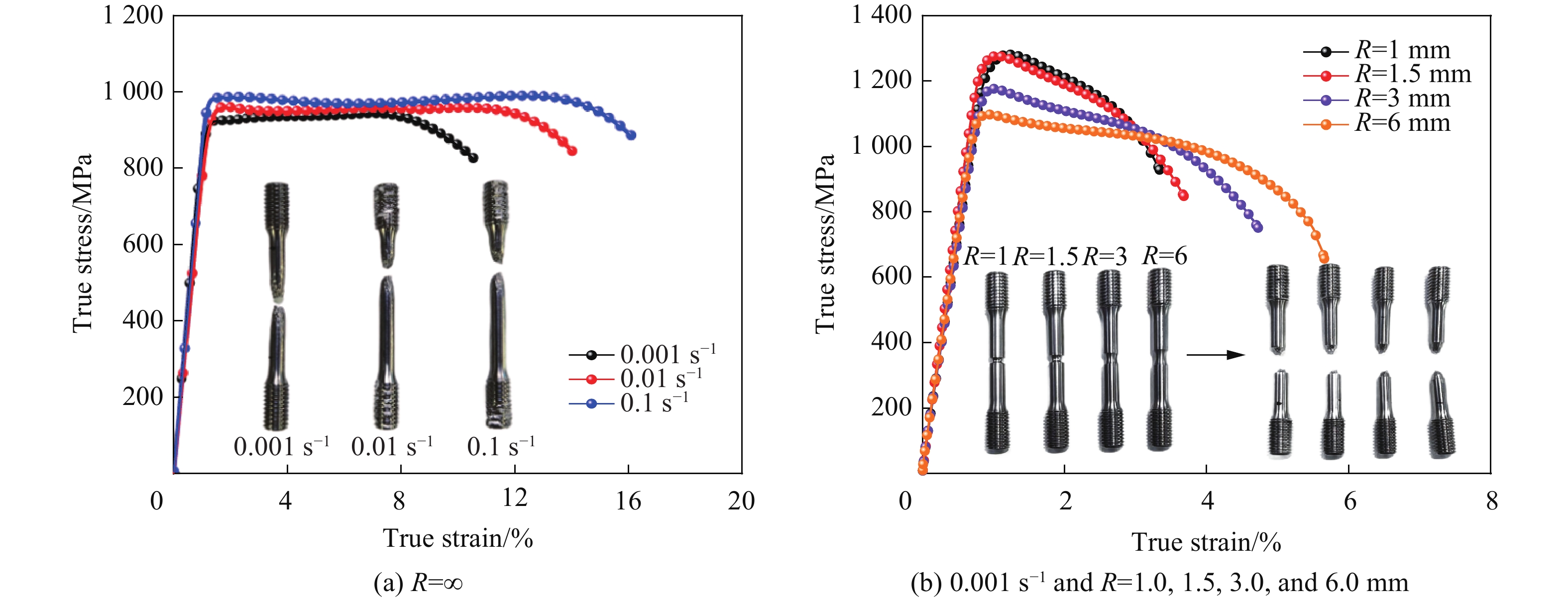
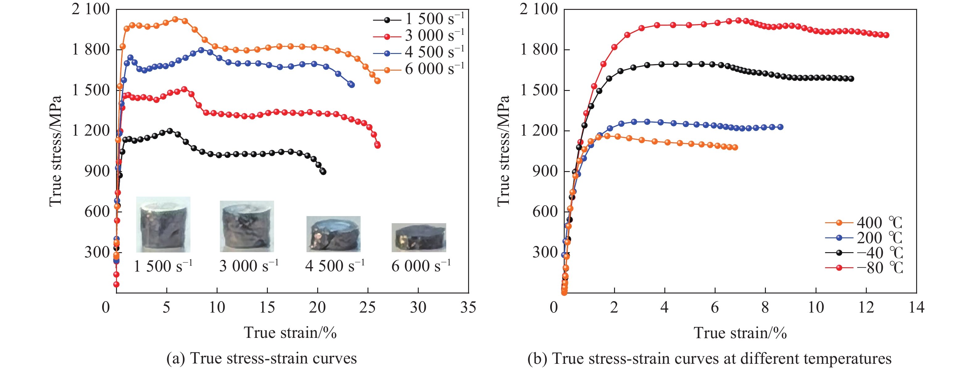
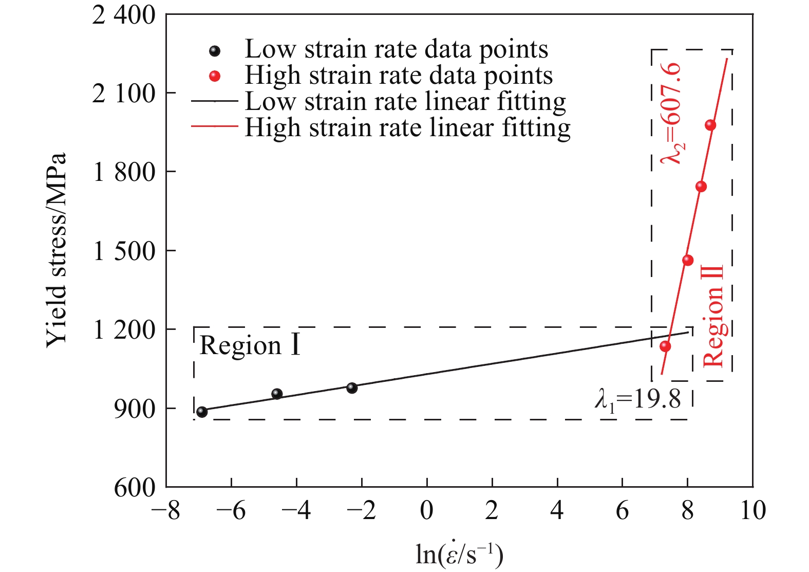
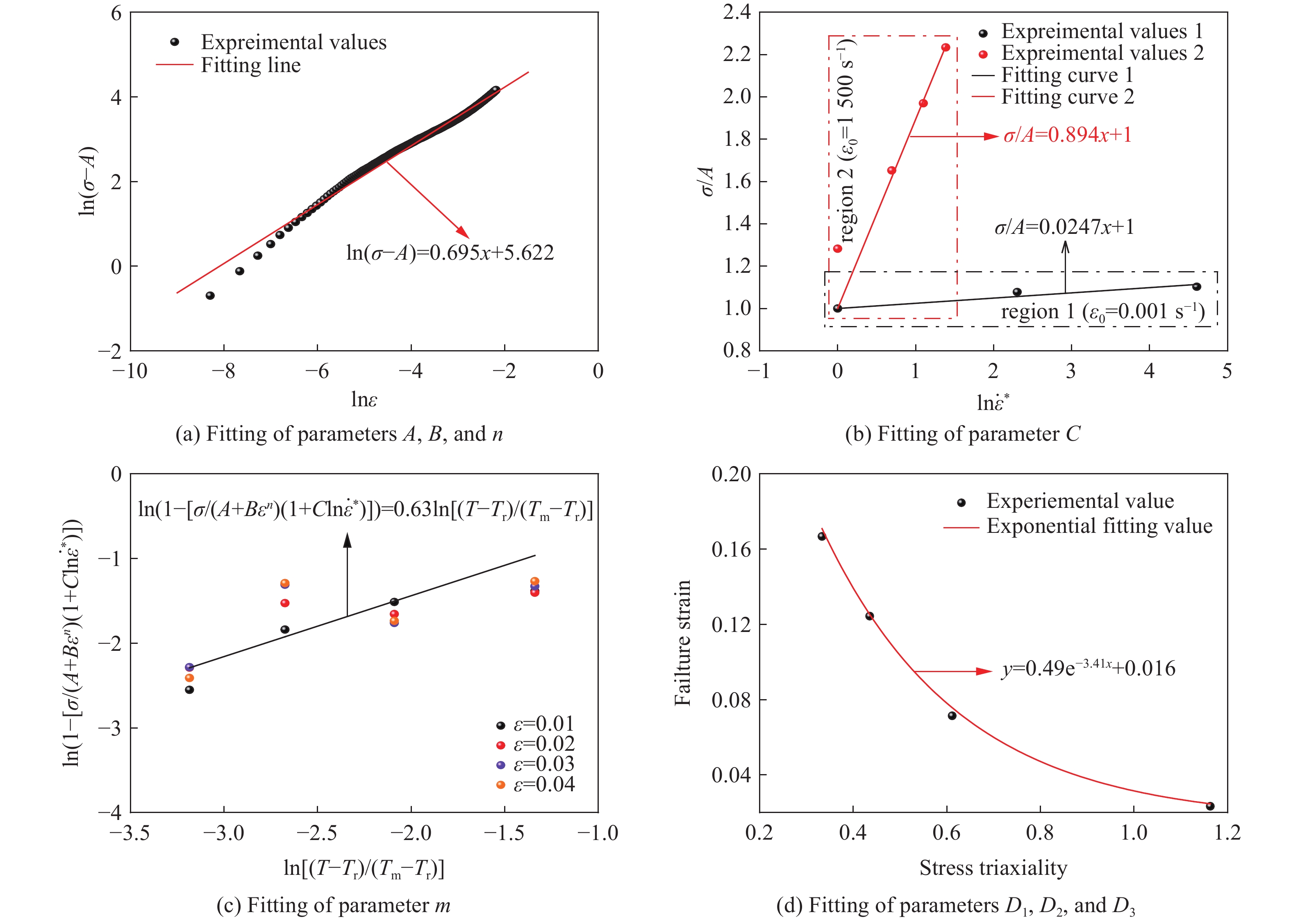
To overcome the limitations of traditional metallic materials regarding energy-release efficiency under high-velocity impact, this study designed and fabricated a novel single-phase body-centered cubic (BCC) structured lightweight refractory high-entropy alloy (Ti2Zr)1.5NbVAl0.5. The investigation employed a combined approach of multi-scale experimentation and numerical simulation. The as-cast microstructure was characterized, revealing a homogeneous composition with an average grain size of 336.7 μm. Quasi-static and dynamic mechanical tests were conducted to evaluate strength, plasticity, and strain-rate sensitivity, providing data to fit the Johnson-Cook constitutive and damage parameters. Direct ballistic experiments were conducted at impact velocities of 734, 950, and1375 m/s to analyze fragmentation behavior, temperature evolution, and energy release within a quasi-confined chamber. A coupled finite element method-smoothed particle hydrodynamics (FEM-SPH) numerical model was developed to simulate the penetration process, successfully replicating experimental temperature rises and fragmentation patterns. The results showed that the alloy possesses an excellent strength-plasticity synergy and remarkable strain-rate sensitivity, with yield strength increasing by 123% to 1977.3 MPa at 6000 s−1. Ballistic tests demonstrated that increased impact velocity intensified fragmentation and energy release, achieving a peak chamber temperature of 2124.15 K and extending the release duration to 12 ms at 1375 m/s. Microstructural analysis revealed that the energy release mechanism is governed by dislocation dynamics within adiabatic shear bands (ASBs). At lower impact velocities (e.g., 734 m/s), dynamic recrystallization in ASBs alleviates strain hardening. In contrast, at high velocities (e.g., 1375 m/s), suppressed cross-slip leads to dislocation saturation, local lattice instability, and ultimately severe fragmentation coupled with exothermic oxidation. The study concludes that (Ti2Zr)1.5NbVAl0.5 high-entropy alloy exhibits outstanding dynamic properties and controllable impact-induced energy release, primarily driven by velocity-dependent microstructural evolution in ASBs, demonstrating significant potential as a new-generation energetic structural material for extreme dynamic loading applications.
To overcome the limitations of traditional metallic materials regarding energy-release efficiency under high-velocity impact, this study designed and fabricated a novel single-phase body-centered cubic (BCC) structured lightweight refractory high-entropy alloy (Ti2Zr)1.5NbVAl0.5. The investigation employed a combined approach of multi-scale experimentation and numerical simulation. The as-cast microstructure was characterized, revealing a homogeneous composition with an average grain size of 336.7 μm. Quasi-static and dynamic mechanical tests were conducted to evaluate strength, plasticity, and strain-rate sensitivity, providing data to fit the Johnson-Cook constitutive and damage parameters. Direct ballistic experiments were conducted at impact velocities of 734, 950, and
, Available online , doi: 10.11883/bzycj-2025-0278
Abstract:
This study focuses on the scenario in which the secondary initiation charge column is positioned at the periphery of the cloud formed subsequent to the dispersion of the fuel-air explosive (FAE). It conducts in-depth research on the initiation margin of the cloud. A prototype filled with 12.5 kg of cloud-bursting agent was meticulously designed. The maximum radius of the cloud was precisely determined through a series of dispersion tests. A 1 kg HMX-based explosive was employed as the secondary initiation charge column. Through comprehensive experimental investigations, including high-speed and overpressure tests, the relationship between the distance of the charge column from the edge of the cloud and the initiation state of the cloud was established, and the distance threshold was accurately determined. Using the peak overpressure at the edge of the cloud as an index to measure the initiation margin, the threshold of the peak overpressure at the cloud edge that satisfies the initiation conditions of the cloud was investigated via empirical formulas and numerical simulations. The peak overpressure was further verified based on the critical energy flow criterion. The results indicate that placing a 1 kg HMX-based explosive at the periphery of the cloud can also trigger the cloud to detonate, provided that the distance from the cloud edge does not exceed 0.5 m. When the energy of the secondary initiation charge column is adequate to trigger stable detonation of the cloud, the location of the secondary initiation charge column exerts minimal influence on the detonation overpressure. To guarantee the initiation performance of the cloud, the peak overpressure at the edge of the cloud generated by the secondary initiation charge column should not be lower than 5 MPa. This study takes into account the stringent conditions for cloud initiation, and the research findings can offer support for the design of secondary initiation charge columns.
This study focuses on the scenario in which the secondary initiation charge column is positioned at the periphery of the cloud formed subsequent to the dispersion of the fuel-air explosive (FAE). It conducts in-depth research on the initiation margin of the cloud. A prototype filled with 12.5 kg of cloud-bursting agent was meticulously designed. The maximum radius of the cloud was precisely determined through a series of dispersion tests. A 1 kg HMX-based explosive was employed as the secondary initiation charge column. Through comprehensive experimental investigations, including high-speed and overpressure tests, the relationship between the distance of the charge column from the edge of the cloud and the initiation state of the cloud was established, and the distance threshold was accurately determined. Using the peak overpressure at the edge of the cloud as an index to measure the initiation margin, the threshold of the peak overpressure at the cloud edge that satisfies the initiation conditions of the cloud was investigated via empirical formulas and numerical simulations. The peak overpressure was further verified based on the critical energy flow criterion. The results indicate that placing a 1 kg HMX-based explosive at the periphery of the cloud can also trigger the cloud to detonate, provided that the distance from the cloud edge does not exceed 0.5 m. When the energy of the secondary initiation charge column is adequate to trigger stable detonation of the cloud, the location of the secondary initiation charge column exerts minimal influence on the detonation overpressure. To guarantee the initiation performance of the cloud, the peak overpressure at the edge of the cloud generated by the secondary initiation charge column should not be lower than 5 MPa. This study takes into account the stringent conditions for cloud initiation, and the research findings can offer support for the design of secondary initiation charge columns.
, Available online , doi: 10.11883/bzycj-2025-0225
Abstract:
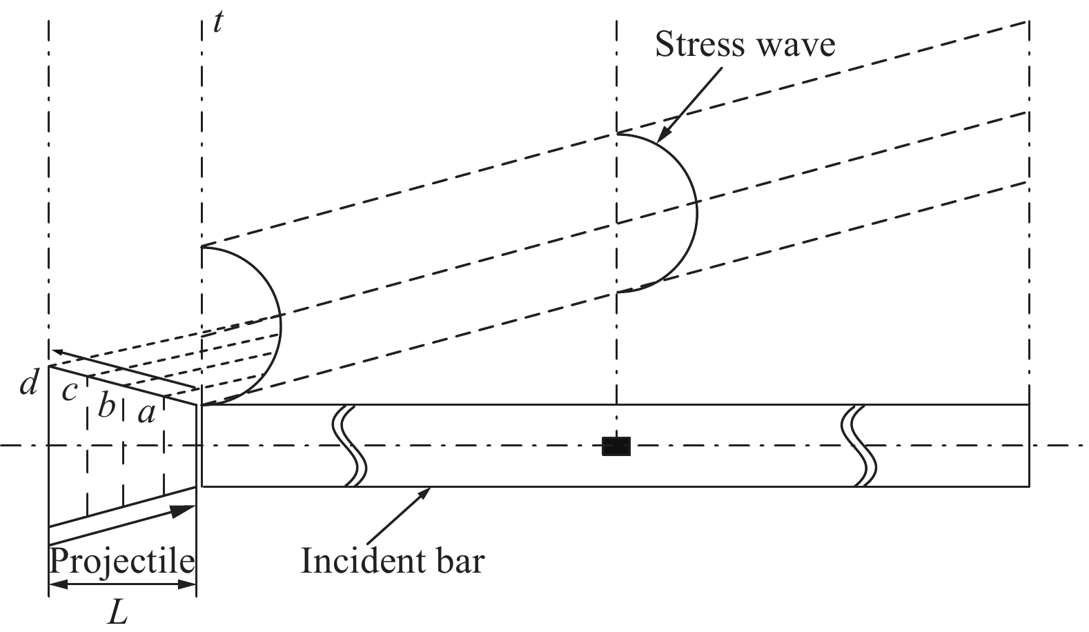
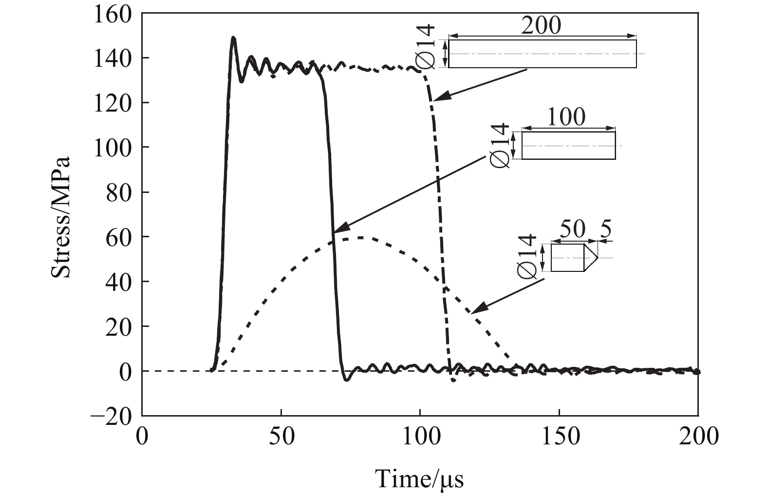
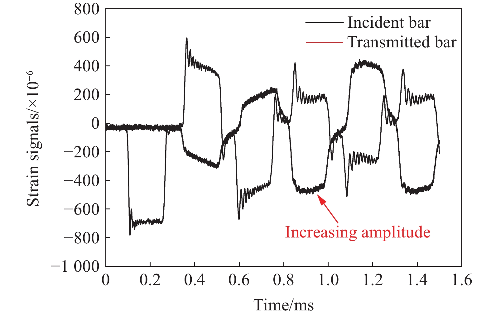
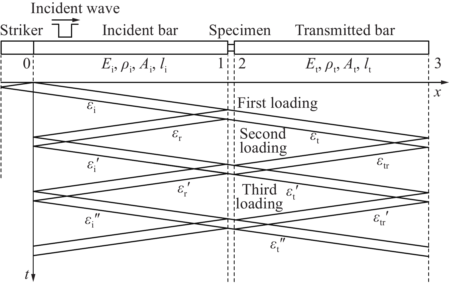
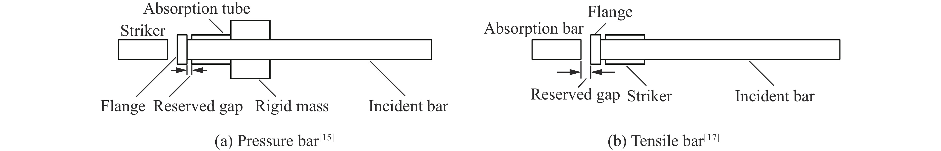
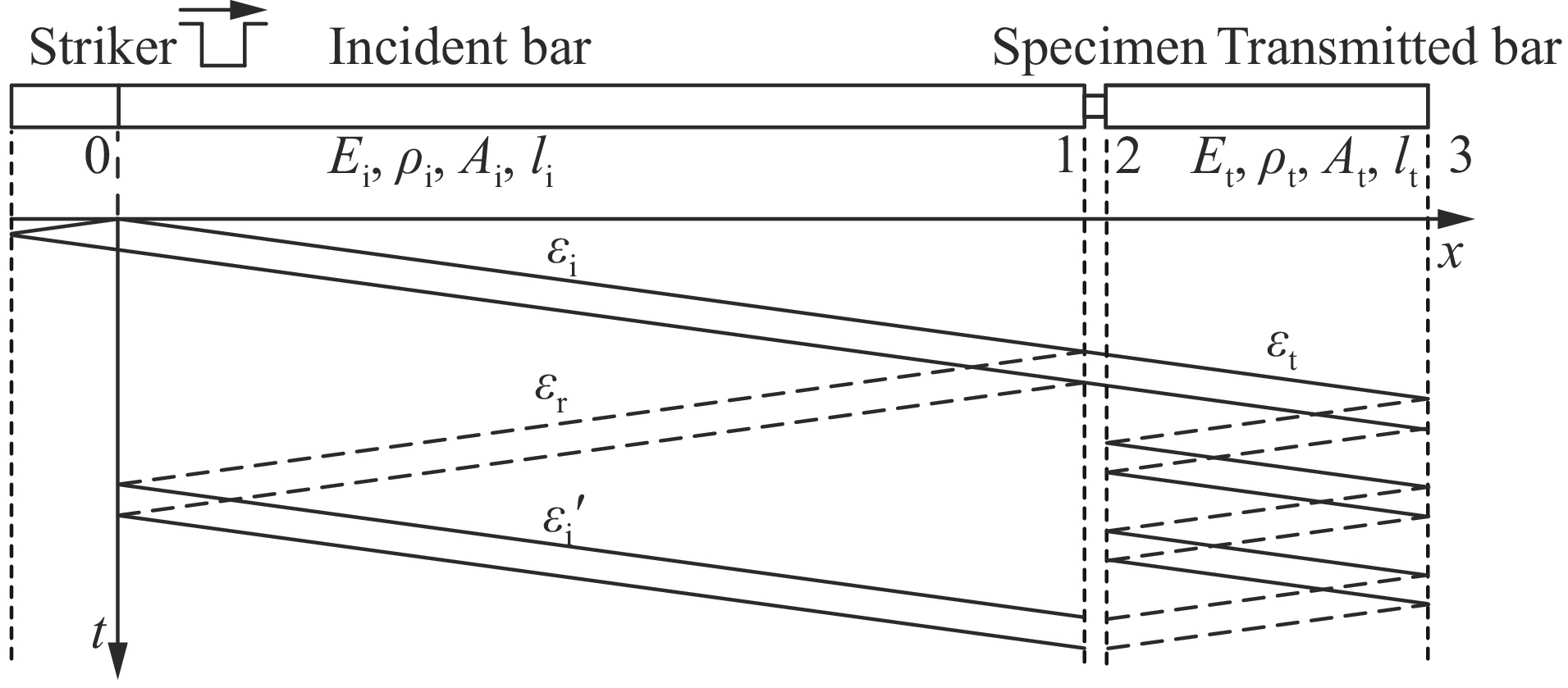
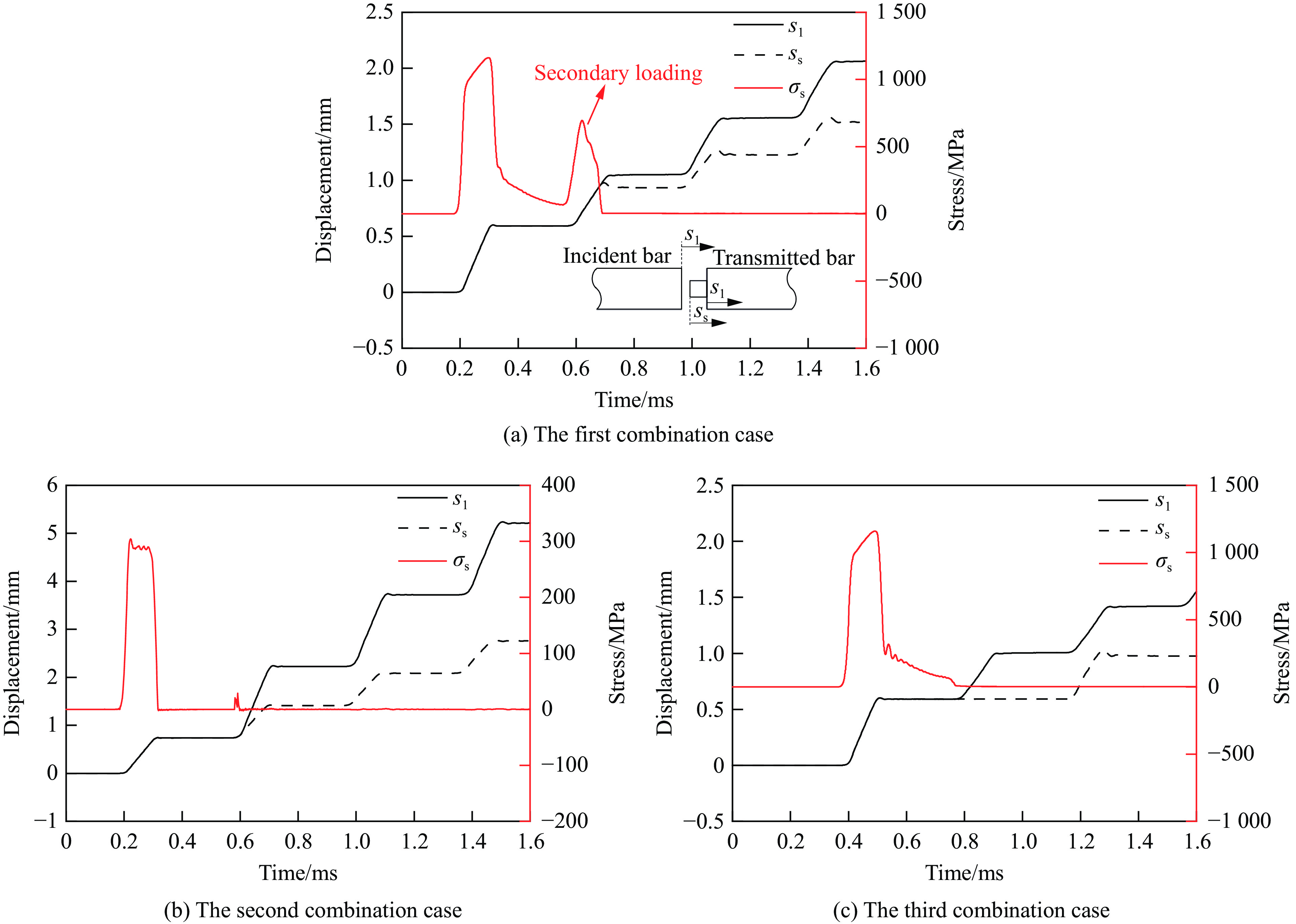
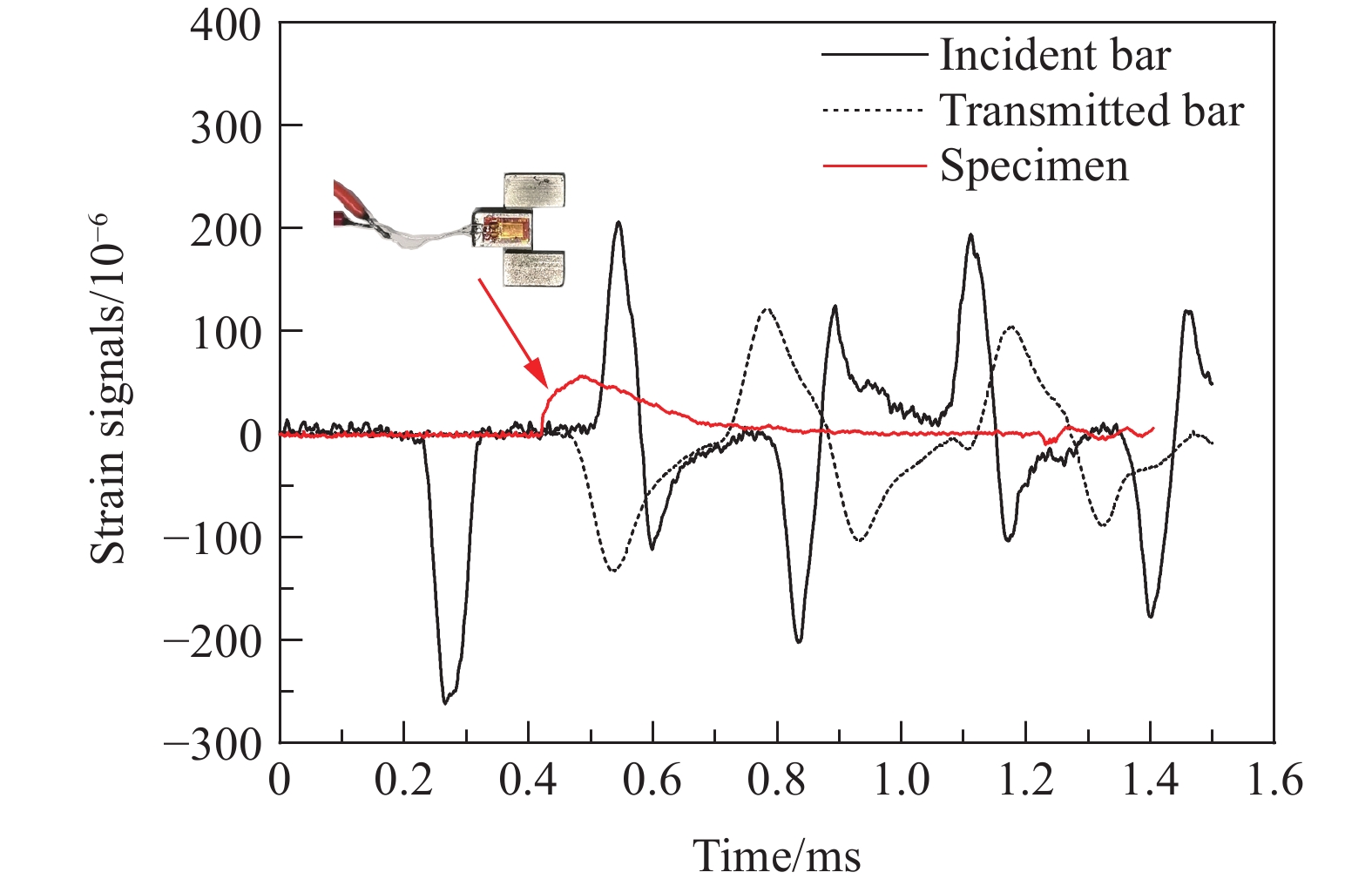
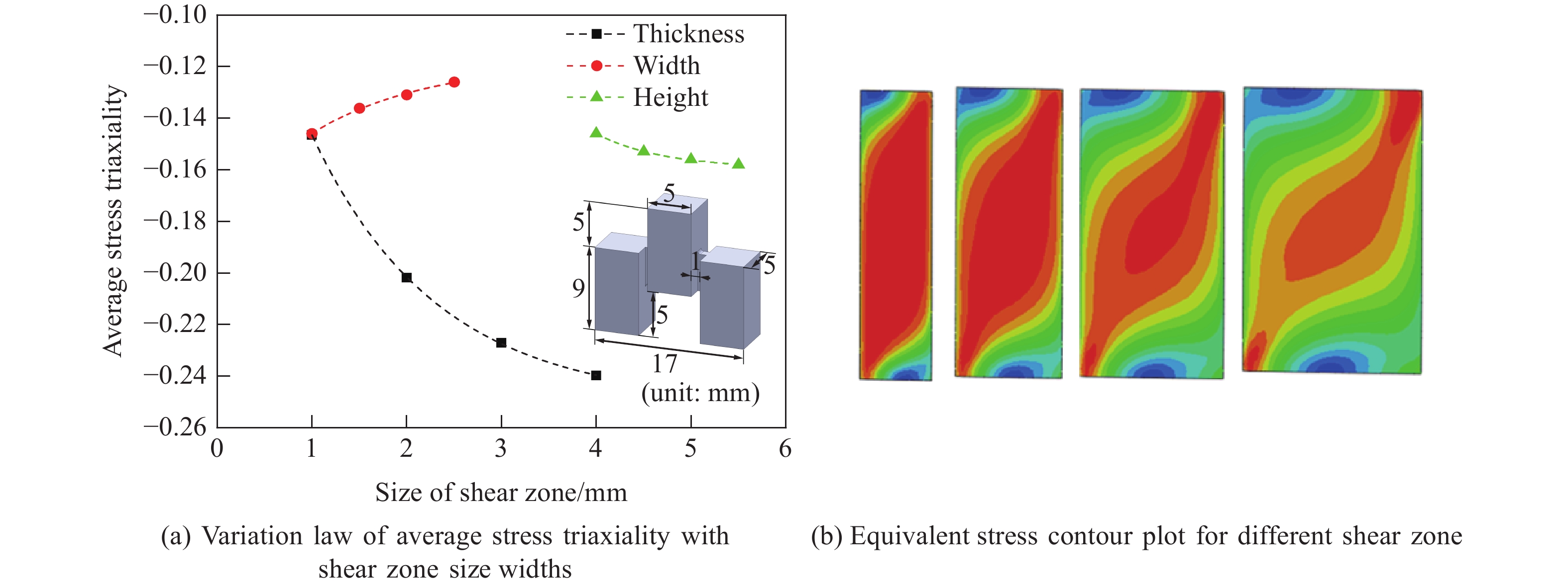
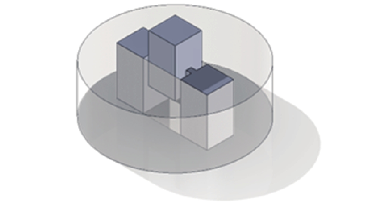
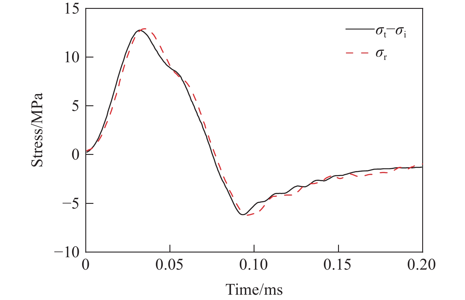
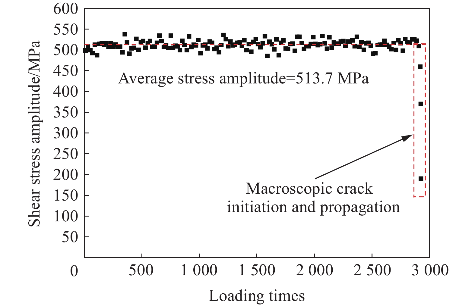
In both national defense and civilian applications, various equipment and structural components are frequently subjected to intermittent, high loading rates, and repetitive severe impact loads, which are referred to as repeated impacts or impact fatigue. To study the impact fatigue behavior of equipment or structures, it is necessary to first establish reliable impact fatigue testing techniques or methodologies. Therefore, the conventional Hopkinson bar impact loading system was modified and enhanced, and the stress wave propagation characteristics in the loading bar, specimen, and associated fixtures under successive impacts were analyzed in detail. The method for controlling the amplitude, width, and waveform configuration of the impact loading pulse applied to the specimen was systematically analyzed. In addition, a theoretical analysis was conducted on the principle of achieving single pulse loading in impact fatigue testing. Effective control of the amplitude, pulse width, and the stress wave pulse configuration of the loading wave is realized by optimizing and modifying the impact velocity, length, and geometric shape of the projectile. Consequently, a simple and efficient single pulse loading method suitable for impact fatigue testing was proposed. The core principle involves designing the length and material parameters of the loading bar such that the end surfaces of the specimen and the bar coordinate and then separate, thereby preventing irregular and random secondary or multiple loadings caused by reflected stress waves. This design ensures that each individual impact in a continuous impact sequence results in a single loading on the specimen. The effectiveness and feasibility of the proposed impact fatigue testing technique have been verified through a combination of numerical simulations and experimental investigations. Additionally, a dedicated loading fixture for shear-type impact fatigue was developed, enabling the acquisition of the shear impact fatigue stress-life curve of TC4 titanium alloy, thus demonstrating the method’s applicability to complex loading modes.
In both national defense and civilian applications, various equipment and structural components are frequently subjected to intermittent, high loading rates, and repetitive severe impact loads, which are referred to as repeated impacts or impact fatigue. To study the impact fatigue behavior of equipment or structures, it is necessary to first establish reliable impact fatigue testing techniques or methodologies. Therefore, the conventional Hopkinson bar impact loading system was modified and enhanced, and the stress wave propagation characteristics in the loading bar, specimen, and associated fixtures under successive impacts were analyzed in detail. The method for controlling the amplitude, width, and waveform configuration of the impact loading pulse applied to the specimen was systematically analyzed. In addition, a theoretical analysis was conducted on the principle of achieving single pulse loading in impact fatigue testing. Effective control of the amplitude, pulse width, and the stress wave pulse configuration of the loading wave is realized by optimizing and modifying the impact velocity, length, and geometric shape of the projectile. Consequently, a simple and efficient single pulse loading method suitable for impact fatigue testing was proposed. The core principle involves designing the length and material parameters of the loading bar such that the end surfaces of the specimen and the bar coordinate and then separate, thereby preventing irregular and random secondary or multiple loadings caused by reflected stress waves. This design ensures that each individual impact in a continuous impact sequence results in a single loading on the specimen. The effectiveness and feasibility of the proposed impact fatigue testing technique have been verified through a combination of numerical simulations and experimental investigations. Additionally, a dedicated loading fixture for shear-type impact fatigue was developed, enabling the acquisition of the shear impact fatigue stress-life curve of TC4 titanium alloy, thus demonstrating the method’s applicability to complex loading modes.

, Available online , doi: 10.11883/bzycj-2025-0362
Abstract:
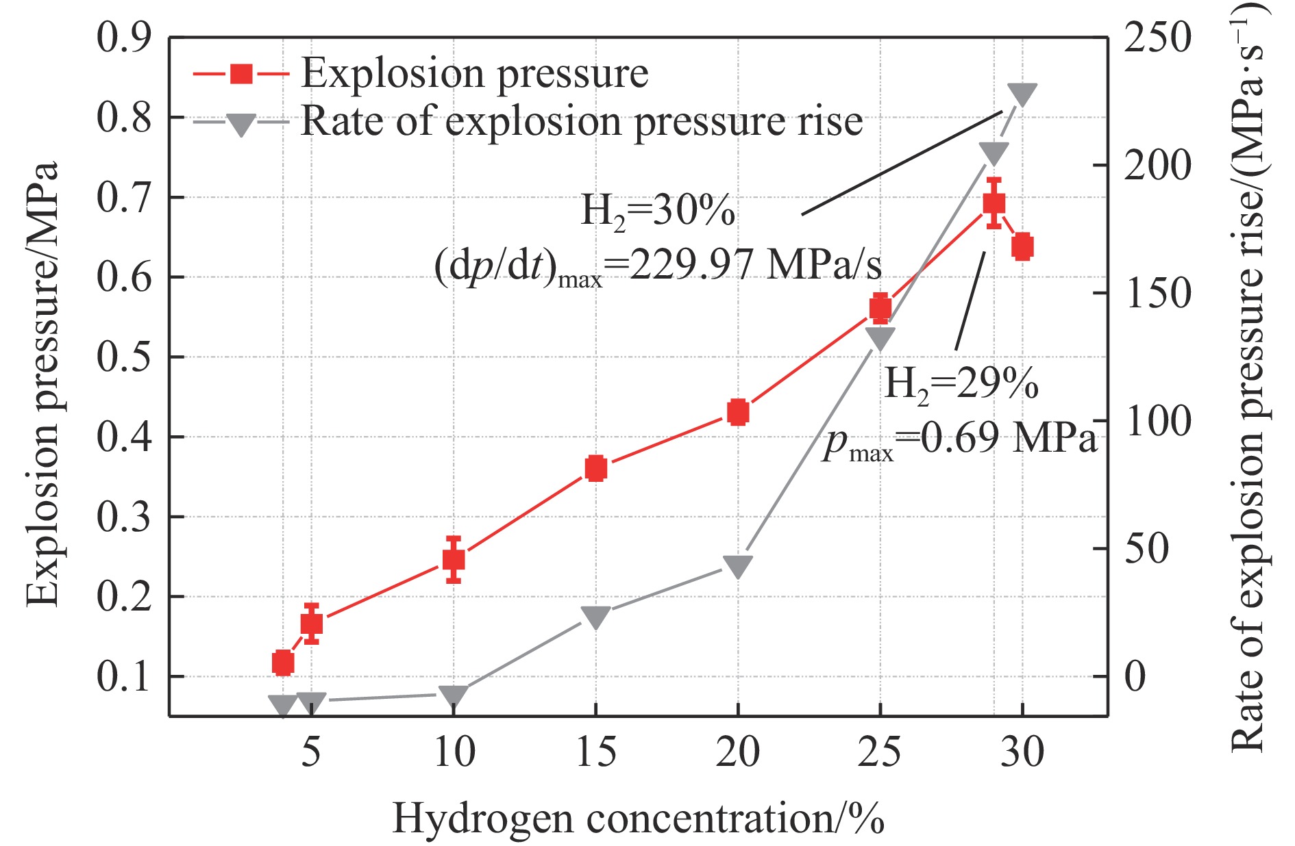
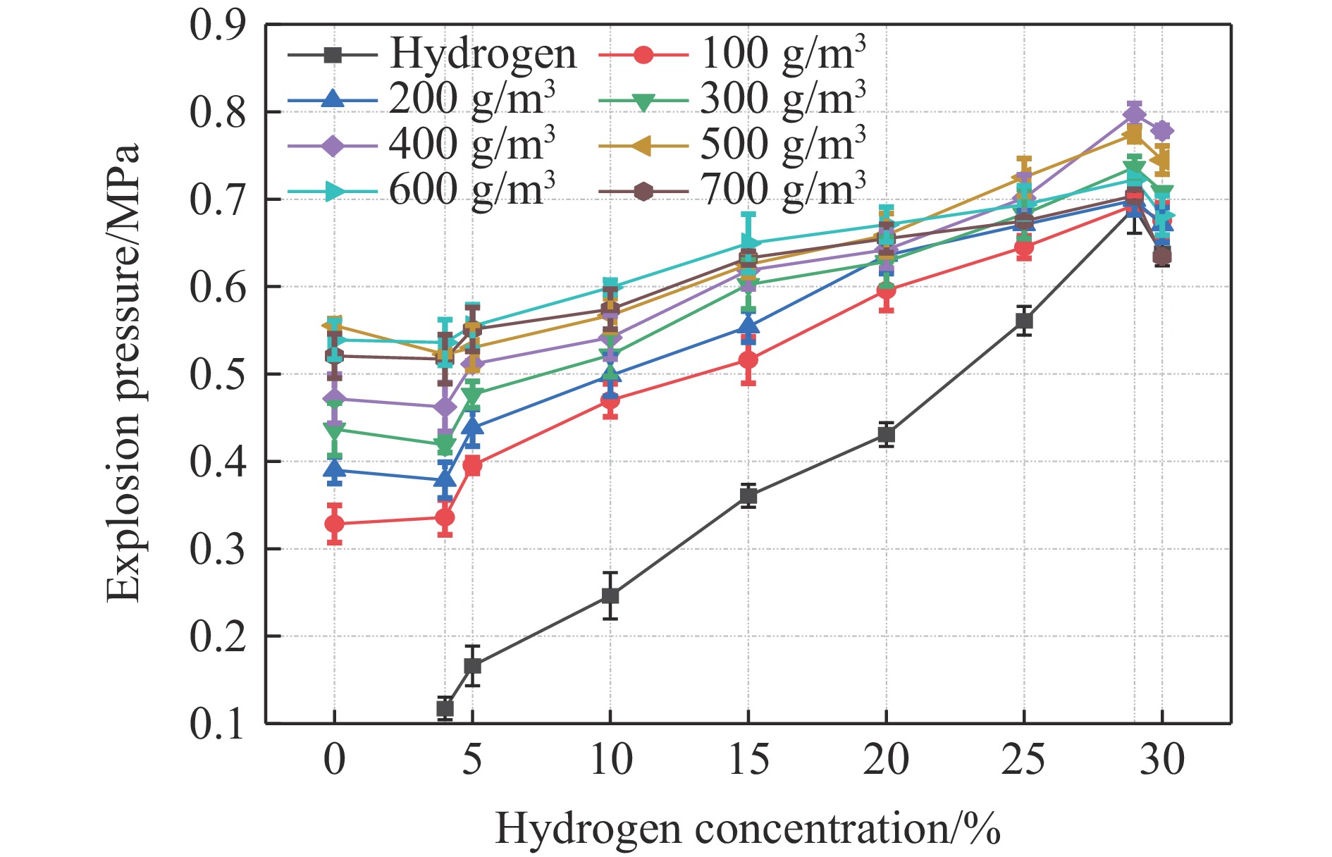
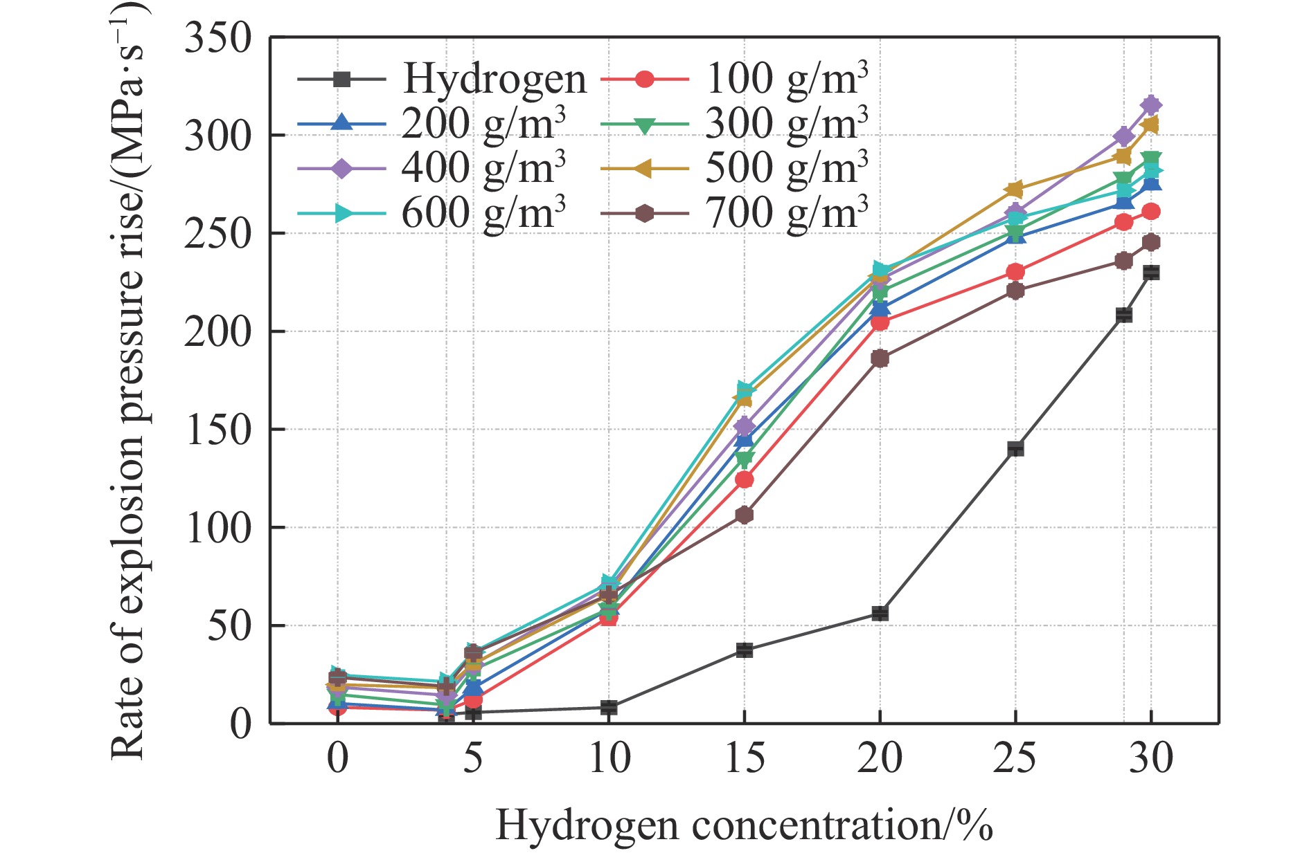
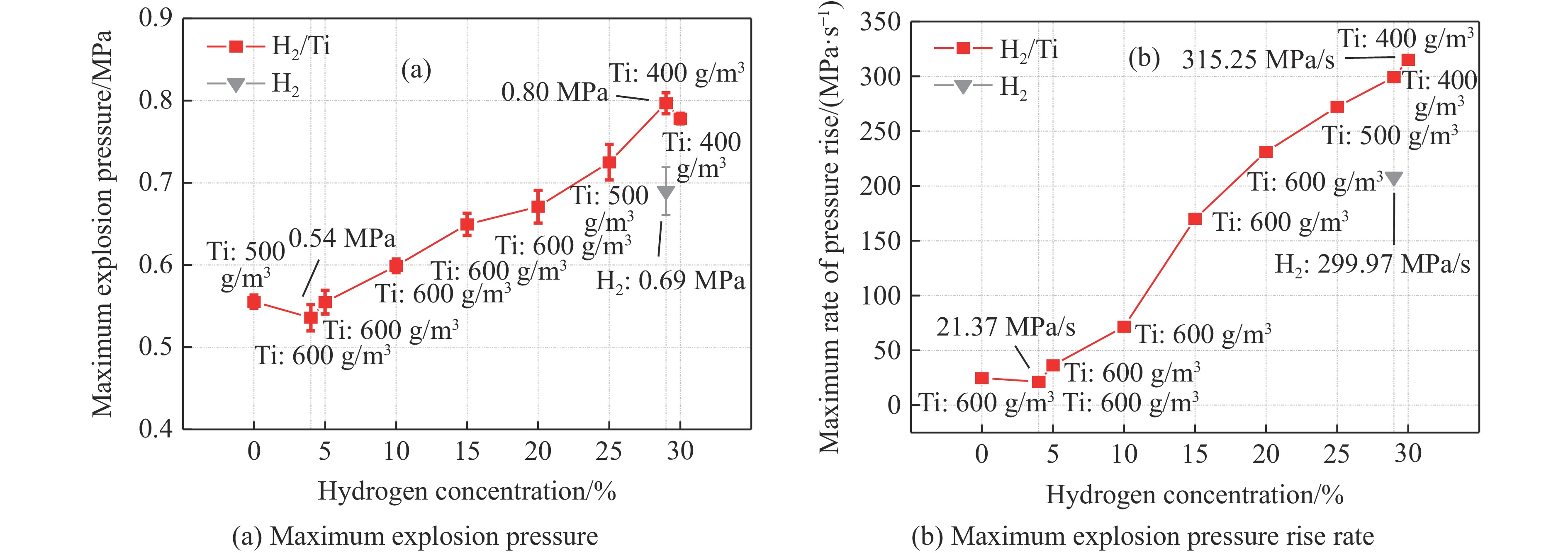
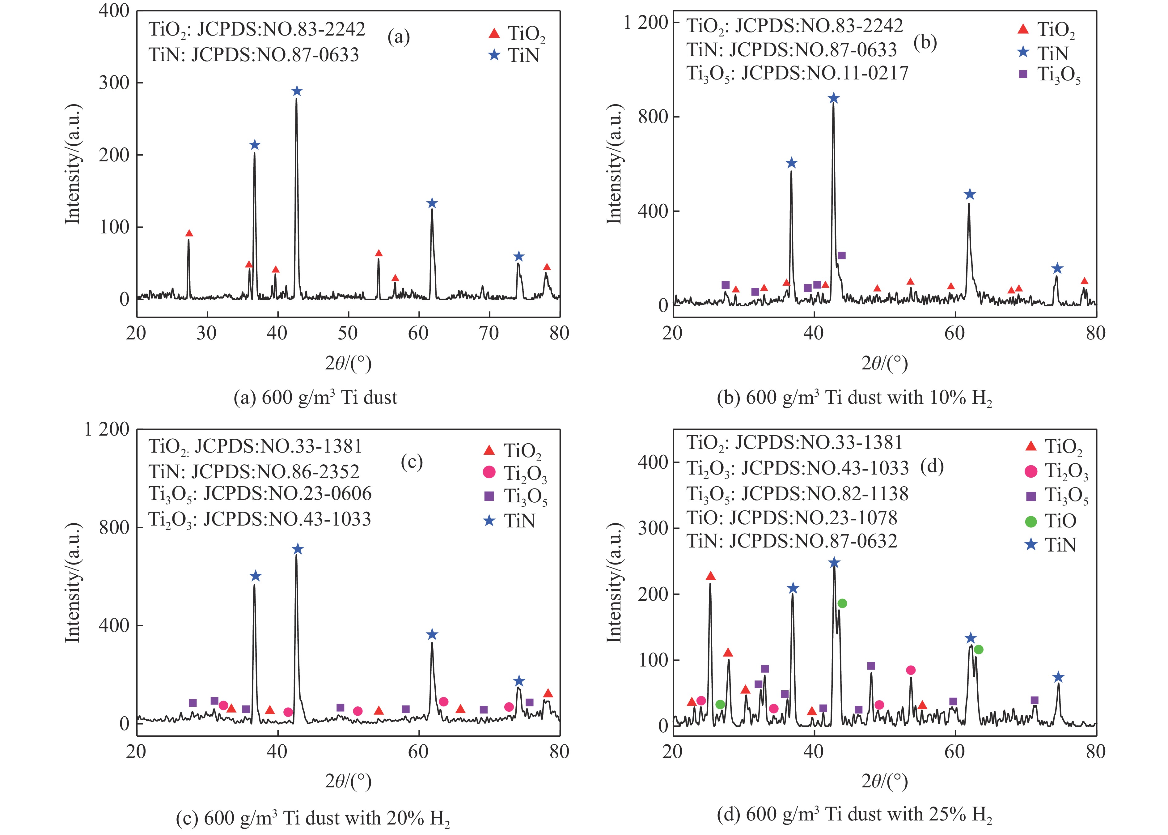
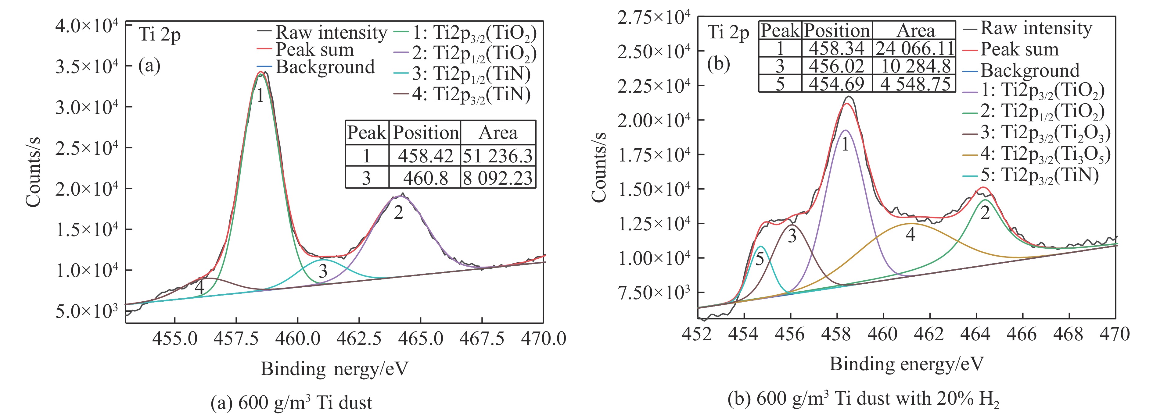
The advancement of titanium-based solid-state hydrogen storage technologies and titanium manufacturing processes inherently involves the formation of hydrogen/titanium dust hybrid mixtures, which present substantial explosion hazards. To investigate the explosion behavior of such two-phase systems, this study systematically examined the variation patterns of explosion intensity parameters in hydrogen/titanium dust hybrid systems using a standardized 20 L spherical explosion vessel. The experimental matrix covers hydrogen volume fraction ranging from 0% to 30% and titanium dust mass concentrations from 100 to 700 g/m3. Specifically, titanium dust concentrations were tested at seven discrete levels (100, 200, 300, 400, 500, 600, and 700 g/m3), while hydrogen volume fractions were selected at eight critical values (4%, 5%, 10%, 15%, 20%, 25%, 29%, and 30%). Dynamic parameters, including explosion pressure and rate of explosion pressure rise, were synchronously recorded. Furthermore, the phase composition and surface chemical states of explosion residues were characterized using X-ray diffraction (XRD) and X-ray photoelectron spectroscopy (XPS). This integrated approach provides in-depth insights into the macroscopic evolution of explosion intensity with varying gas-solid ratios and elucidates the underlying microscopic reaction mechanisms. Experimental results demonstrate that hydrogen volume fraction critically modulates explosion severity. The explosion pressure exhibits a characteristic three-stage dependence on hydrogen volume fraction: it initially decreases, reaching a minimum at 4% H2, subsequently increases to a maximum at 29% H2, and finally declines at higher volume fractions. Correspondingly, the maximum rate of pressure rise rate decreases to its lowest value at 4% H2 before increasing continuously up to 30% H2. The maximum explosion pressure shows an analogous trend, peaking at 29% H2 after an initial reduction, while the maximum rate of pressure rise reaches its minimum at 4% H2 and peaks at 30% H2. Residue analysis indicates that at low hydrogen volume fraction (<4%), incomplete oxidation of titanium predominates, thereby reducing explosion intensity. Beyond the critical threshold of 4% H2, hydrogen self-combustion promotes titanium-nitrogen reactions and facilitates the transition from heterogeneous to homogeneous combustion, significantly enhancing explosion severity. This investigation provides fundamental insights into the explosion dynamics of hydrogen/titanium dust mixtures and delivers essential parameters for risk assessment and safety mitigation in related industrial applications.
The advancement of titanium-based solid-state hydrogen storage technologies and titanium manufacturing processes inherently involves the formation of hydrogen/titanium dust hybrid mixtures, which present substantial explosion hazards. To investigate the explosion behavior of such two-phase systems, this study systematically examined the variation patterns of explosion intensity parameters in hydrogen/titanium dust hybrid systems using a standardized 20 L spherical explosion vessel. The experimental matrix covers hydrogen volume fraction ranging from 0% to 30% and titanium dust mass concentrations from 100 to 700 g/m3. Specifically, titanium dust concentrations were tested at seven discrete levels (100, 200, 300, 400, 500, 600, and 700 g/m3), while hydrogen volume fractions were selected at eight critical values (4%, 5%, 10%, 15%, 20%, 25%, 29%, and 30%). Dynamic parameters, including explosion pressure and rate of explosion pressure rise, were synchronously recorded. Furthermore, the phase composition and surface chemical states of explosion residues were characterized using X-ray diffraction (XRD) and X-ray photoelectron spectroscopy (XPS). This integrated approach provides in-depth insights into the macroscopic evolution of explosion intensity with varying gas-solid ratios and elucidates the underlying microscopic reaction mechanisms. Experimental results demonstrate that hydrogen volume fraction critically modulates explosion severity. The explosion pressure exhibits a characteristic three-stage dependence on hydrogen volume fraction: it initially decreases, reaching a minimum at 4% H2, subsequently increases to a maximum at 29% H2, and finally declines at higher volume fractions. Correspondingly, the maximum rate of pressure rise rate decreases to its lowest value at 4% H2 before increasing continuously up to 30% H2. The maximum explosion pressure shows an analogous trend, peaking at 29% H2 after an initial reduction, while the maximum rate of pressure rise reaches its minimum at 4% H2 and peaks at 30% H2. Residue analysis indicates that at low hydrogen volume fraction (<4%), incomplete oxidation of titanium predominates, thereby reducing explosion intensity. Beyond the critical threshold of 4% H2, hydrogen self-combustion promotes titanium-nitrogen reactions and facilitates the transition from heterogeneous to homogeneous combustion, significantly enhancing explosion severity. This investigation provides fundamental insights into the explosion dynamics of hydrogen/titanium dust mixtures and delivers essential parameters for risk assessment and safety mitigation in related industrial applications.
, Available online , doi: 10.11883/bzycj-2025-0273
Abstract:
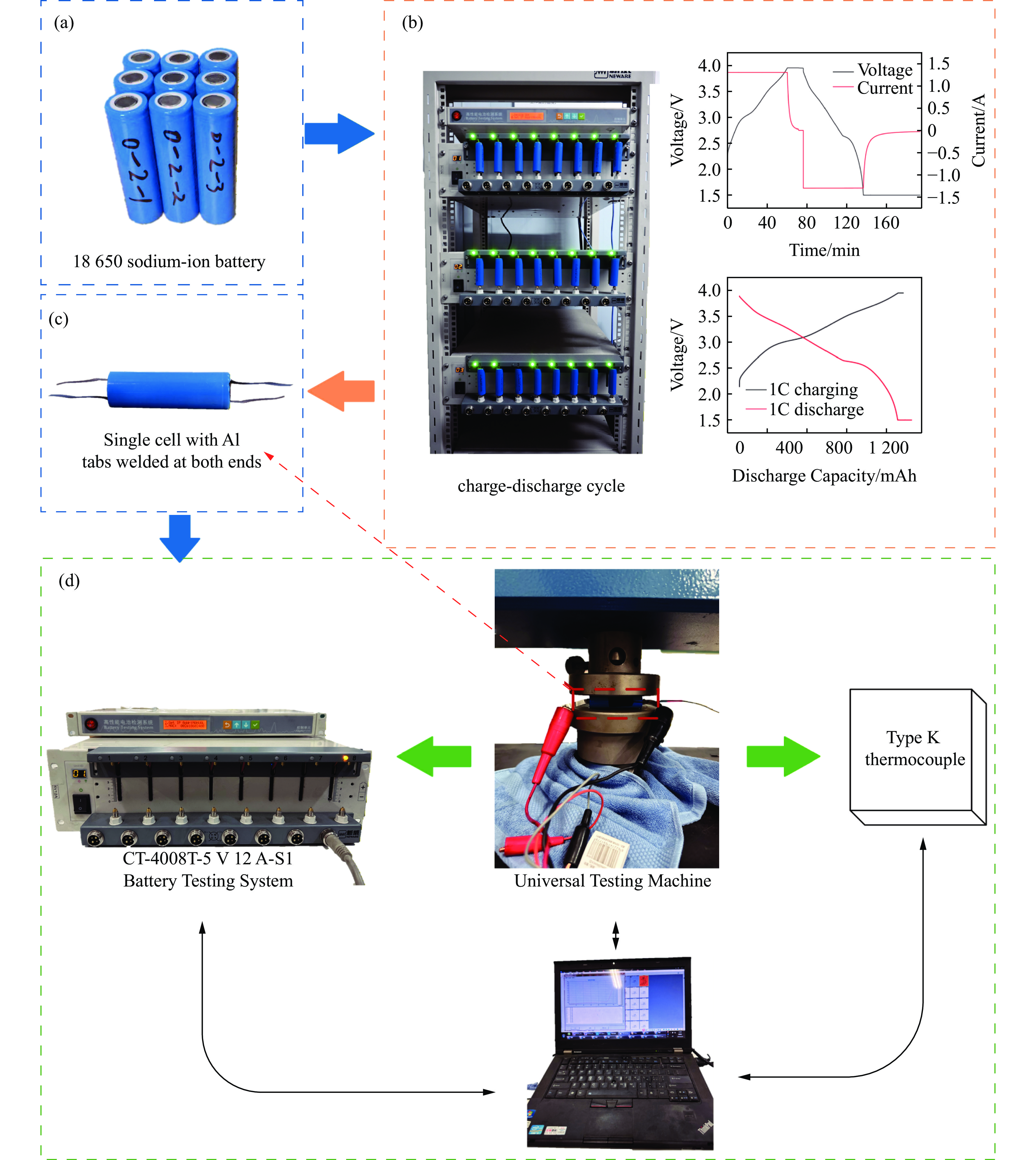
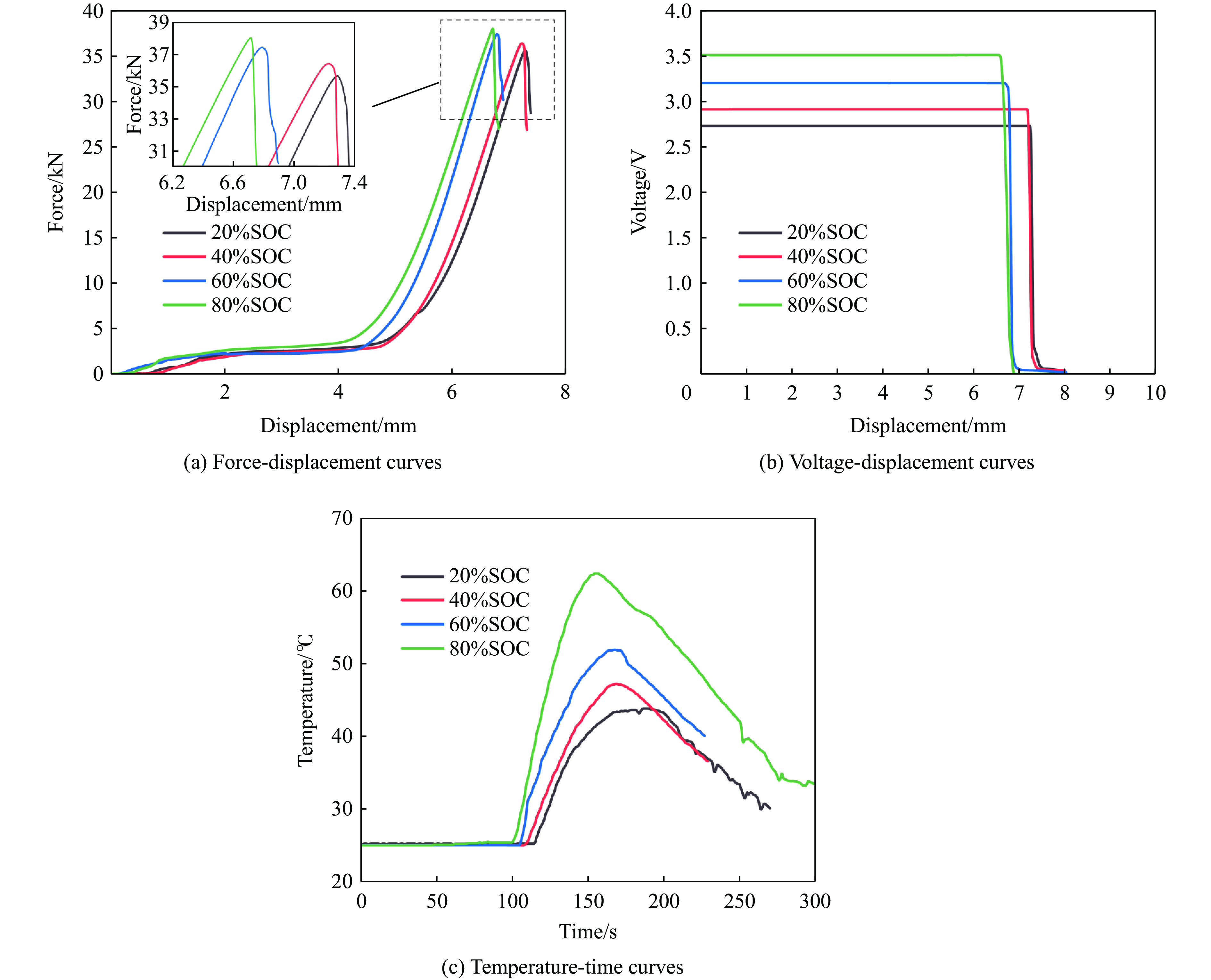
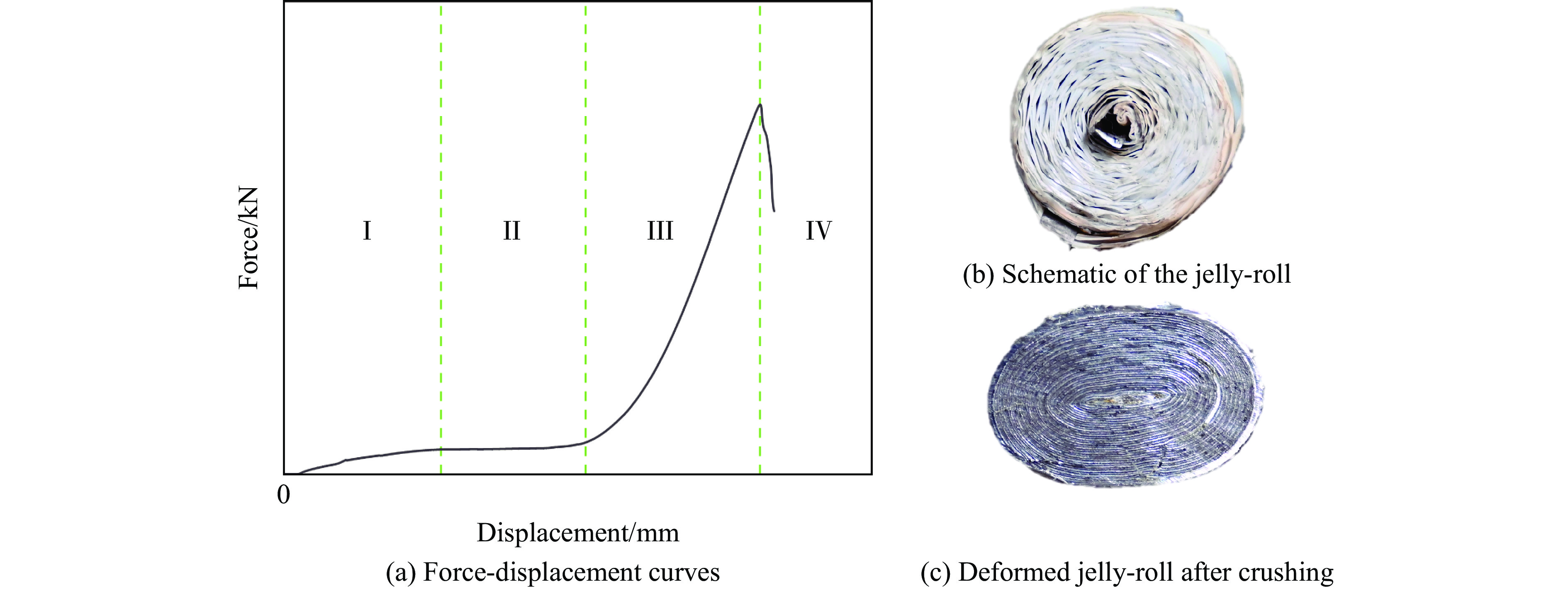
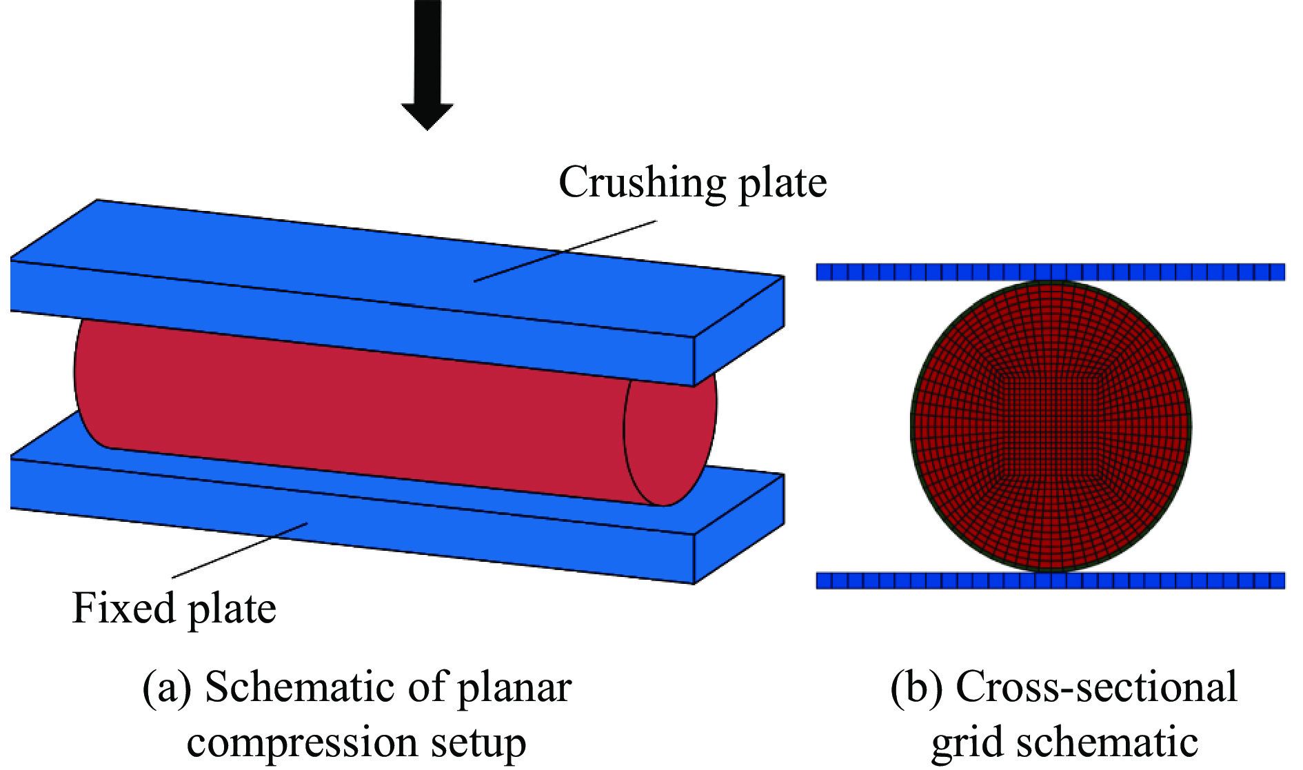
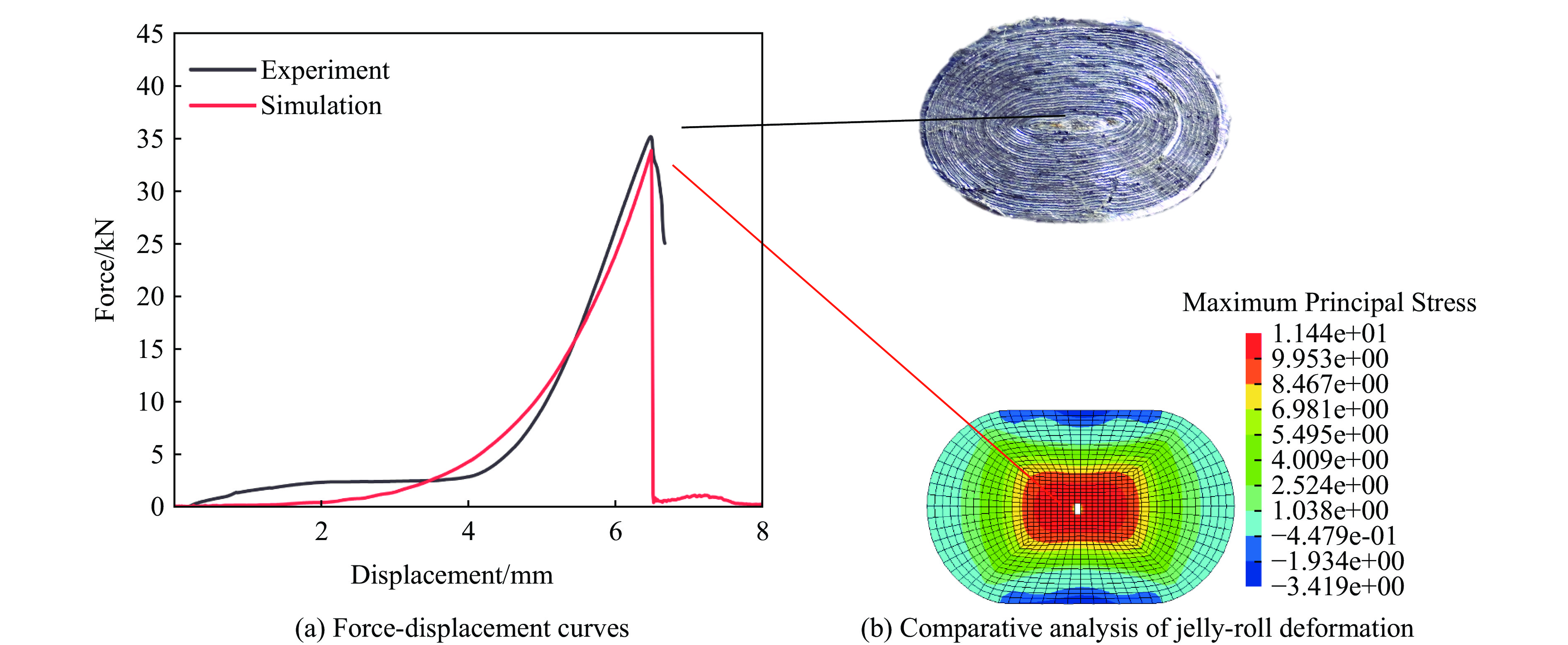
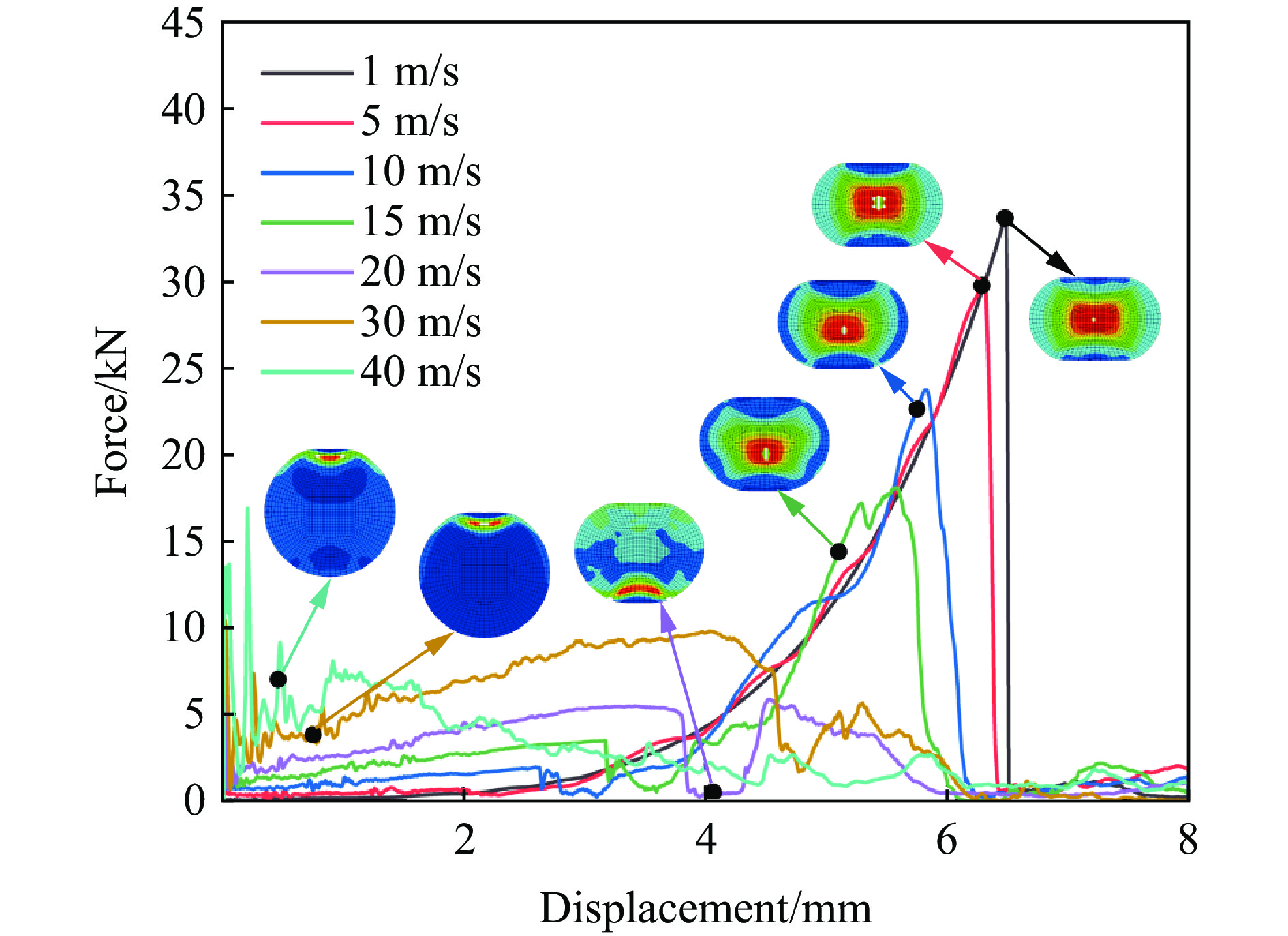
Sodium-ion batteries (SIBs) have emerged as a promising candidate for energy storage applications owing to their material abundance and cost-effectiveness; however, safety issues under mechanical abuse conditions remain insufficiently understood. This study systematically investigates the failure mechanisms of commercial18650 sodium-ion batteries subjected to radial compression by integrating experimental and numerical approaches. Experiments were conducted using an electronic universal testing machine to characterize the mechanical–electrical–thermal responses at different compression speeds and states of charge (SOC), with synchronous measurements of load, voltage, and temperature. A homogenized finite element model was established to simulate the dynamic crushing behavior at impact velocities ranging from 1 to 35 m/s. The failure mechanisms were interpreted based on stress wave theory, and the failure criteria were calibrated using the experimental results. The results indicate that under quasi-static loading, the battery exhibits a four-stage deformation process, in which the peak load coincides with the onset of failure. With increasing compression velocity, both the peak load and the failure displacement increase, while the temperature rise of batteries at 0% SOC is only weakly affected. In contrast, higher SOC significantly intensifies the temperature rise and advances the occurrence of failure. Under dynamic impact conditions, the failure displacement decreases with increasing impact velocity and shows a pronounced reduction beyond 20 m/s, whereas the load–displacement curve exhibits a distinct plateau at high velocities. The crack initiation location displays a strong dependence on impact velocity: it originates in the central region at low velocities (<15 m/s), shifts to the bottom at approximately 20 m/s, and moves to the impact end when the velocity exceeds 30 m/s. This transition is mainly governed by the propagation, reflection, and superposition of stress waves. Overall, the results indicate that failure of sodium-ion batteries is triggered by structural instability leading to internal short circuits. The SOC primarily controls the thermal response under low-speed compression, whereas stress wave effects dominate the failure behavior at high impact velocities. The proposed model demonstrates good predictive capability for the macroscopic mechanical response and provides valuable insights for the safety design of sodium-ion batteries.
Sodium-ion batteries (SIBs) have emerged as a promising candidate for energy storage applications owing to their material abundance and cost-effectiveness; however, safety issues under mechanical abuse conditions remain insufficiently understood. This study systematically investigates the failure mechanisms of commercial


, Available online , doi: 10.11883/bzycj-2025-0102
Abstract:
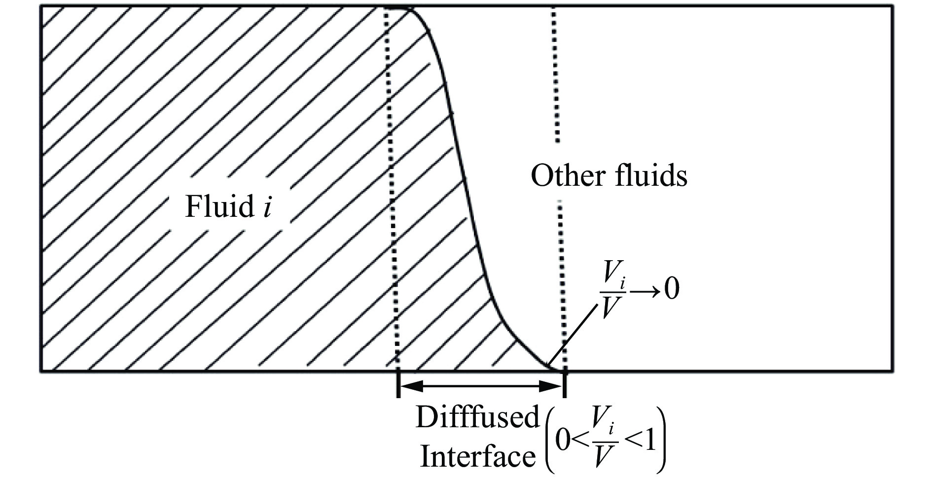
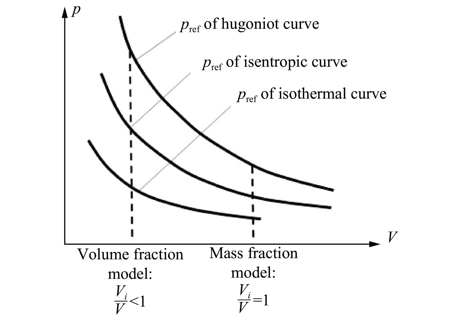
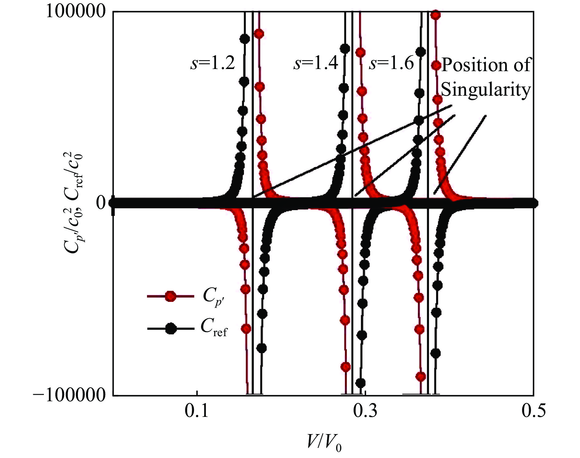
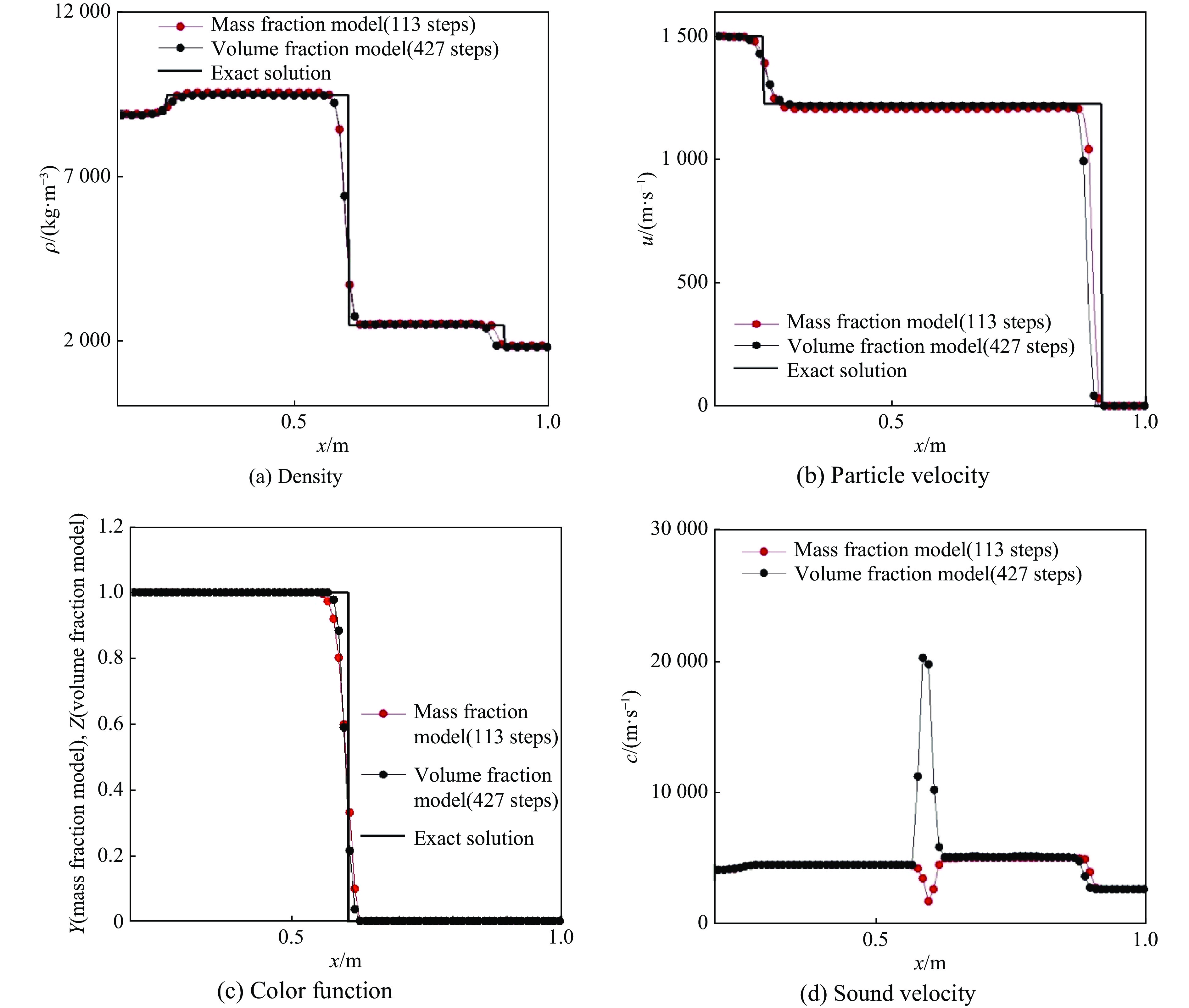
The Mie-Grüneisen mixture model is conveniently used in the multi-component problem with Mie-Grüneisen EOS (equation of states). In the Mie-Grüneisen EOS, the isentropic and Hugoniot curves are two typical reference states curves. However, the curves of these two reference states contain singularity points and cause difficulty when the interface is treated by volume fraction, which is accustomed used as a color function in traditional model. The difficulty lies in that the volume fraction model produces fragments of fluid volumes near the interface due to its diffused style, these volume fragments may encounter the singularity points and make the sound velocity abnormally high at the interface in some isentropic reference curves. On the other side, the singularity points may cause the sound velocity negative for some Hugoniot reference states and interrupt the calculation. To avoid volumes fragments near the interface area, the volume fraction is replaced by mass fraction, and the relative volume is defined by the reciprocal of proportional density of fluid component. This definition makes the relative volume no less than which of fluids mixture. Thanks to the reconstructed relative volume, the sound velocity forms a trough shape at the interface and does not cause high peak value. Moreover, some equations in Mie-Grüneisen mixture model contains the derivatives items of reference states parameters, when these items are defined as weighted average mixture at the interface, they often become negative if weighted average of mass fraction are directly used. To prevent the negative value at the interface, the reference states are optimized at the interface. Numerical examples show that the mass fraction has tiny improvement on the accuracy of results, it makes the sound velocity steady on the isentropic reference states of medium and spend less time steps than volume fraction model. And the mass fraction can be used to correct the negative sound velocity in Hugoniot reference states. Then the calculation is kept smooth and accurate.
The Mie-Grüneisen mixture model is conveniently used in the multi-component problem with Mie-Grüneisen EOS (equation of states). In the Mie-Grüneisen EOS, the isentropic and Hugoniot curves are two typical reference states curves. However, the curves of these two reference states contain singularity points and cause difficulty when the interface is treated by volume fraction, which is accustomed used as a color function in traditional model. The difficulty lies in that the volume fraction model produces fragments of fluid volumes near the interface due to its diffused style, these volume fragments may encounter the singularity points and make the sound velocity abnormally high at the interface in some isentropic reference curves. On the other side, the singularity points may cause the sound velocity negative for some Hugoniot reference states and interrupt the calculation. To avoid volumes fragments near the interface area, the volume fraction is replaced by mass fraction, and the relative volume is defined by the reciprocal of proportional density of fluid component. This definition makes the relative volume no less than which of fluids mixture. Thanks to the reconstructed relative volume, the sound velocity forms a trough shape at the interface and does not cause high peak value. Moreover, some equations in Mie-Grüneisen mixture model contains the derivatives items of reference states parameters, when these items are defined as weighted average mixture at the interface, they often become negative if weighted average of mass fraction are directly used. To prevent the negative value at the interface, the reference states are optimized at the interface. Numerical examples show that the mass fraction has tiny improvement on the accuracy of results, it makes the sound velocity steady on the isentropic reference states of medium and spend less time steps than volume fraction model. And the mass fraction can be used to correct the negative sound velocity in Hugoniot reference states. Then the calculation is kept smooth and accurate.

, Available online , doi: 10.11883/bzycj-2025-0229
Abstract:
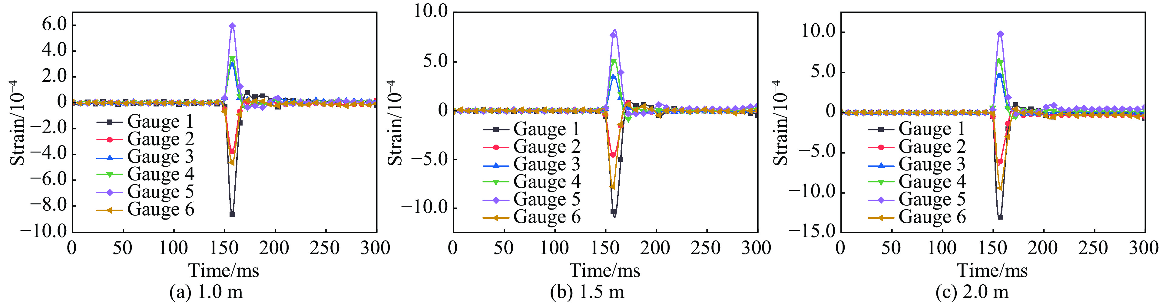
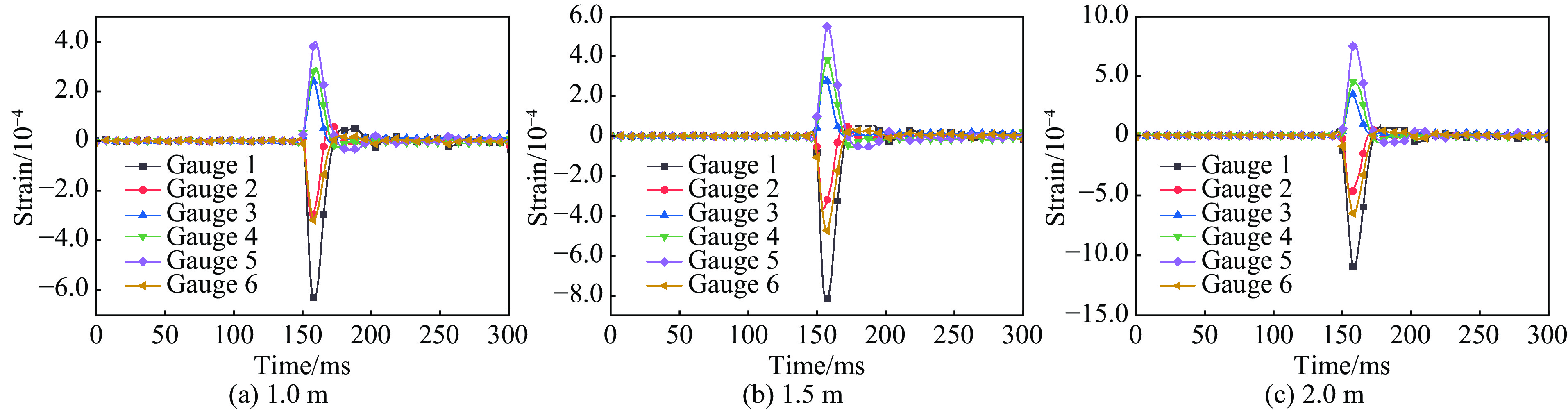
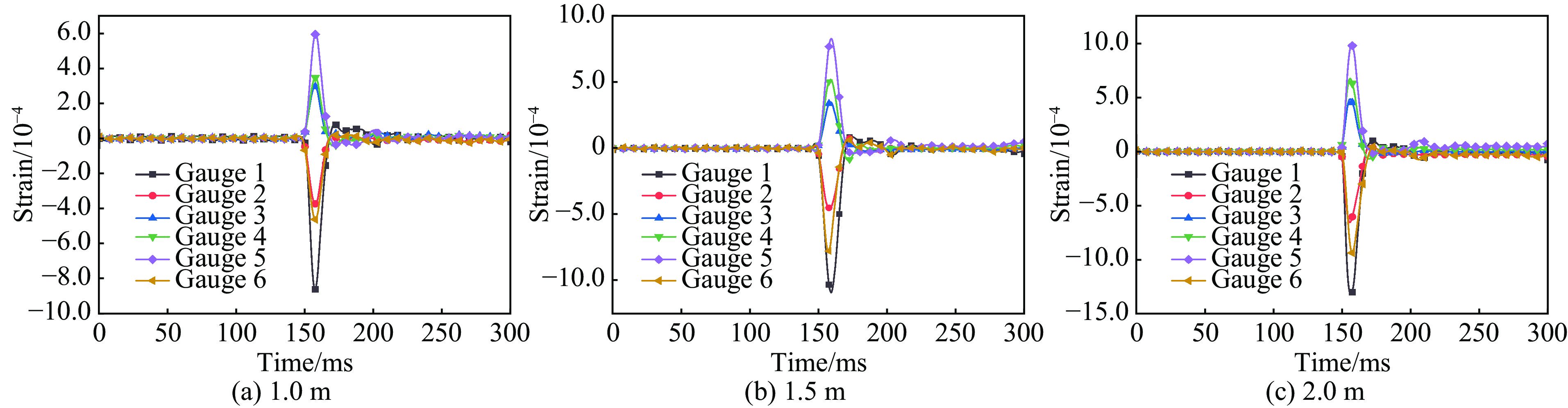
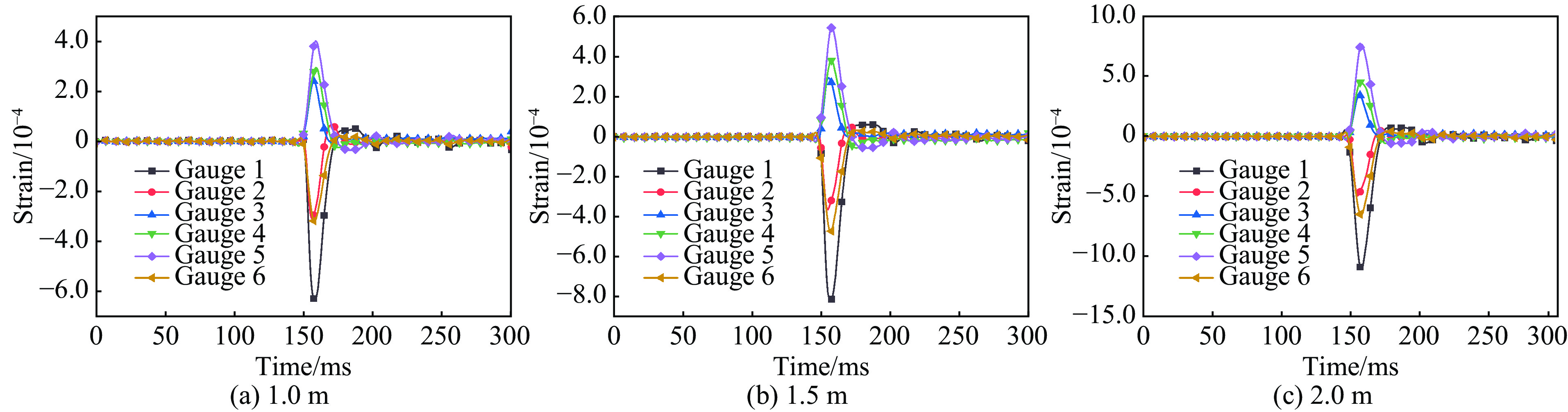
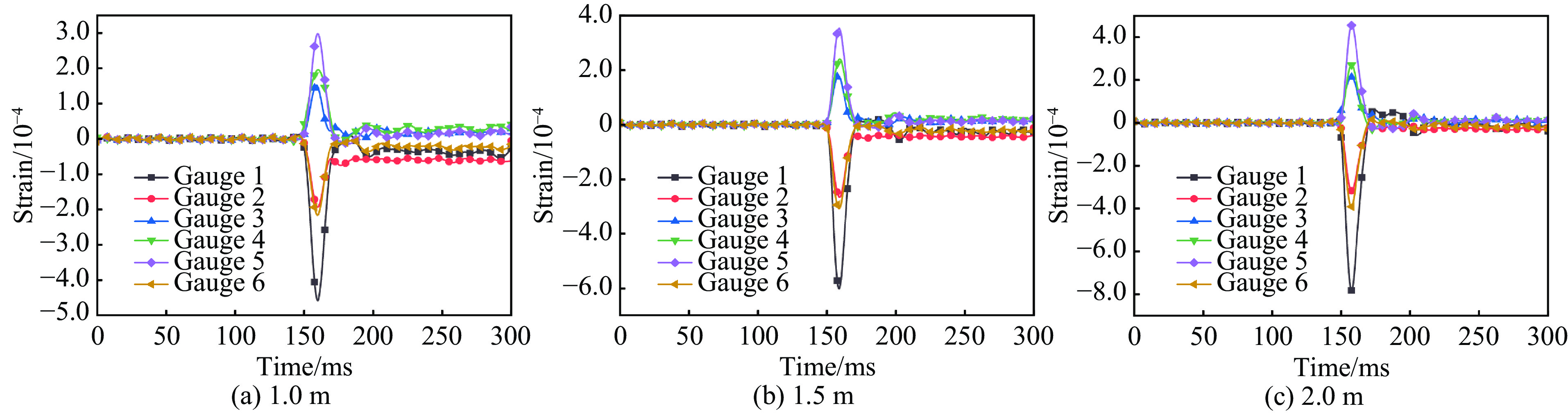
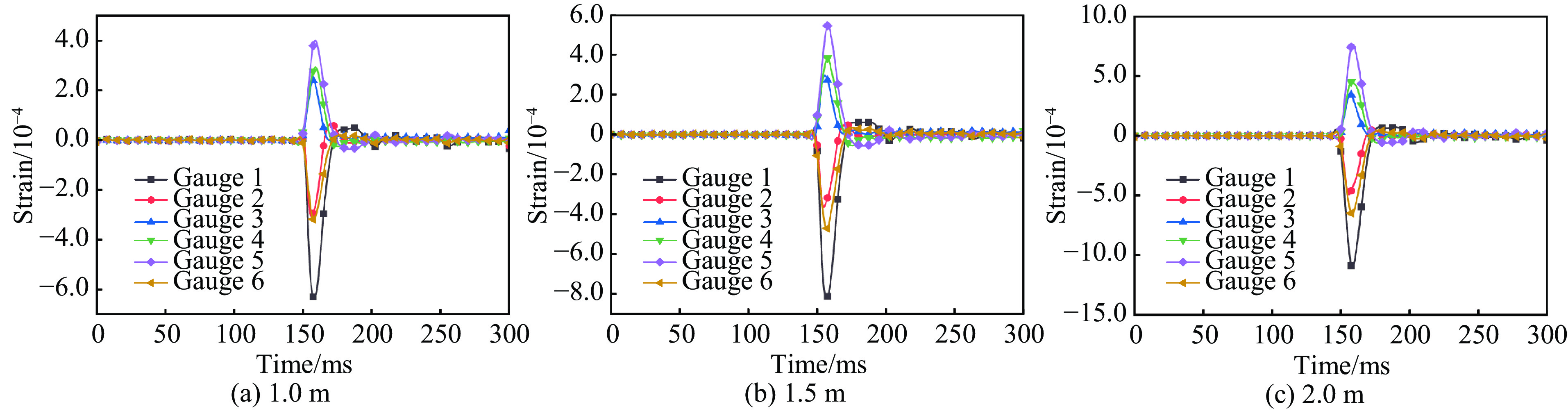
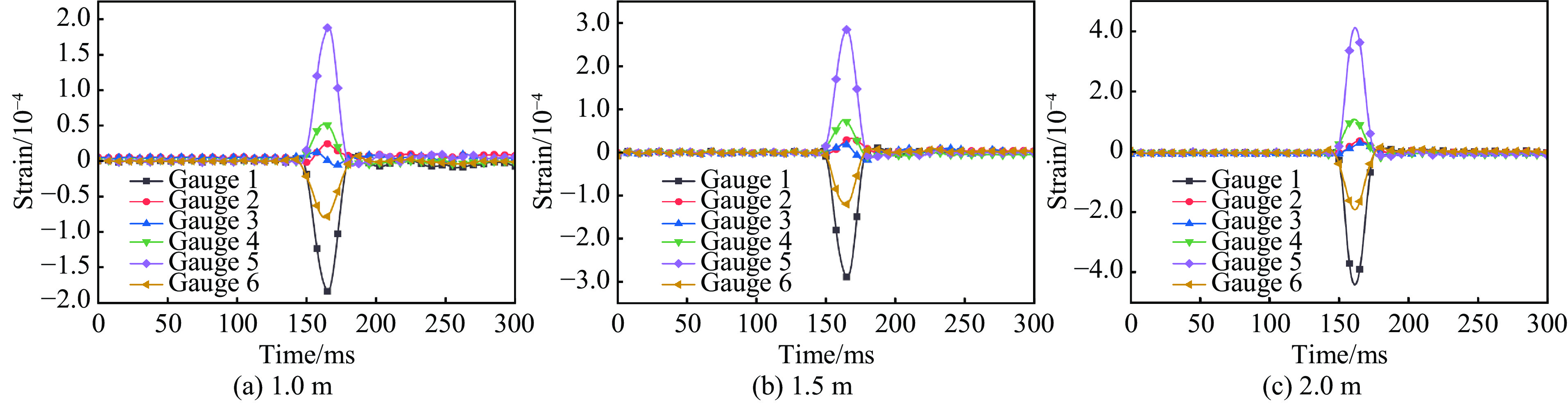
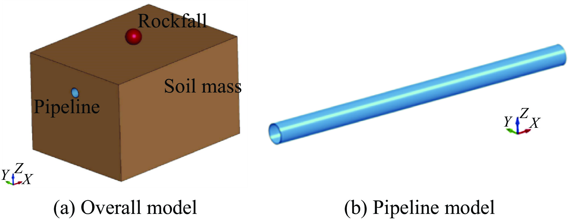
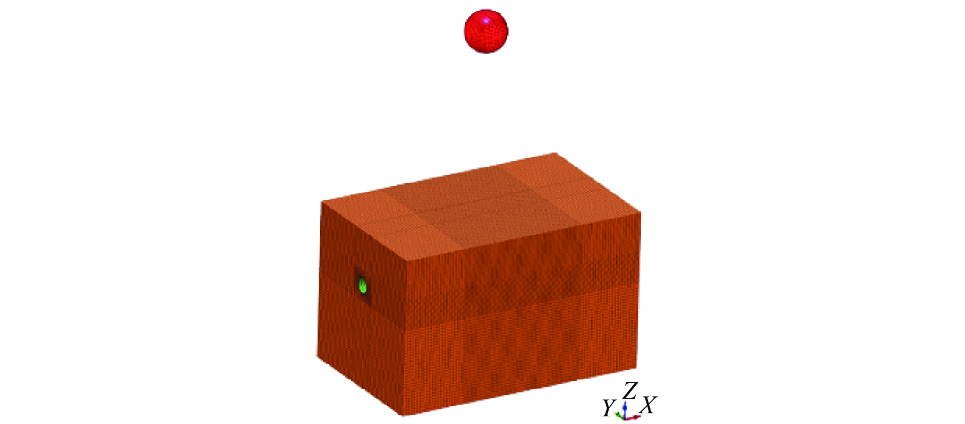
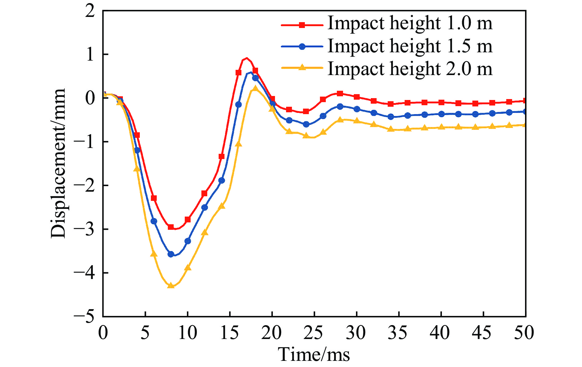
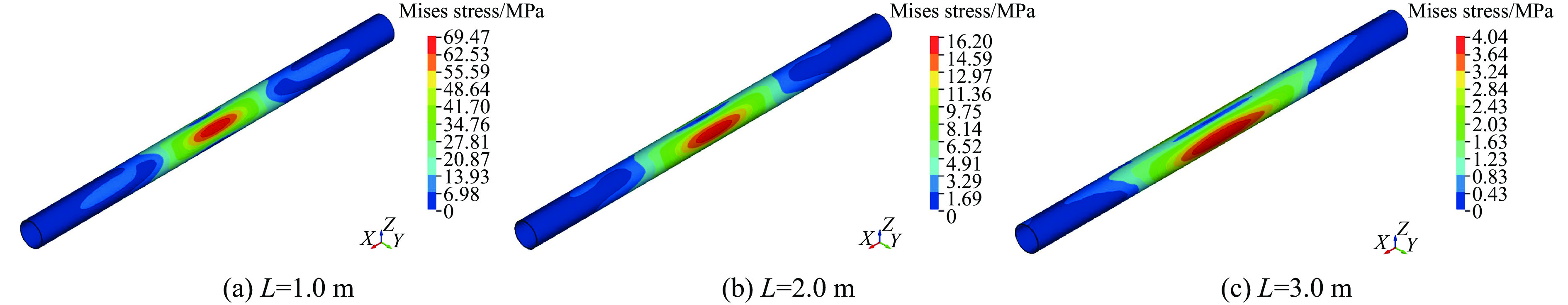
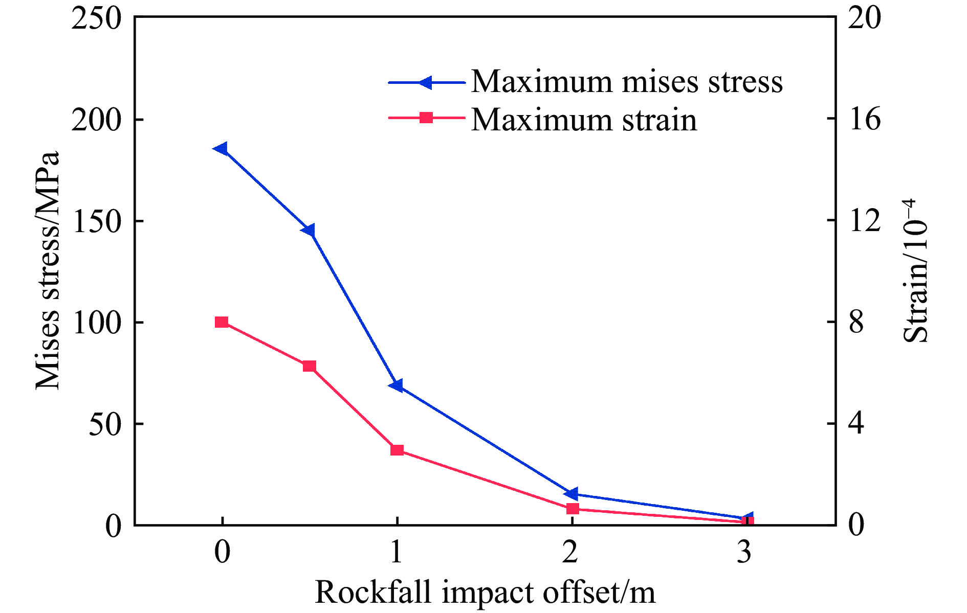
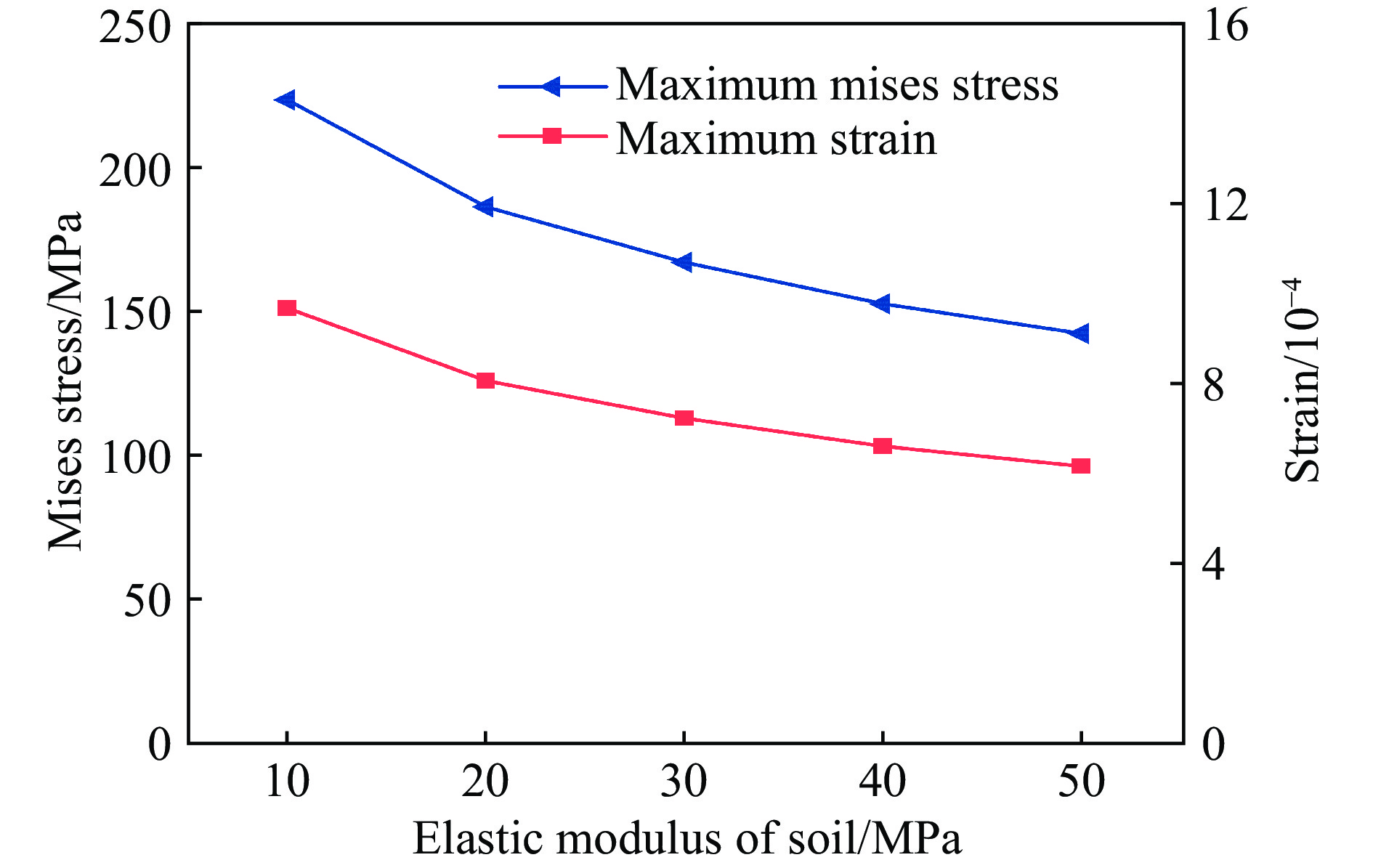
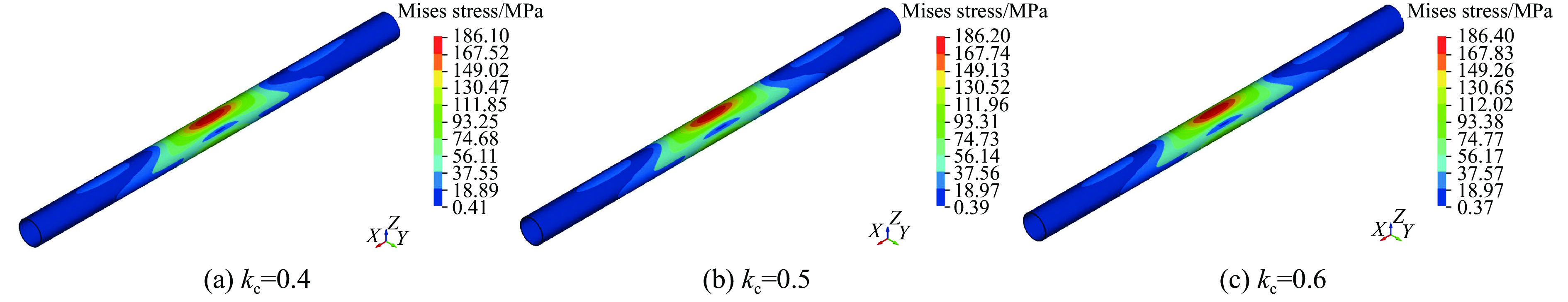
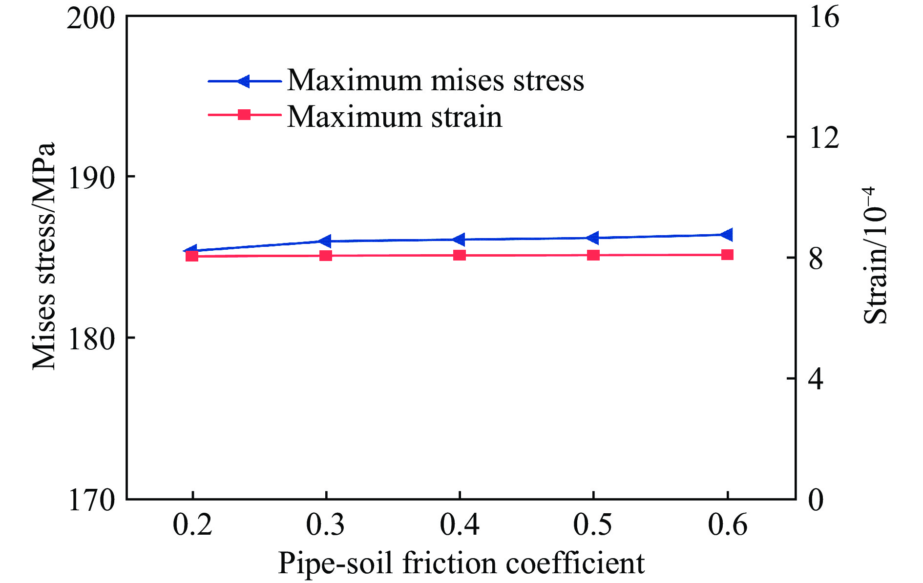
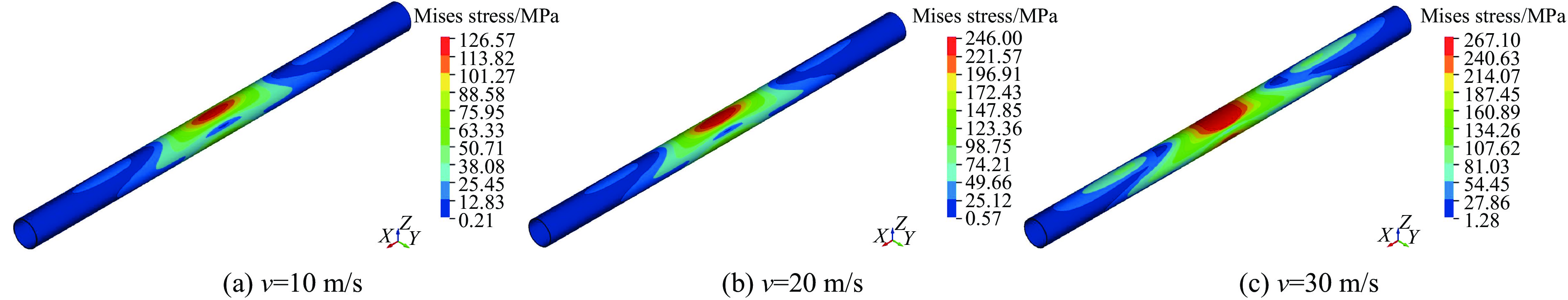
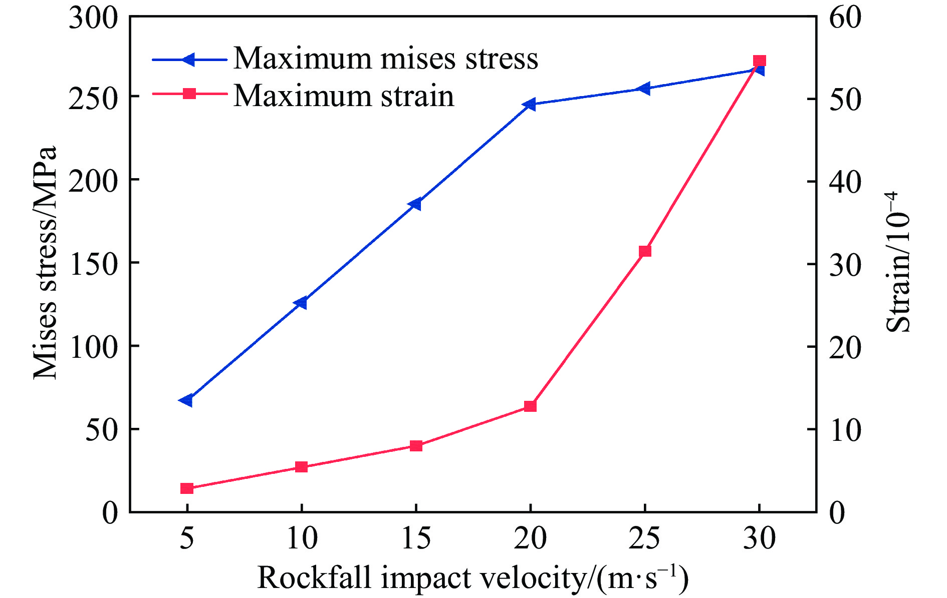
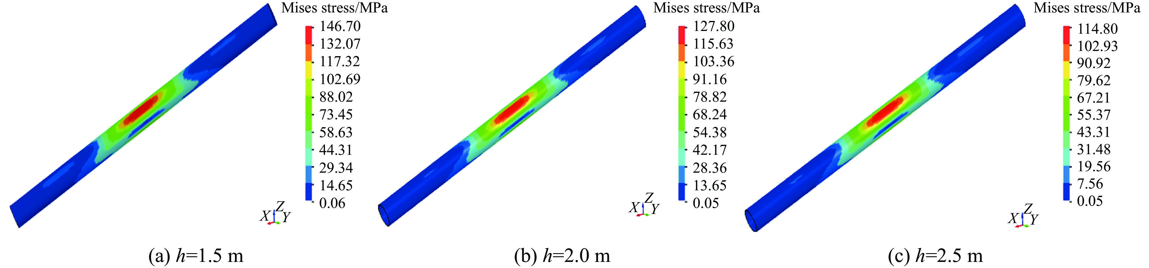
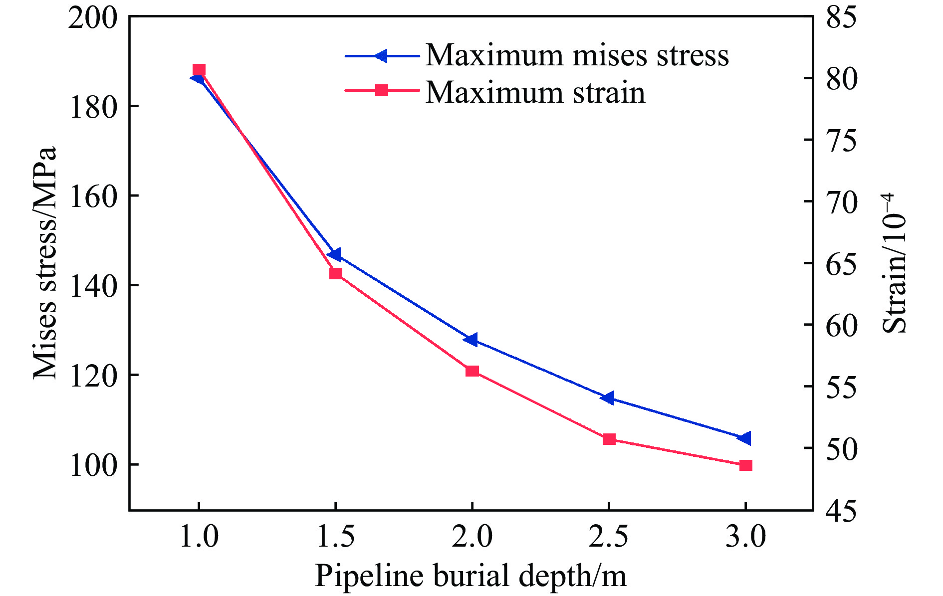
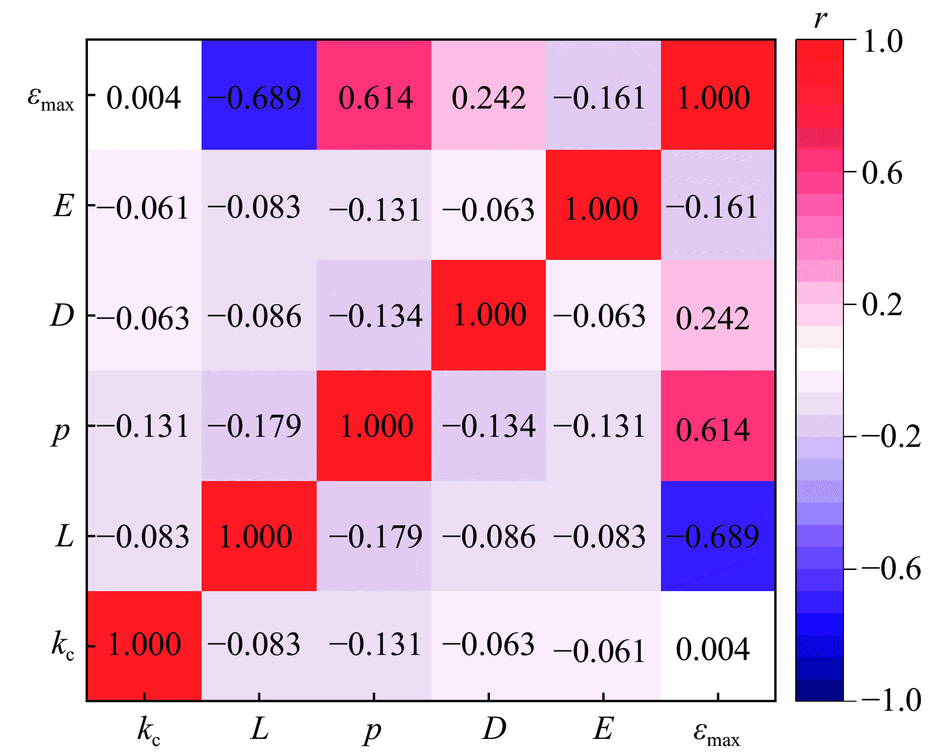
In view of the rockfall impact threat faced by buried pipelines in high-risk areas of geological disasters, this study systematically investigated the dynamic response characteristics of buried pipelines through a combination of scale model test and numerical simulation to further explore its dynamic response characteristics and dig deep into their intrinsic mechanisms. A test model with a geometric scale ratio of 1:10 was constructed. Meanwhile, a drop hammer impact test device combined with LS-DYNA finite element analysis was used. Based on these above, the influence laws of pipeline burial depth, wall thickness, impact parameters, pipeline parameters, and soil properties (including soil elastic modulus and pipe-soil friction coefficient) on buried pipelines were explored. The test results show that at the same impact height, the peak strain decreases as the pipeline’s burial depth and wall thickness increase. Under eccentric drop hammer impacts, the influence on the upper and lower cross-sections of the pipeline diminishes as the impact point deviates from the pipeline center. Additionally, a higher impact height corresponds to a greater peak strain in the middle section of the pipeline.The numerical simulation results indicate that the maximum stress and strain of the pipeline are positively correlated with pipeline diameter, internal pressure, and impact velocity, while negatively correlated with impact eccentricity, soil elastic modulus, and pipeline burial depth. Moreover, the increase in the pipe-soil friction coefficient has a limited impact on pipeline stress and strain, and this effect becomes negligible when it exceeds 0.3.Based on Pearson correlation analysis, the order of influence degree of each parameter is impact eccentricity, pipeline internal pressure, pipeline diameter, ,soil elastic modulus,, and pipe-soil friction coefficient,. Among them, pipeline internal pressure, pipeline diameter, and pipe-soil friction coefficient are positively correlated with strain, while soil elastic modulus and impact eccentricity are negatively correlated with strain. The rockfall impact eccentricity and pipeline internal pressure have a moderate to strong correlation with the impact response of buried pipelines.The research results can provide a basis for the safety design of buried pipelines in high-risk areas.
In view of the rockfall impact threat faced by buried pipelines in high-risk areas of geological disasters, this study systematically investigated the dynamic response characteristics of buried pipelines through a combination of scale model test and numerical simulation to further explore its dynamic response characteristics and dig deep into their intrinsic mechanisms. A test model with a geometric scale ratio of 1:10 was constructed. Meanwhile, a drop hammer impact test device combined with LS-DYNA finite element analysis was used. Based on these above, the influence laws of pipeline burial depth, wall thickness, impact parameters, pipeline parameters, and soil properties (including soil elastic modulus and pipe-soil friction coefficient) on buried pipelines were explored. The test results show that at the same impact height, the peak strain decreases as the pipeline’s burial depth and wall thickness increase. Under eccentric drop hammer impacts, the influence on the upper and lower cross-sections of the pipeline diminishes as the impact point deviates from the pipeline center. Additionally, a higher impact height corresponds to a greater peak strain in the middle section of the pipeline.The numerical simulation results indicate that the maximum stress and strain of the pipeline are positively correlated with pipeline diameter, internal pressure, and impact velocity, while negatively correlated with impact eccentricity, soil elastic modulus, and pipeline burial depth. Moreover, the increase in the pipe-soil friction coefficient has a limited impact on pipeline stress and strain, and this effect becomes negligible when it exceeds 0.3.Based on Pearson correlation analysis, the order of influence degree of each parameter is impact eccentricity, pipeline internal pressure, pipeline diameter, ,soil elastic modulus,, and pipe-soil friction coefficient,. Among them, pipeline internal pressure, pipeline diameter, and pipe-soil friction coefficient are positively correlated with strain, while soil elastic modulus and impact eccentricity are negatively correlated with strain. The rockfall impact eccentricity and pipeline internal pressure have a moderate to strong correlation with the impact response of buried pipelines.The research results can provide a basis for the safety design of buried pipelines in high-risk areas.


Dynamic response and failure mechanism for urban continuous beam bridges under far-field blast loads
, Available online , doi: 10.11883/bzycj-2025-0170
Abstract:
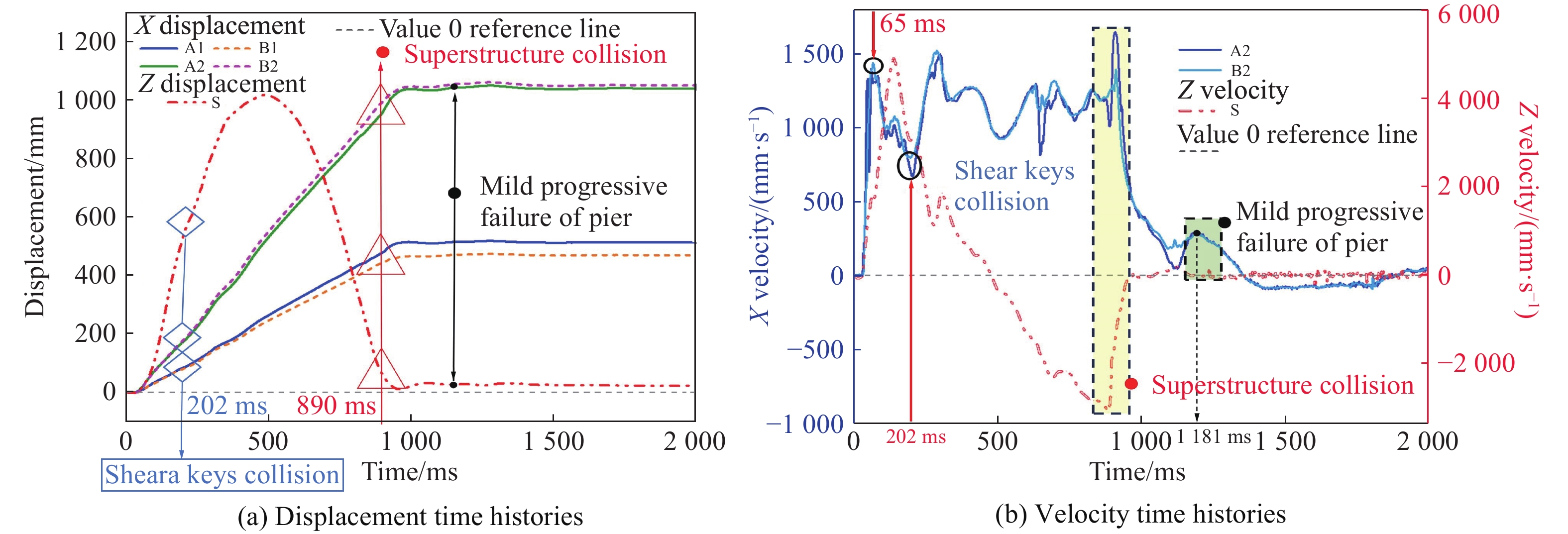
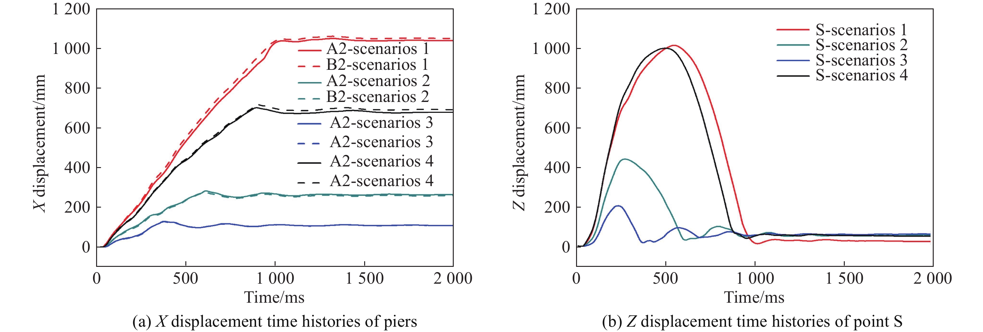
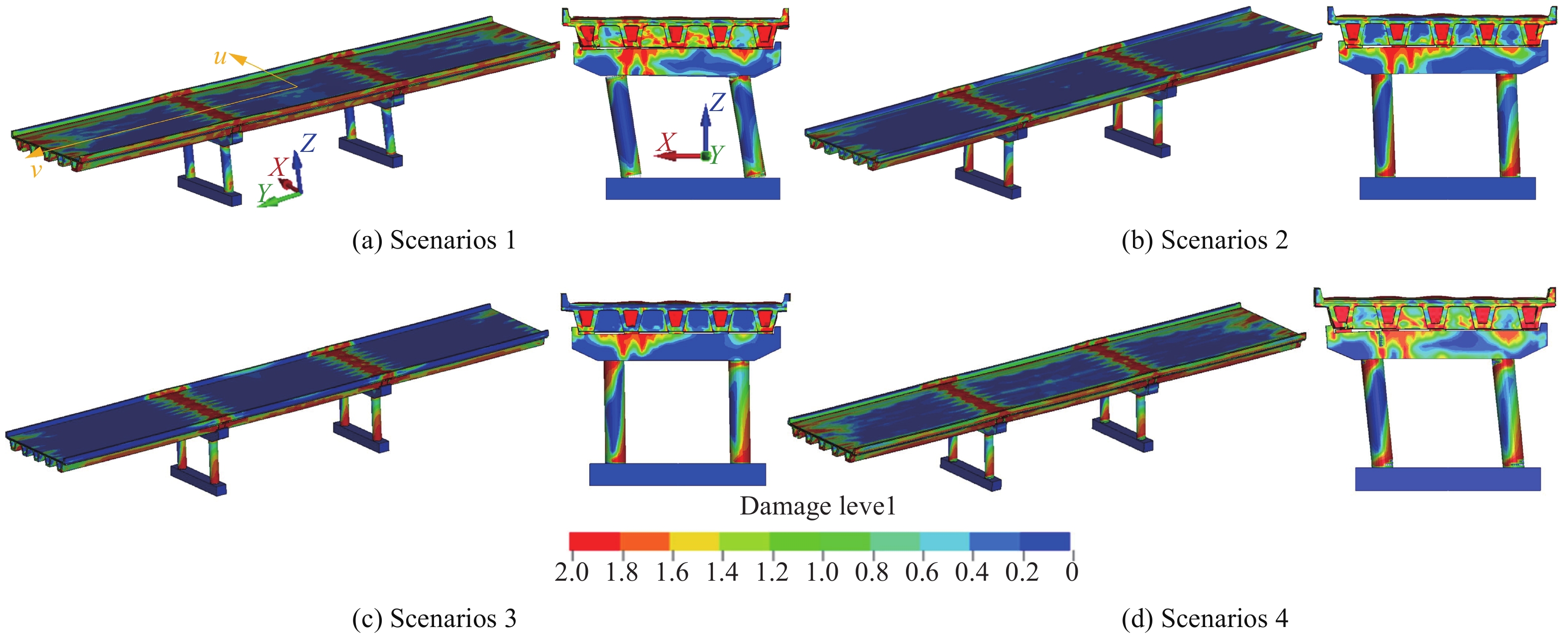
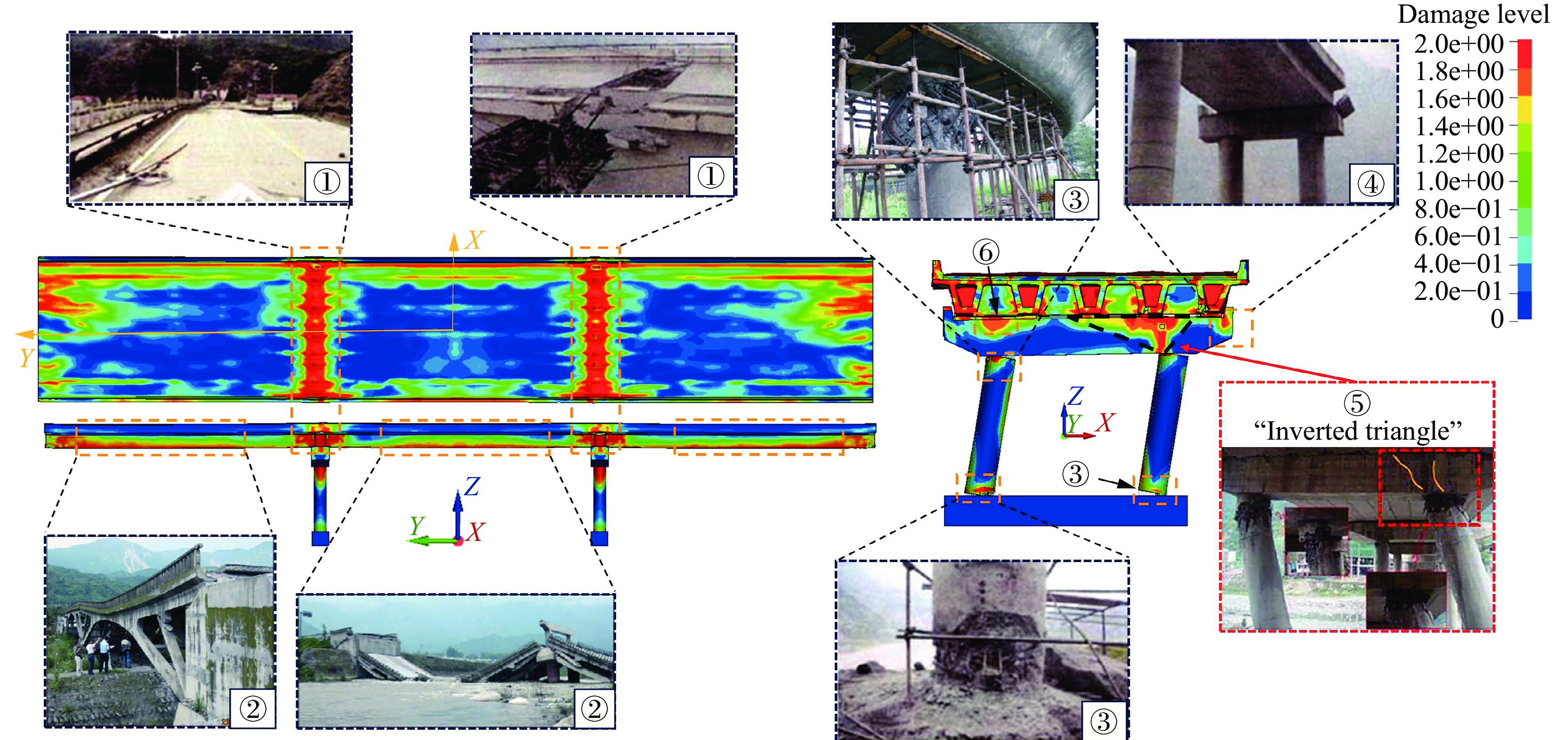
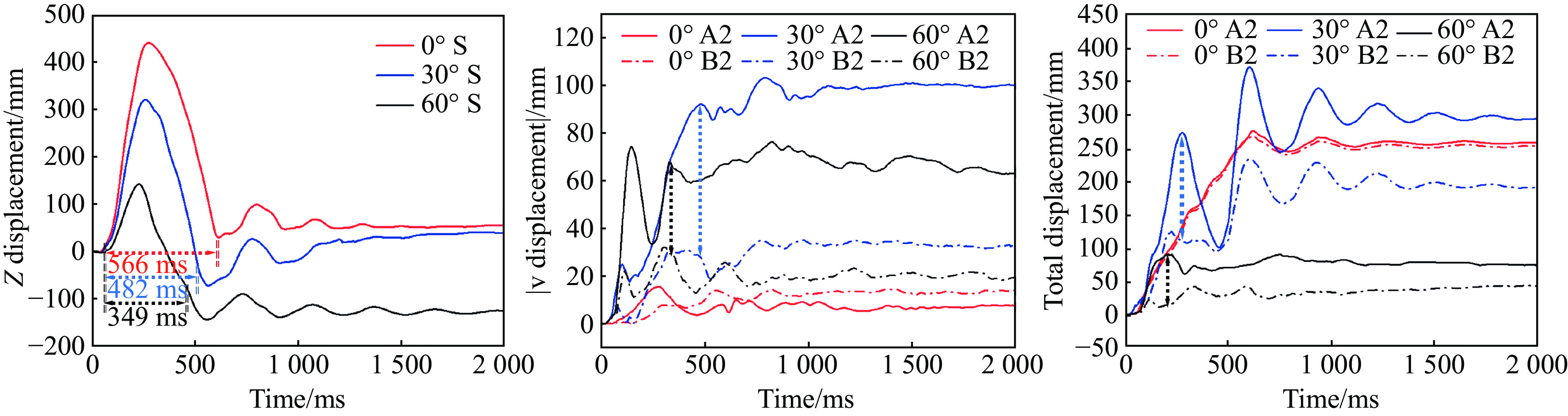
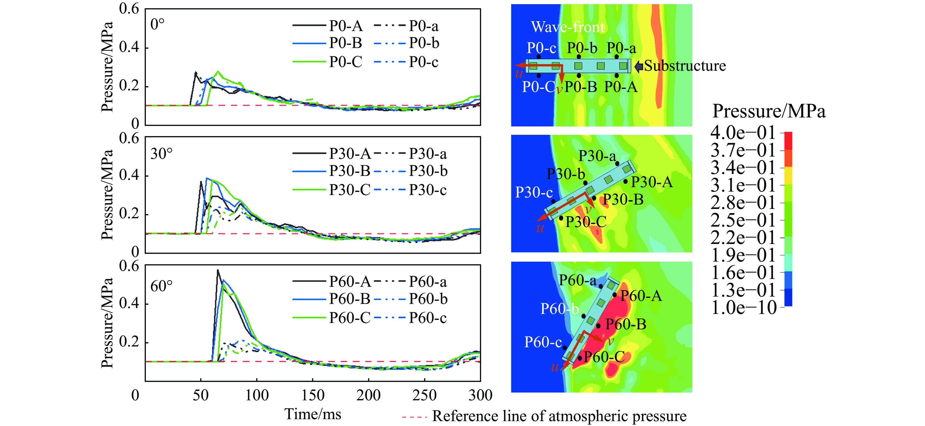
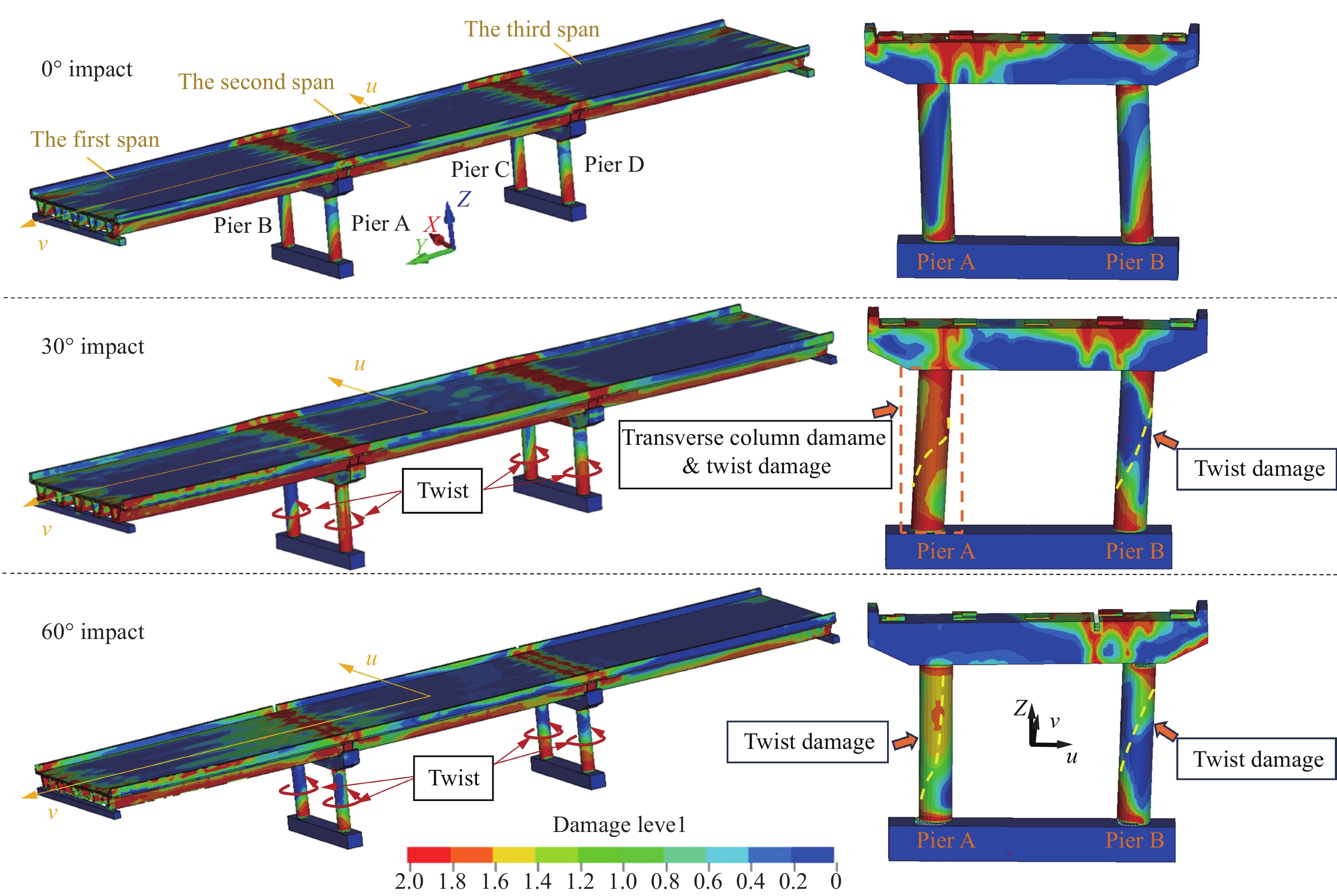
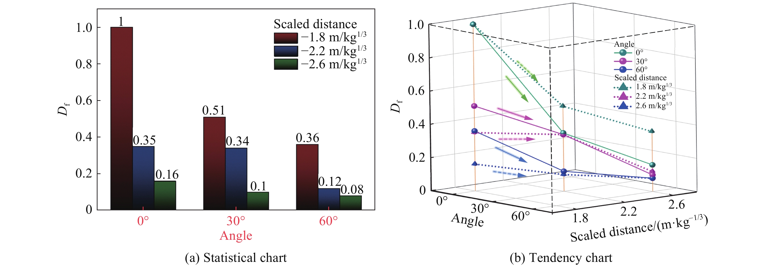
Urban bridges are frequently exposed to blast threats arising from accidental explosions and terrorist attacks. However, existing studies on bridge responses under blast loading remain limited, particularly for far-field blast conditions. To investigate the dynamic response and damage mechanisms of urban continuous beam bridges subjected to far-field blast loading, LS-DYNA was employed to efficiently apply blast loads and perform numerical simulations accounting for blast-induced fluid–structure interaction. Based on a typical continuous beam bridge, a refined numerical model was developed to analyze the response process and representative damage modes of the bridge under different blast scenarios. Furthermore, the effects of blast distance, explosive charge weight, and impact angle on structural response and damage were systematically examined. The results indicate that, under far-field blast loading, the continuous beam bridge exhibits a global structural response, with uplift of the superstructure and tilting of the bridge piers being the dominant characteristics. The uplift of the superstructure is primarily influenced by the blast load and the spatial geometric characteristics of the bridge, whereas the tilting of the piers is associated with the direct action of the blast wave and the displacement of the superstructure. Under perpendicular impact, typical damage modes include wet joint failure, flexural deformation of box girders, crushing damage at the tops and bases of piers, and bending cracks in bent caps. Under oblique blast loading, torsional deformation of pier columns is additionally observed in the substructure. A decrease in the impact angle or the scaled distance results in an increase in the overall damage of the bridge structure. Evaluation based on the proposed weighted damage factor indicates that, compared with the impact angle, the overall damage of the continuous beam bridge is more sensitive to variations in the scaled distance. The findings of this study provide useful analytical approaches and mechanistic insights for understanding blast responses and guiding the blast-resistant design of bridge structures.
Urban bridges are frequently exposed to blast threats arising from accidental explosions and terrorist attacks. However, existing studies on bridge responses under blast loading remain limited, particularly for far-field blast conditions. To investigate the dynamic response and damage mechanisms of urban continuous beam bridges subjected to far-field blast loading, LS-DYNA was employed to efficiently apply blast loads and perform numerical simulations accounting for blast-induced fluid–structure interaction. Based on a typical continuous beam bridge, a refined numerical model was developed to analyze the response process and representative damage modes of the bridge under different blast scenarios. Furthermore, the effects of blast distance, explosive charge weight, and impact angle on structural response and damage were systematically examined. The results indicate that, under far-field blast loading, the continuous beam bridge exhibits a global structural response, with uplift of the superstructure and tilting of the bridge piers being the dominant characteristics. The uplift of the superstructure is primarily influenced by the blast load and the spatial geometric characteristics of the bridge, whereas the tilting of the piers is associated with the direct action of the blast wave and the displacement of the superstructure. Under perpendicular impact, typical damage modes include wet joint failure, flexural deformation of box girders, crushing damage at the tops and bases of piers, and bending cracks in bent caps. Under oblique blast loading, torsional deformation of pier columns is additionally observed in the substructure. A decrease in the impact angle or the scaled distance results in an increase in the overall damage of the bridge structure. Evaluation based on the proposed weighted damage factor indicates that, compared with the impact angle, the overall damage of the continuous beam bridge is more sensitive to variations in the scaled distance. The findings of this study provide useful analytical approaches and mechanistic insights for understanding blast responses and guiding the blast-resistant design of bridge structures.
, Available online , doi: 10.11883/bzycj-2025-0023
Abstract:
The study aims to solve the problem of calculating the thickness limit of high-strength steel-concrete composite structures under the impact of slender thin-walled projectiles, a key consideration for protective engineering design. A series of impact tests on composite targets were carried out. These targets were composed of different high-strength steel plates and concrete backplates. Slender thin-walled projectiles were launched with a gas gun at controlled velocities, and the impact process were captured by high-speed cameras. The resulting damage to the structures and the failure modes of the projectiles were analyzed using both non-destructive and destructive testing methods. Based on test results, the protective mechanism of the composite structures and the failure modes of projectiles were analyzed. An improved thickness limit calculation model was then developed. Unlike the original model, this new model incorporated the structural strength of slender thin-walled projectiles, considering their wall thickness, material yield strength, and geometric dimensions, and was established based on force equilibrium and energy conservation principles. The results show that the high-strength steel in the composite structures provides material strength to resist penetration, while the concrete backplate offers support stiffness. As slender thin-walled projectiles are prone to compression and expansion cracking during impact, their structural strength must be factored into the calculation model. Moreover, the design of composite structures should consider both the mechanical properties of high-strength steel and the thickness limit. In conclusion, though the proposed model offers a new theoretical approach, it has limitations such as empirical parameters and conservative results. Further research is necessary to refine and enhance the model. The study's findings provide a theoretical basis for the design and application of high-strength steel-concrete composite structures in protective engineering.
The study aims to solve the problem of calculating the thickness limit of high-strength steel-concrete composite structures under the impact of slender thin-walled projectiles, a key consideration for protective engineering design. A series of impact tests on composite targets were carried out. These targets were composed of different high-strength steel plates and concrete backplates. Slender thin-walled projectiles were launched with a gas gun at controlled velocities, and the impact process were captured by high-speed cameras. The resulting damage to the structures and the failure modes of the projectiles were analyzed using both non-destructive and destructive testing methods. Based on test results, the protective mechanism of the composite structures and the failure modes of projectiles were analyzed. An improved thickness limit calculation model was then developed. Unlike the original model, this new model incorporated the structural strength of slender thin-walled projectiles, considering their wall thickness, material yield strength, and geometric dimensions, and was established based on force equilibrium and energy conservation principles. The results show that the high-strength steel in the composite structures provides material strength to resist penetration, while the concrete backplate offers support stiffness. As slender thin-walled projectiles are prone to compression and expansion cracking during impact, their structural strength must be factored into the calculation model. Moreover, the design of composite structures should consider both the mechanical properties of high-strength steel and the thickness limit. In conclusion, though the proposed model offers a new theoretical approach, it has limitations such as empirical parameters and conservative results. Further research is necessary to refine and enhance the model. The study's findings provide a theoretical basis for the design and application of high-strength steel-concrete composite structures in protective engineering.

, Available online , doi: 10.11883/bzycj-2026-0017
Abstract:
Ceramic/metal composite armor has attracted extensive attention in lightweight protective structures because of its high hardness, excellent energy dissipation capability, and strong resistance to repeated impacts. However, most existing studies focus on uniformly distributed ceramic balls and single-impact scenarios, leaving the damage evolution and protective mechanisms of gradient ceramic-ball composites under multiple impacts insufficiently understood. To address these limitations, a gradient ceramic-ball metal composite structure was proposed to improve the multi-hit resistance of composite armor. Penetration experiments using 12.7 mm armor-piercing incendiary projectiles were conducted to investigate the ballistic response of the composite target. Based on the experimental conditions, numerical simulations were carried out using the LS-DYNA software to analyze the penetration behavior of successive projectiles impacting the composite target plate. A three-dimensional finite element model was established to reproduce the penetration process, in which the Johnson–Cook constitutive model was employed to describe the mechanical behavior of metallic components and the Johnson–Holmquist ceramic constitutive model was adopted to characterize the dynamic response and failure behavior of ceramic materials. Appropriate contact algorithms and erosion criteria were implemented to simulate the interaction, damage, and fragmentation processes between the projectile and the target materials. Parametric numerical simulations were further performed to analyze the penetration characteristics of successive projectiles during the multi-impact process. The effects of ceramic ball diameter, impact spacing between successive projectiles, and gradient arrangement direction of ceramic balls on the ballistic performance of the composite structure were systematically investigated. In addition, the penetration depth, energy absorption characteristics, damage morphology of the target, and projectile deflection behavior were analyzed to reveal the influence of structural heterogeneity and pre-existing damage on the penetration response. The results show that increasing the diameter of ceramic balls significantly enlarges the damage region and enhances the structural non-uniformity, thereby increasing the sensitivity of the structure to impact location. Under multiple projectile impact conditions, the pre-existing damage caused by the first projectile significantly reduces the energy absorption capacity of the target plate and alters the penetration behavior of the subsequent projectile, especially when the impact point of the latter is located within the damaged region. Within a certain range of impact spacing, projectile deflection induced by damage heterogeneity effectively reduces the penetration depth of the backing plate even when the absorbed kinetic energy remains nearly unchanged. Compared with the negative-gradient configuration, the positive-gradient ceramic-ball composite armor reduces the damage area of the first ceramic layer by 14.8%–57.8% under the same areal density and effectively restricts the expansion of the initial damage region, thereby maintaining higher structural integrity under repeated impacts. These results indicate that a properly designed gradient distribution of ceramic balls can significantly improve the multi-hit resistance of ceramic/metal composite armor and provide useful guidance for the lightweight design and structural optimization of gradient ceramic-ball composite armor.
Ceramic/metal composite armor has attracted extensive attention in lightweight protective structures because of its high hardness, excellent energy dissipation capability, and strong resistance to repeated impacts. However, most existing studies focus on uniformly distributed ceramic balls and single-impact scenarios, leaving the damage evolution and protective mechanisms of gradient ceramic-ball composites under multiple impacts insufficiently understood. To address these limitations, a gradient ceramic-ball metal composite structure was proposed to improve the multi-hit resistance of composite armor. Penetration experiments using 12.7 mm armor-piercing incendiary projectiles were conducted to investigate the ballistic response of the composite target. Based on the experimental conditions, numerical simulations were carried out using the LS-DYNA software to analyze the penetration behavior of successive projectiles impacting the composite target plate. A three-dimensional finite element model was established to reproduce the penetration process, in which the Johnson–Cook constitutive model was employed to describe the mechanical behavior of metallic components and the Johnson–Holmquist ceramic constitutive model was adopted to characterize the dynamic response and failure behavior of ceramic materials. Appropriate contact algorithms and erosion criteria were implemented to simulate the interaction, damage, and fragmentation processes between the projectile and the target materials. Parametric numerical simulations were further performed to analyze the penetration characteristics of successive projectiles during the multi-impact process. The effects of ceramic ball diameter, impact spacing between successive projectiles, and gradient arrangement direction of ceramic balls on the ballistic performance of the composite structure were systematically investigated. In addition, the penetration depth, energy absorption characteristics, damage morphology of the target, and projectile deflection behavior were analyzed to reveal the influence of structural heterogeneity and pre-existing damage on the penetration response. The results show that increasing the diameter of ceramic balls significantly enlarges the damage region and enhances the structural non-uniformity, thereby increasing the sensitivity of the structure to impact location. Under multiple projectile impact conditions, the pre-existing damage caused by the first projectile significantly reduces the energy absorption capacity of the target plate and alters the penetration behavior of the subsequent projectile, especially when the impact point of the latter is located within the damaged region. Within a certain range of impact spacing, projectile deflection induced by damage heterogeneity effectively reduces the penetration depth of the backing plate even when the absorbed kinetic energy remains nearly unchanged. Compared with the negative-gradient configuration, the positive-gradient ceramic-ball composite armor reduces the damage area of the first ceramic layer by 14.8%–57.8% under the same areal density and effectively restricts the expansion of the initial damage region, thereby maintaining higher structural integrity under repeated impacts. These results indicate that a properly designed gradient distribution of ceramic balls can significantly improve the multi-hit resistance of ceramic/metal composite armor and provide useful guidance for the lightweight design and structural optimization of gradient ceramic-ball composite armor.


, Available online , doi: 10.11883/bzycj-2025-0222
Abstract:
Although macroscopic finite-element simulations based on classical composite failure criteria such as Hashin’s can account for macroscopic damage mechanisms such as fiber fracture, matrix damage, and delamination, these approaches are unable to represent microscopic damage mechanisms within carbon-fiber-reinforced polymer (CFRP), particularly interfacial debonding between fibers and the matrix. To overcome this limitation, a multiphase micromechanical model was developed that explicitly incorporates distinct constituent phases-fiber, matrix, and interface. This model integrates multiple damage mechanisms such as fiber fracture, matrix failure, and interfacial debonding, enabling a more granular analysis of damage initiation and progression. Periodic boundary conditions were applied to the model to ensure kinematic consistency and mechanical representativeness. A mesh-convergence study was subsequently carried out on the basis of the predicted elastic moduli of CFRP in various material directions, leading to an optimized discretization strategy that balances accuracy and computational cost. Comprehensive validation was performed by comparing the model-predicted stress-strain responses with experimental data obtained from unidirectional CFRP (UD CFRP) under a range of loading conditions, including transverse tension and compression, longitudinal tension and compression, and in-plane and out-of-plane shear. The damage-evolution processes under these representative loading paths were systematically analyzed. The results indicate that the relative errors in peak stress and failure strain between simulations and experiments are less than 5 %. Moreover, the crack-propagation paths predicted by the model show strong agreement with observations from scanning electron microscopy, thereby confirming the accuracy of the proposed microstructure-aware micromechanical modeling framework. Furthermore, the model successfully captures the detailed damage evolution of UD CFRP under various loading scenarios. Under transverse tensile loading, damage is initiated by interfacial debonding, followed by plastic deformation and eventual failure of the matrix near debonded regions. In contrast, under transverse compression, interfacial debonding and matrix plastic deformation are observed to occur simultaneously. Under longitudinal loading, the dominant damage mechanism is identified as fiber fracture, whereas the damage patterns under in-plane and out-of-plane shear are found to be consistent with those under transverse compression and transverse tension, respectively. These insights offer significant engineering value for the development of damage-tolerant design criteria and structural-integrity evaluation frameworks for CFRP components and assemblies.
Although macroscopic finite-element simulations based on classical composite failure criteria such as Hashin’s can account for macroscopic damage mechanisms such as fiber fracture, matrix damage, and delamination, these approaches are unable to represent microscopic damage mechanisms within carbon-fiber-reinforced polymer (CFRP), particularly interfacial debonding between fibers and the matrix. To overcome this limitation, a multiphase micromechanical model was developed that explicitly incorporates distinct constituent phases-fiber, matrix, and interface. This model integrates multiple damage mechanisms such as fiber fracture, matrix failure, and interfacial debonding, enabling a more granular analysis of damage initiation and progression. Periodic boundary conditions were applied to the model to ensure kinematic consistency and mechanical representativeness. A mesh-convergence study was subsequently carried out on the basis of the predicted elastic moduli of CFRP in various material directions, leading to an optimized discretization strategy that balances accuracy and computational cost. Comprehensive validation was performed by comparing the model-predicted stress-strain responses with experimental data obtained from unidirectional CFRP (UD CFRP) under a range of loading conditions, including transverse tension and compression, longitudinal tension and compression, and in-plane and out-of-plane shear. The damage-evolution processes under these representative loading paths were systematically analyzed. The results indicate that the relative errors in peak stress and failure strain between simulations and experiments are less than 5 %. Moreover, the crack-propagation paths predicted by the model show strong agreement with observations from scanning electron microscopy, thereby confirming the accuracy of the proposed microstructure-aware micromechanical modeling framework. Furthermore, the model successfully captures the detailed damage evolution of UD CFRP under various loading scenarios. Under transverse tensile loading, damage is initiated by interfacial debonding, followed by plastic deformation and eventual failure of the matrix near debonded regions. In contrast, under transverse compression, interfacial debonding and matrix plastic deformation are observed to occur simultaneously. Under longitudinal loading, the dominant damage mechanism is identified as fiber fracture, whereas the damage patterns under in-plane and out-of-plane shear are found to be consistent with those under transverse compression and transverse tension, respectively. These insights offer significant engineering value for the development of damage-tolerant design criteria and structural-integrity evaluation frameworks for CFRP components and assemblies.
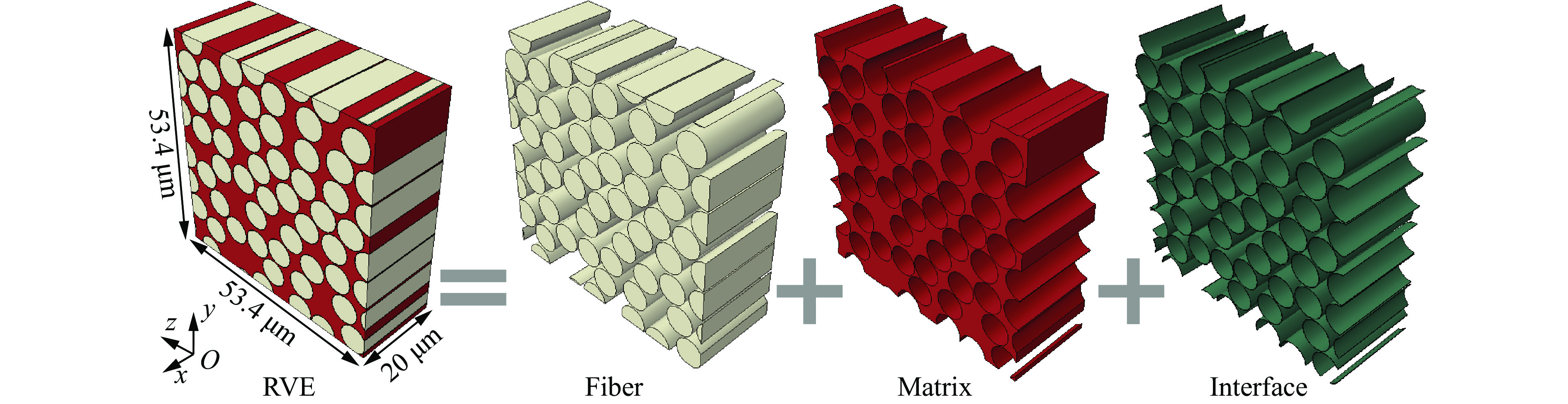
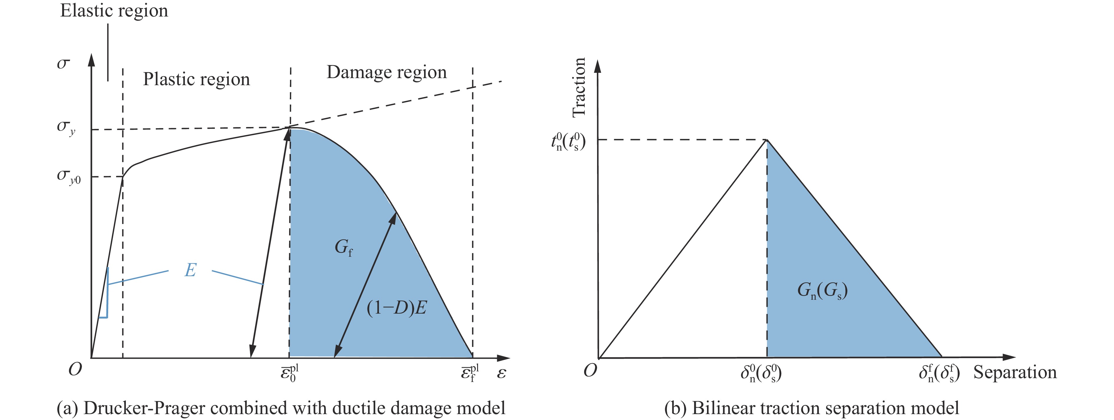
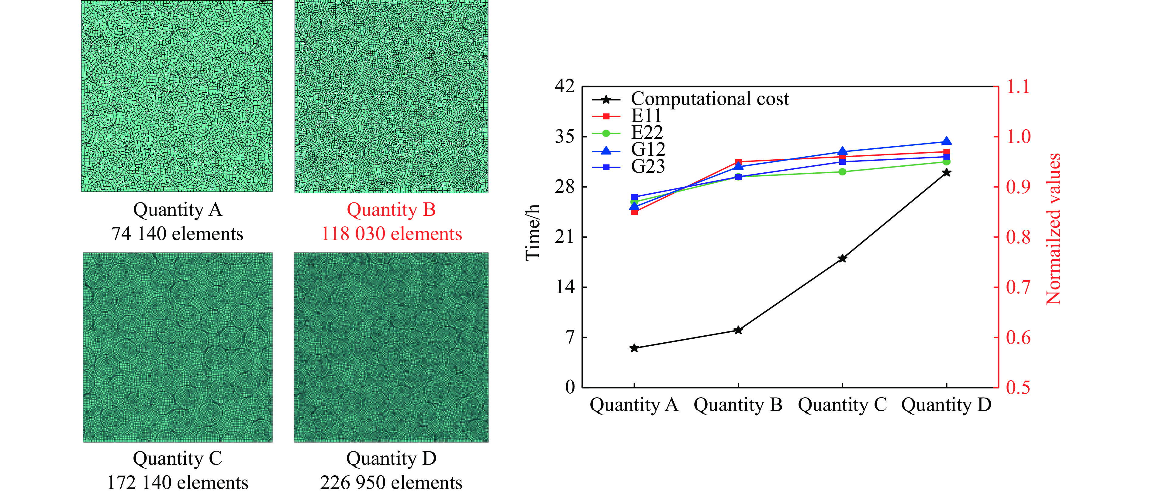
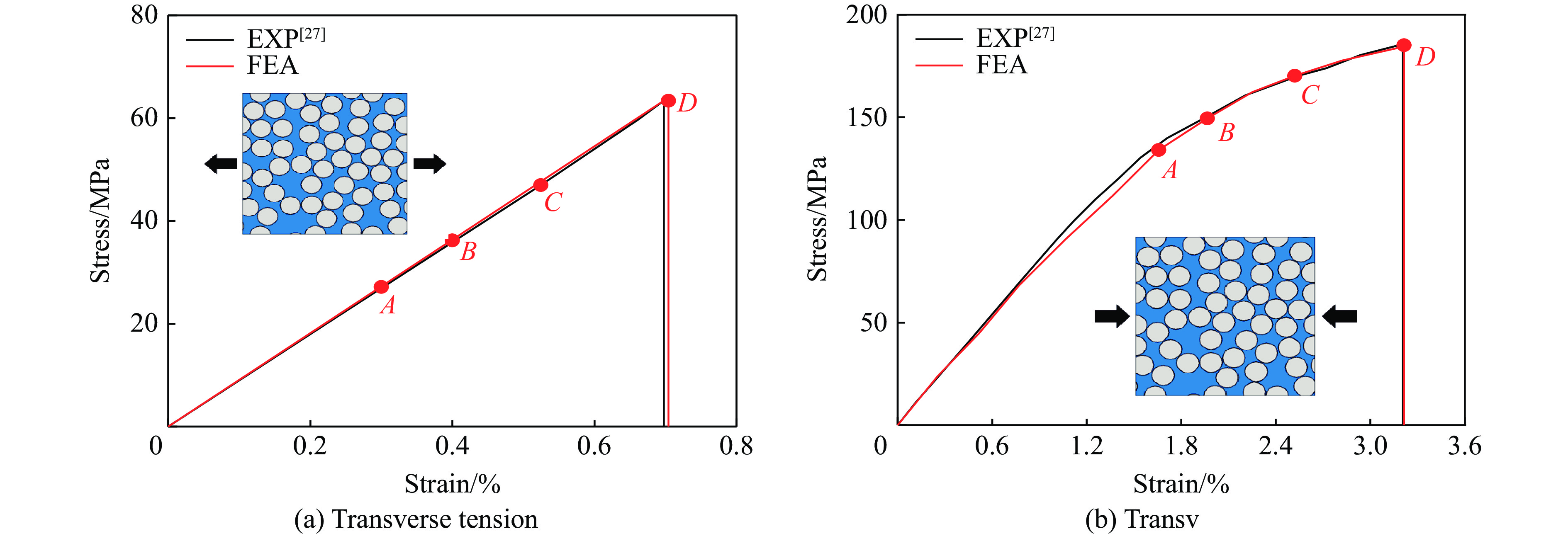
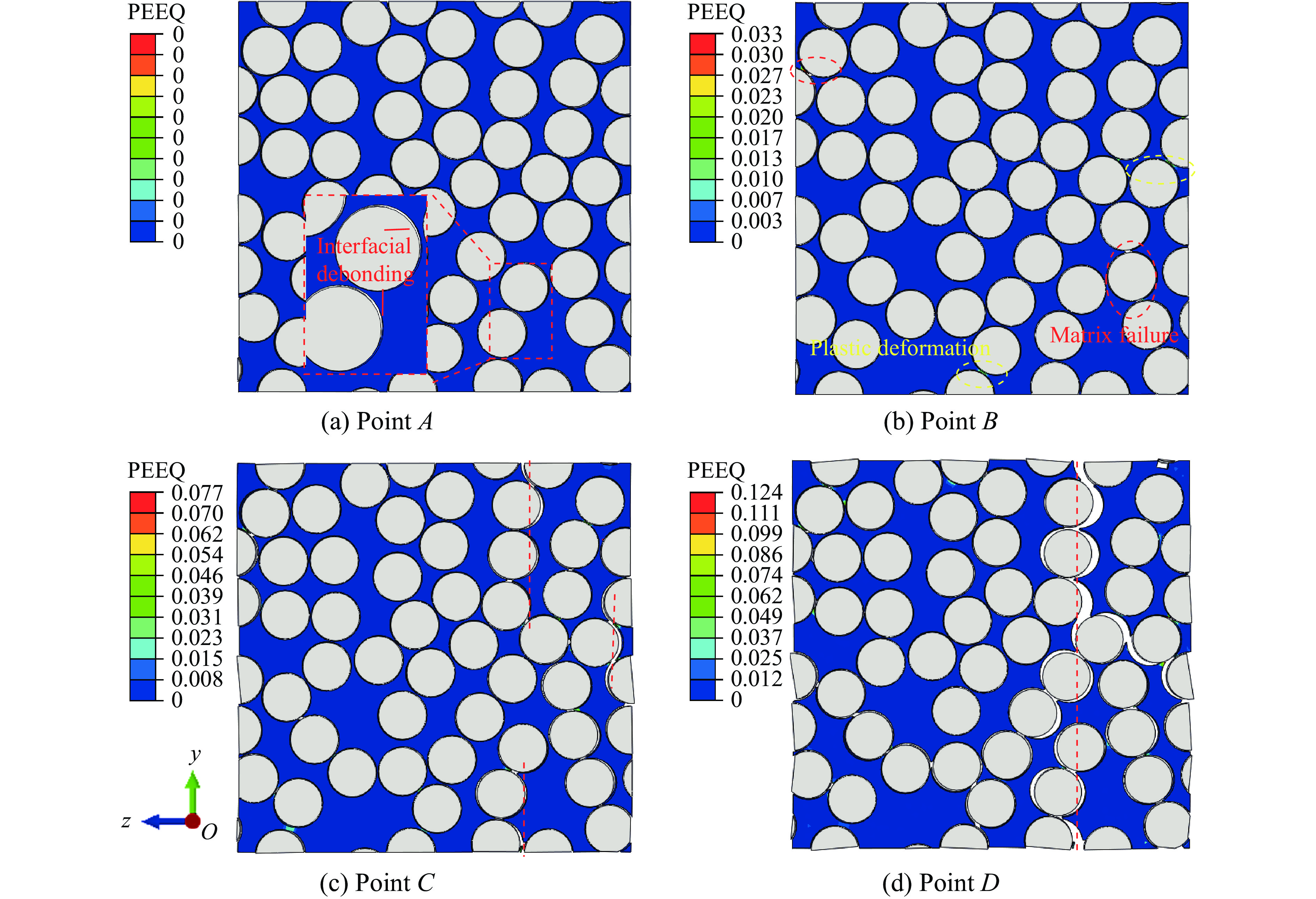
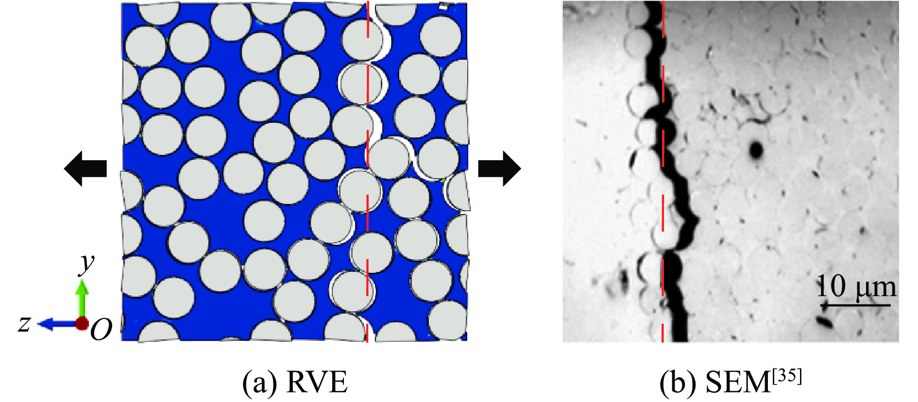
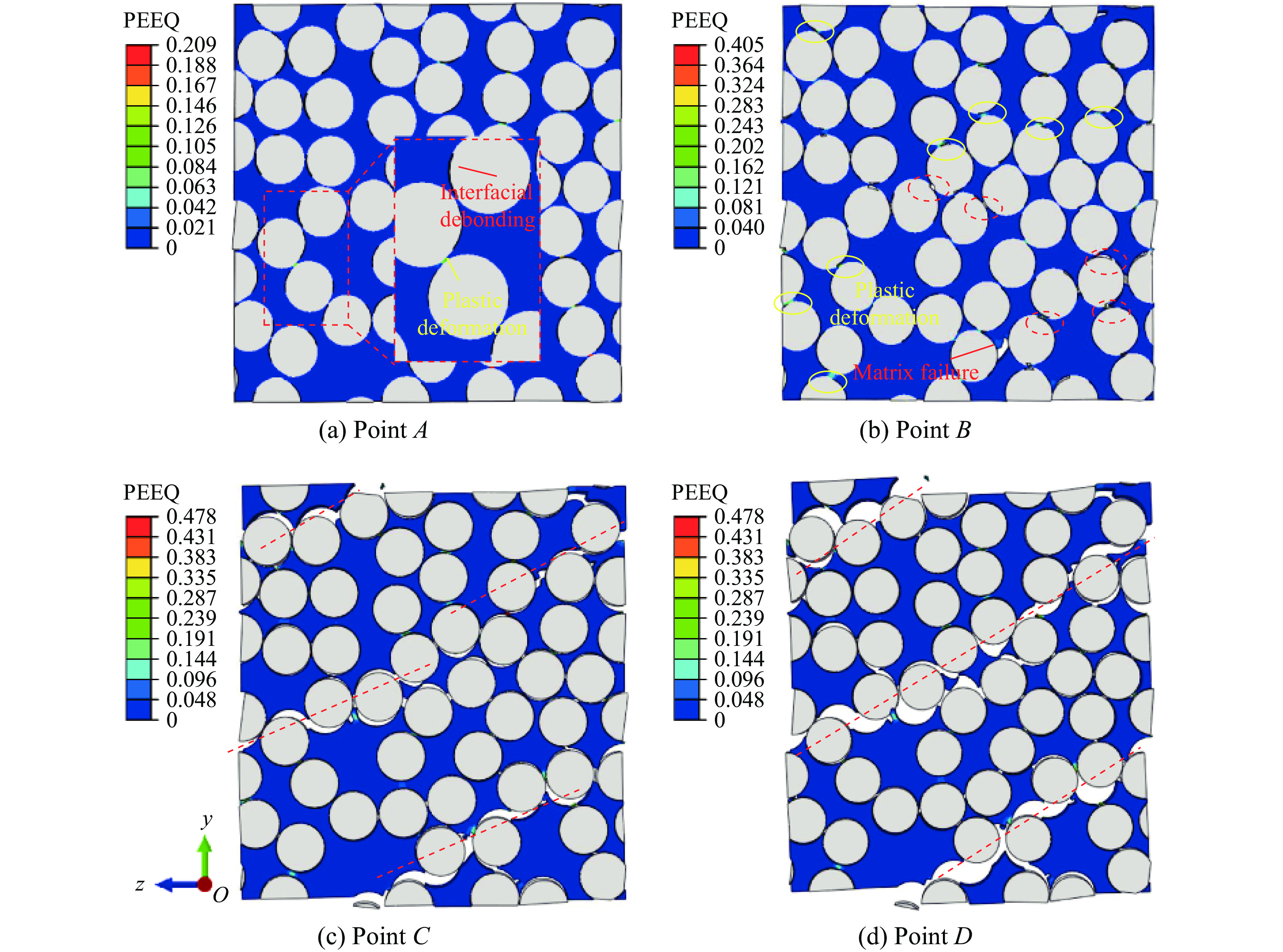
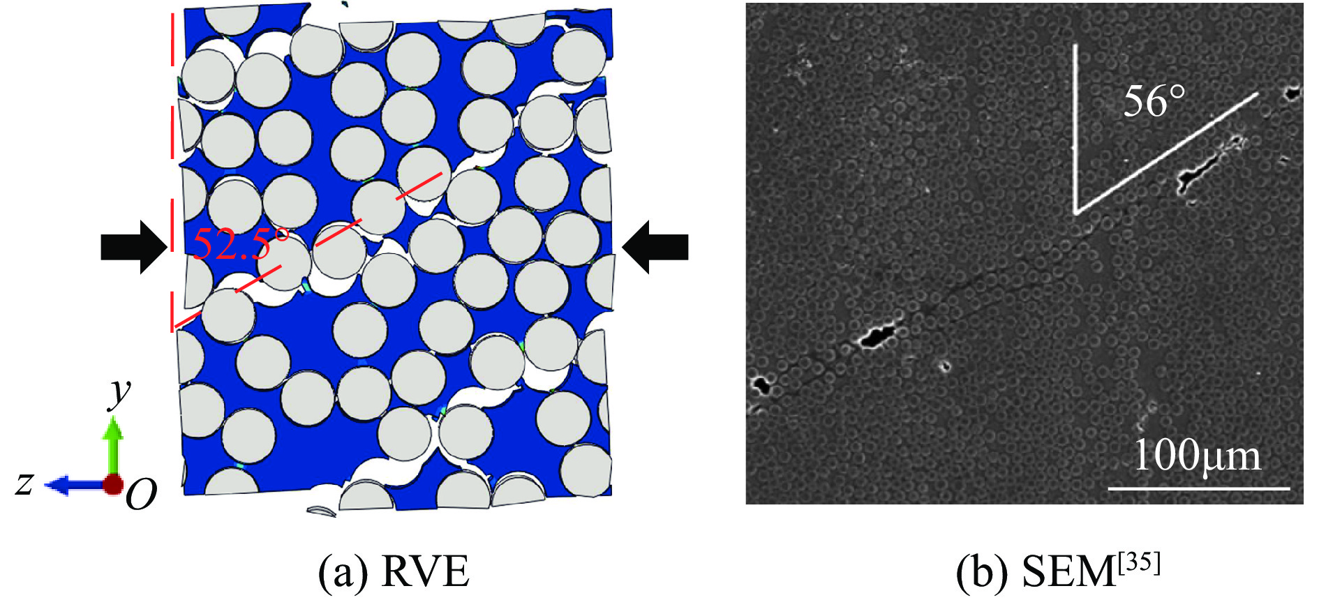
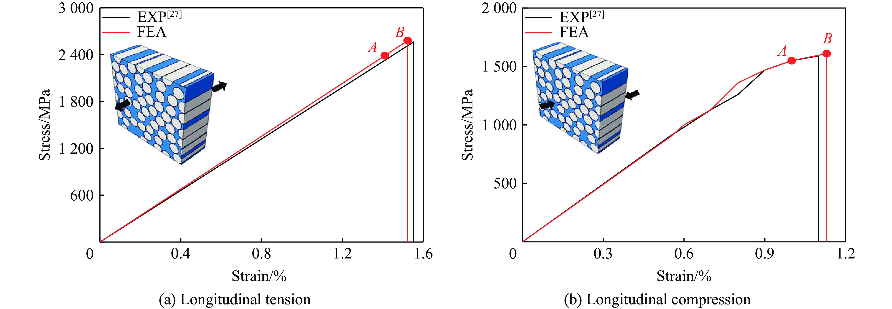
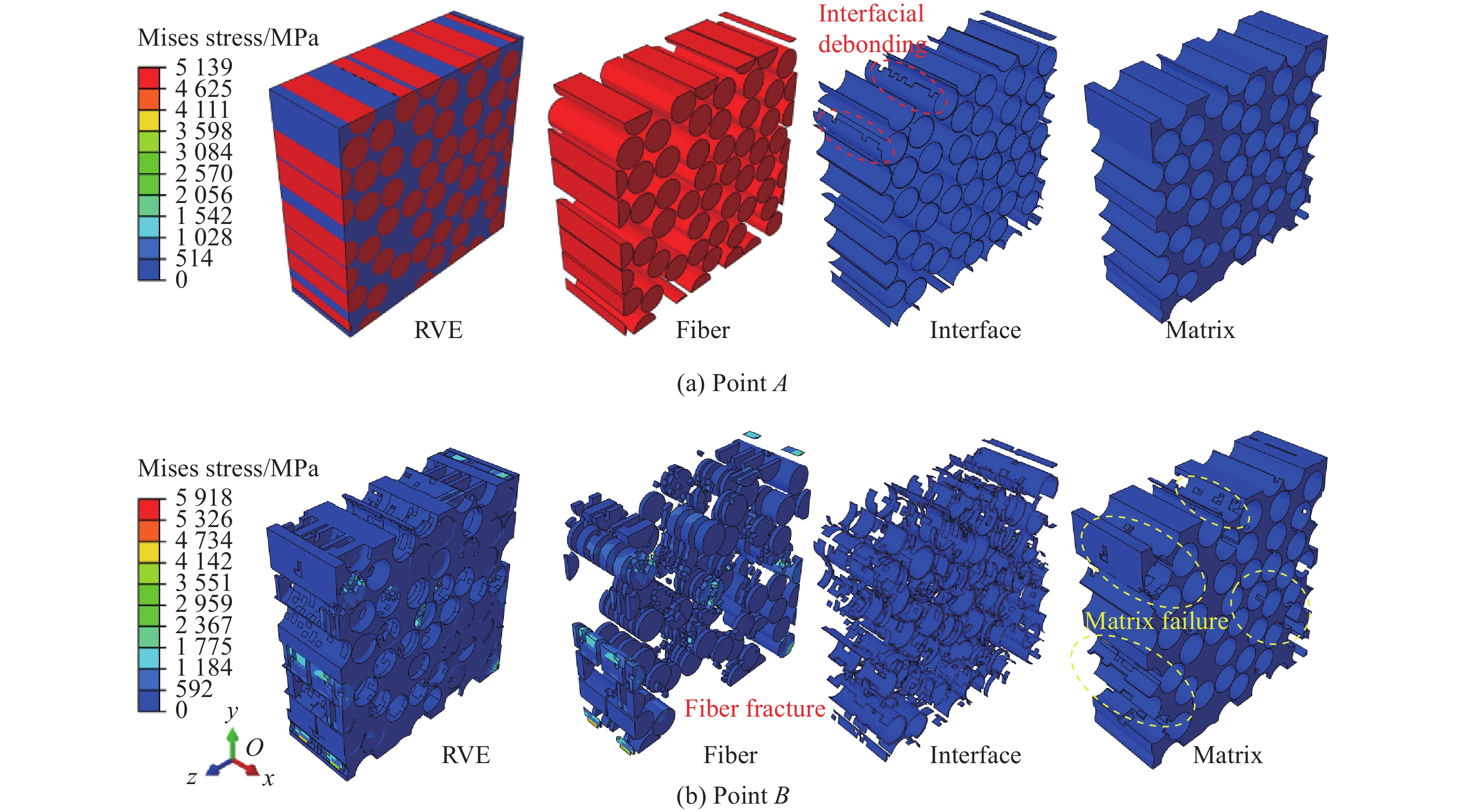

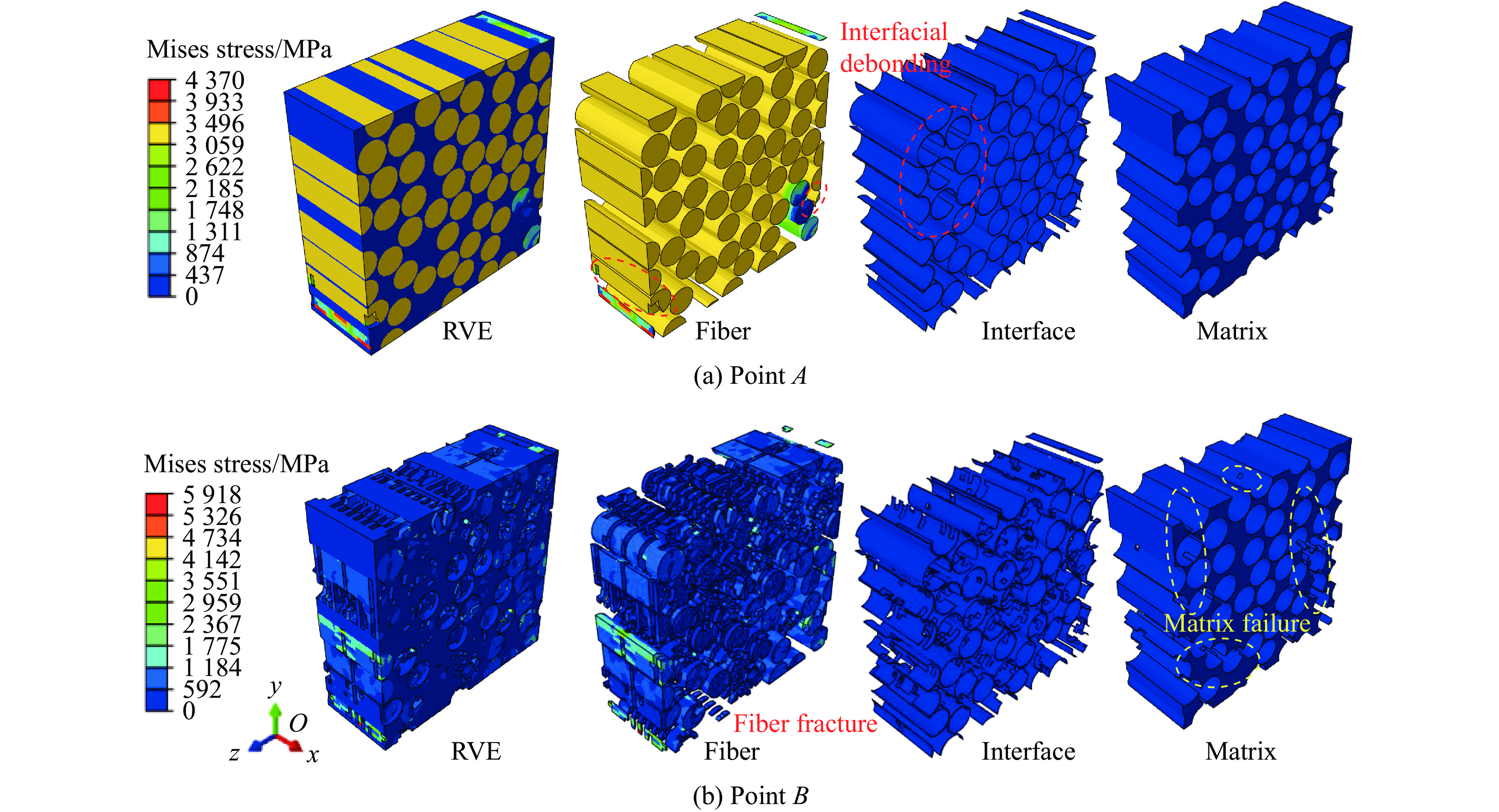
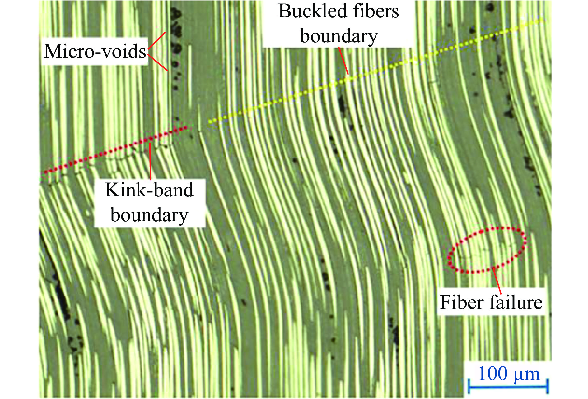
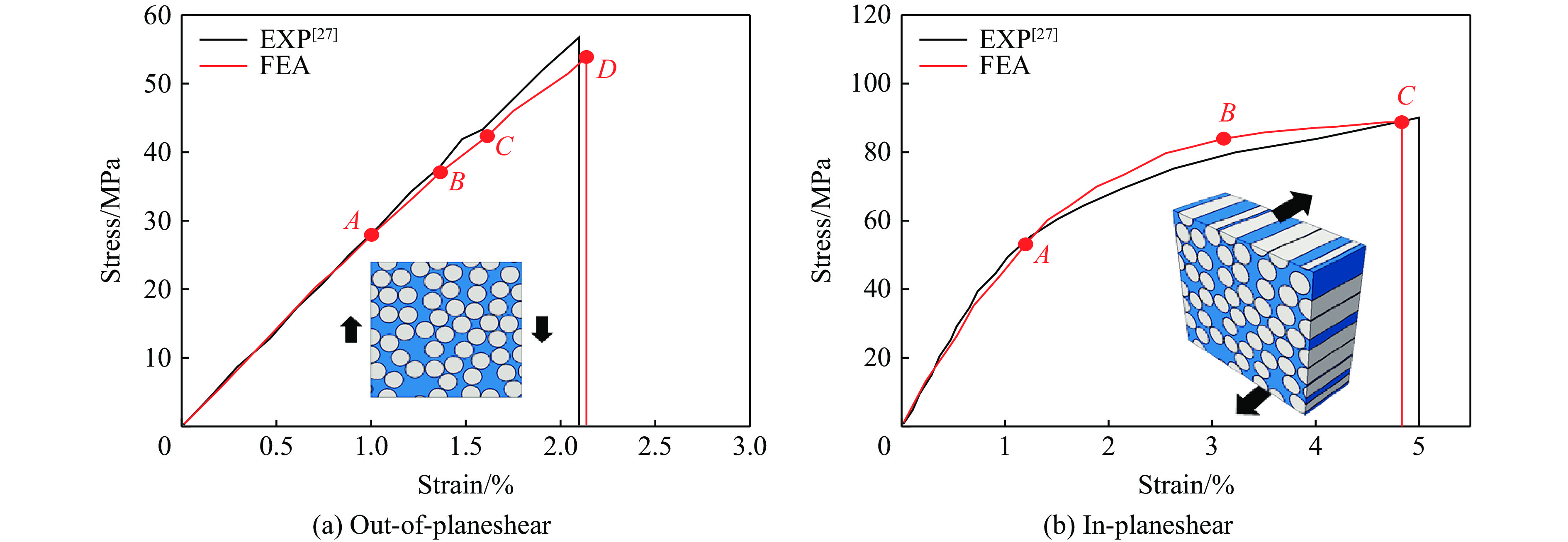
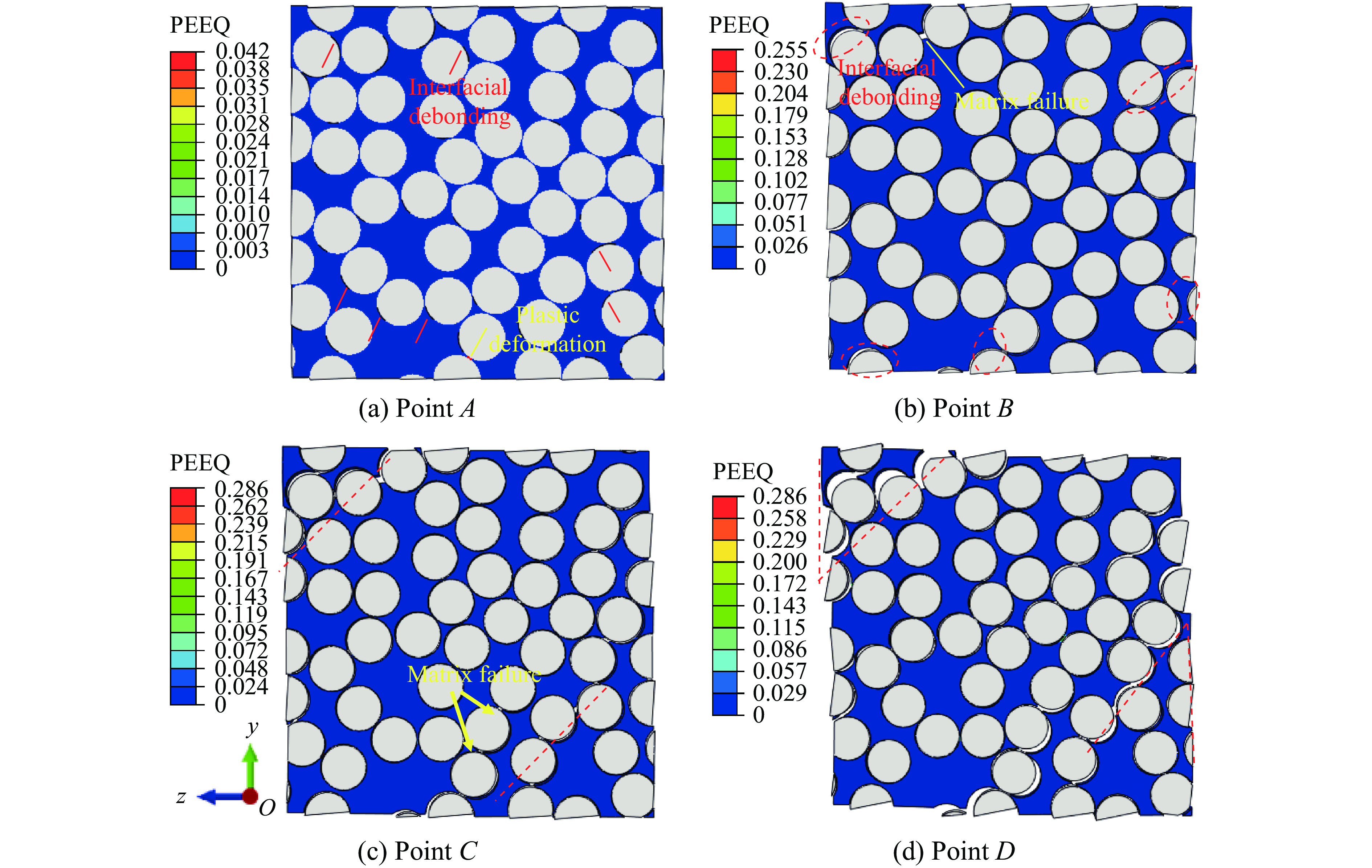
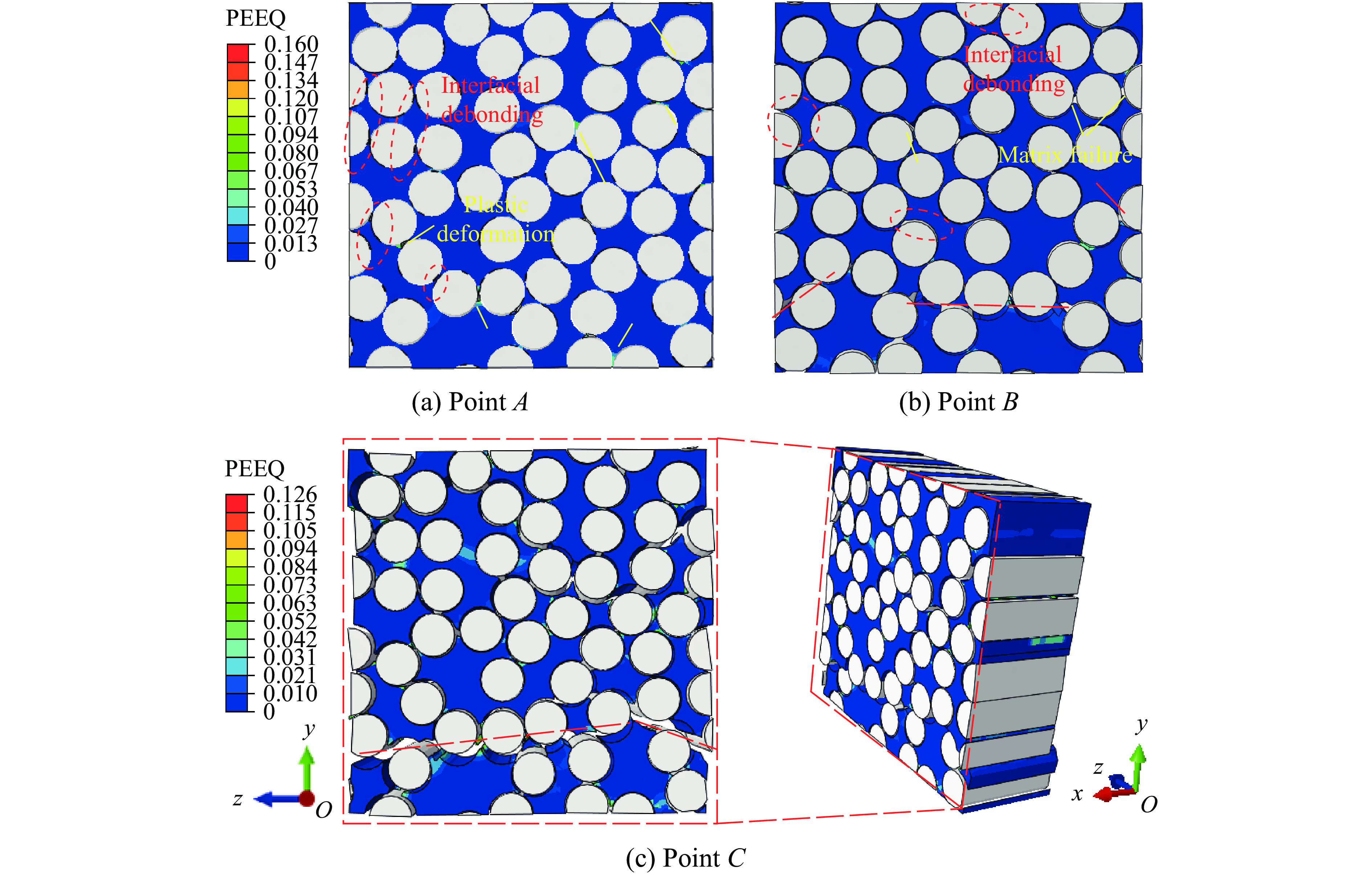
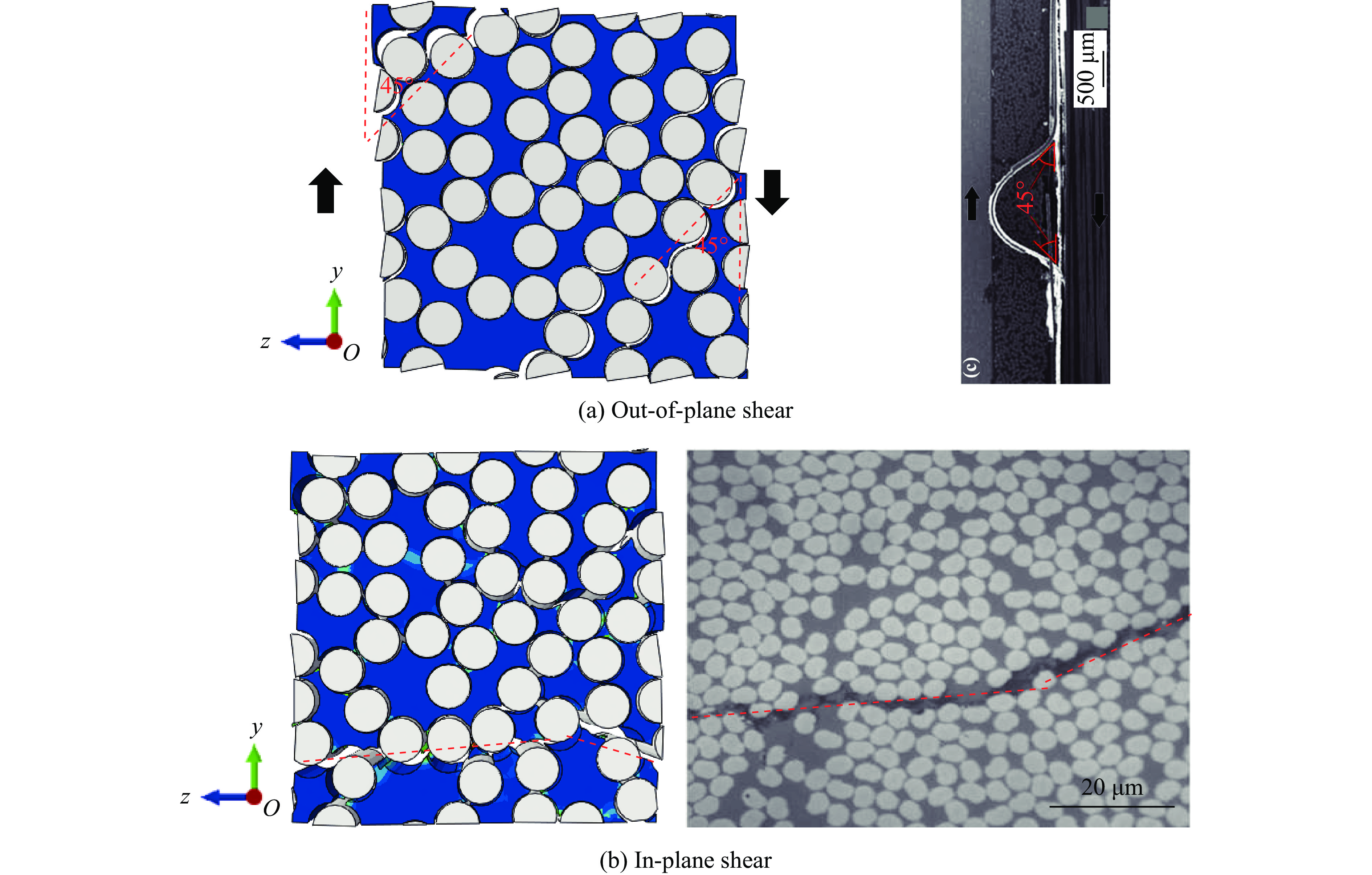
, Available online , doi: 10.11883/bzycj-2025-0216
Abstract:
In order to systematically evaluate the impact safety of human chest impacted by non-lethal kinetic projectiles (NLKP), an integrated three-rib thoracic physical model with a configurable structure was developed, which was compatible with both simulation and experimental testing. The projectile representation was first validated through rigid-wall impacts at 29 m/s and 61 m/s on a controllable gas-launch platform. The measured force–time histories agreed well with the NATO Allied Engineering Publication-99 (AEP-99), corridors, confirming the fidelity of the projectile model. Impact experiments on chest were then conducted using the validated projectile model at 56 m/s and 86.5 m/s. The measured chest-wall displacements and the maximum value of the viscous criterion (VCmax, βvc,max) fell within the validation corridors specified in the AEP-99, demonstrating that the proposed model exhibits dynamic-response consistency and predictive accuracy under medium- and low-velocity impacts at or below 90 m/s. Among them, the maximum relative errors between simulated and experimental displacements at 56 m/s and 86.5 m/s are 16% and 21%, respectively. A projectile hardness scan (soft/medium/hard) showed that VCmax increased from 0.298 m/s to 0.336 m/s at 56 m/s and from 0.765 m/s to 0.856 m/s at 86.5 m/s, indicating a more pronounced risk amplification at higher energies. When the rib spacing varies within the range of 80%−120% of the baseline rib spacing, its effect on the peak displacement and contact force is approximately ±6%, and VCmax fluctuates within 5.7%−6.2%, which is generally within the engineering acceptable range. Compared with the surrogate human thorax for impact model (SHTIM), the proposed model adhered more closely to the corridor mid-line at 56, 86.5 m/s, and yielded VCmax values of 0.308, 0.803 m/s (both within the recommended ranges), whereas the SHTIM slightly underestimated the high-energy case, confirming the model advantage in response fidelity and criterion consistency. A systematic simulation was conducted for impact responses by four typical projectiles (NS, CONDOR, SIR-X, and RB1FS) within the velocity range of 60–90 m/s, elucidating the influence mechanisms of projectile structure and material on thoracic injury risk. Under higher speed impact (100–120 m/s), the soft tissue layer of the model dominates energy absorption and dissipation, while the peak stress in the rib layer increases significantly with velocity and exceeds the yield limit, indicating a high risk of fracture. Thickness sensitivity analysis reveals that the thickness of the soft tissue layer plays the most prominent role in regulating energy absorption and deformation. These findings provide important theoretical and technical support for NLKP impact injury assessment and the optimization of protective equipment.
In order to systematically evaluate the impact safety of human chest impacted by non-lethal kinetic projectiles (NLKP), an integrated three-rib thoracic physical model with a configurable structure was developed, which was compatible with both simulation and experimental testing. The projectile representation was first validated through rigid-wall impacts at 29 m/s and 61 m/s on a controllable gas-launch platform. The measured force–time histories agreed well with the NATO Allied Engineering Publication-99 (AEP-99), corridors, confirming the fidelity of the projectile model. Impact experiments on chest were then conducted using the validated projectile model at 56 m/s and 86.5 m/s. The measured chest-wall displacements and the maximum value of the viscous criterion (VCmax, βvc,max) fell within the validation corridors specified in the AEP-99, demonstrating that the proposed model exhibits dynamic-response consistency and predictive accuracy under medium- and low-velocity impacts at or below 90 m/s. Among them, the maximum relative errors between simulated and experimental displacements at 56 m/s and 86.5 m/s are 16% and 21%, respectively. A projectile hardness scan (soft/medium/hard) showed that VCmax increased from 0.298 m/s to 0.336 m/s at 56 m/s and from 0.765 m/s to 0.856 m/s at 86.5 m/s, indicating a more pronounced risk amplification at higher energies. When the rib spacing varies within the range of 80%−120% of the baseline rib spacing, its effect on the peak displacement and contact force is approximately ±6%, and VCmax fluctuates within 5.7%−6.2%, which is generally within the engineering acceptable range. Compared with the surrogate human thorax for impact model (SHTIM), the proposed model adhered more closely to the corridor mid-line at 56, 86.5 m/s, and yielded VCmax values of 0.308, 0.803 m/s (both within the recommended ranges), whereas the SHTIM slightly underestimated the high-energy case, confirming the model advantage in response fidelity and criterion consistency. A systematic simulation was conducted for impact responses by four typical projectiles (NS, CONDOR, SIR-X, and RB1FS) within the velocity range of 60–90 m/s, elucidating the influence mechanisms of projectile structure and material on thoracic injury risk. Under higher speed impact (100–120 m/s), the soft tissue layer of the model dominates energy absorption and dissipation, while the peak stress in the rib layer increases significantly with velocity and exceeds the yield limit, indicating a high risk of fracture. Thickness sensitivity analysis reveals that the thickness of the soft tissue layer plays the most prominent role in regulating energy absorption and deformation. These findings provide important theoretical and technical support for NLKP impact injury assessment and the optimization of protective equipment.
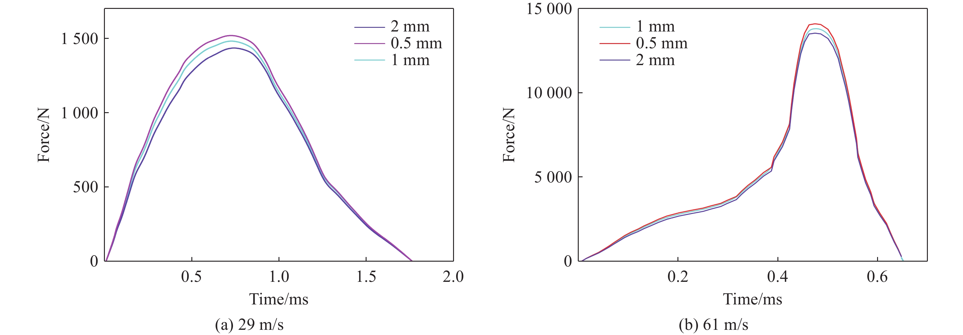
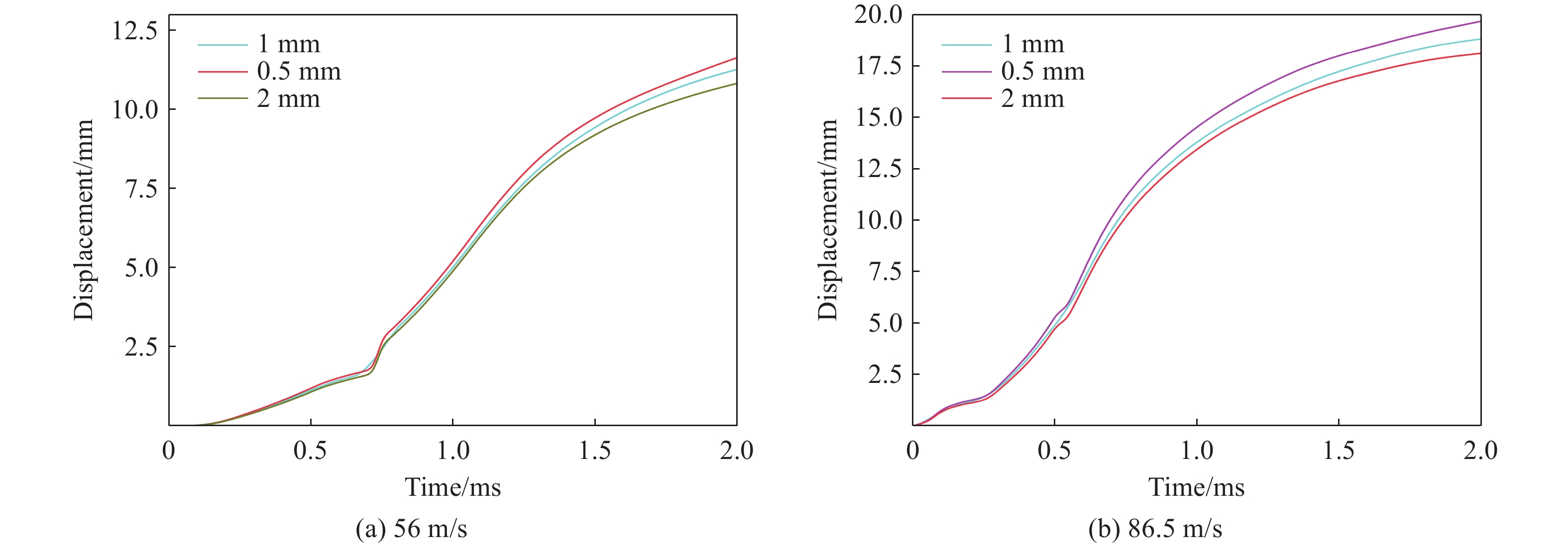
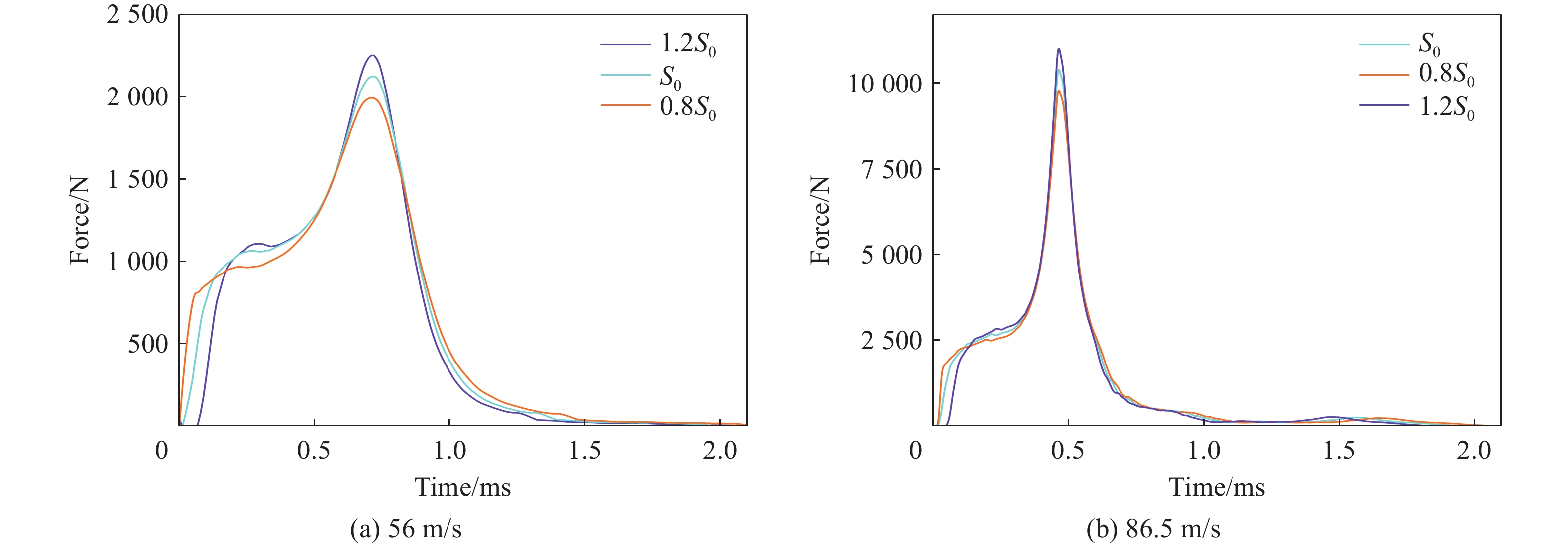
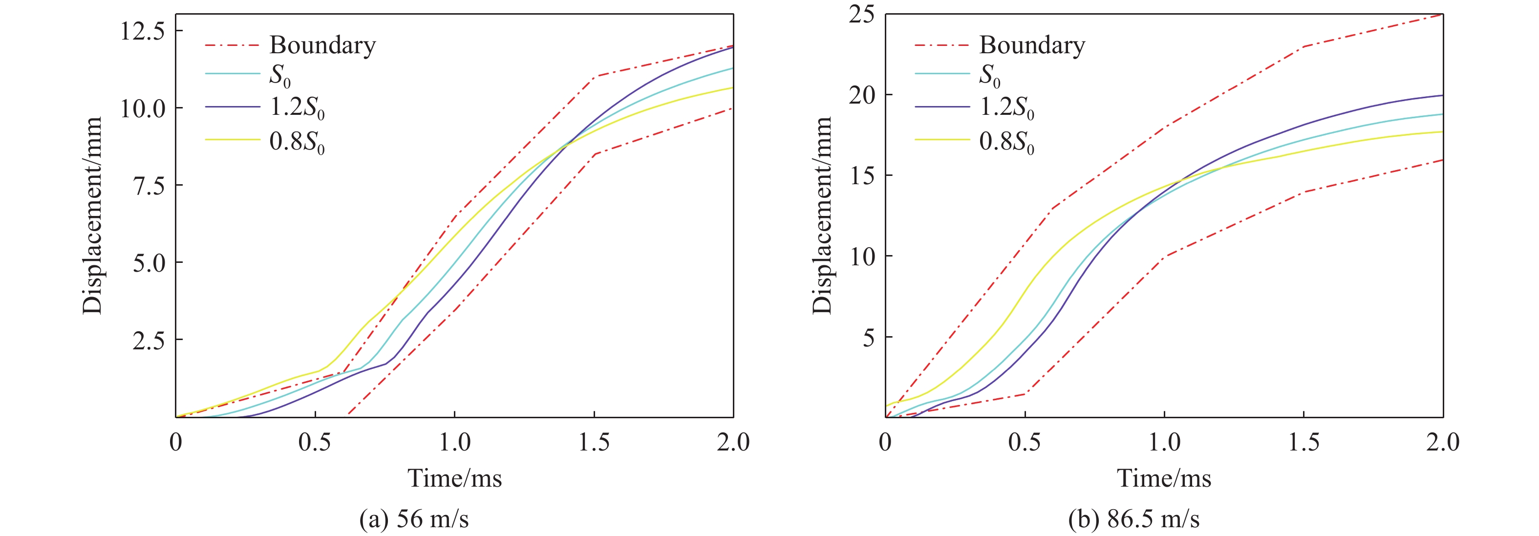
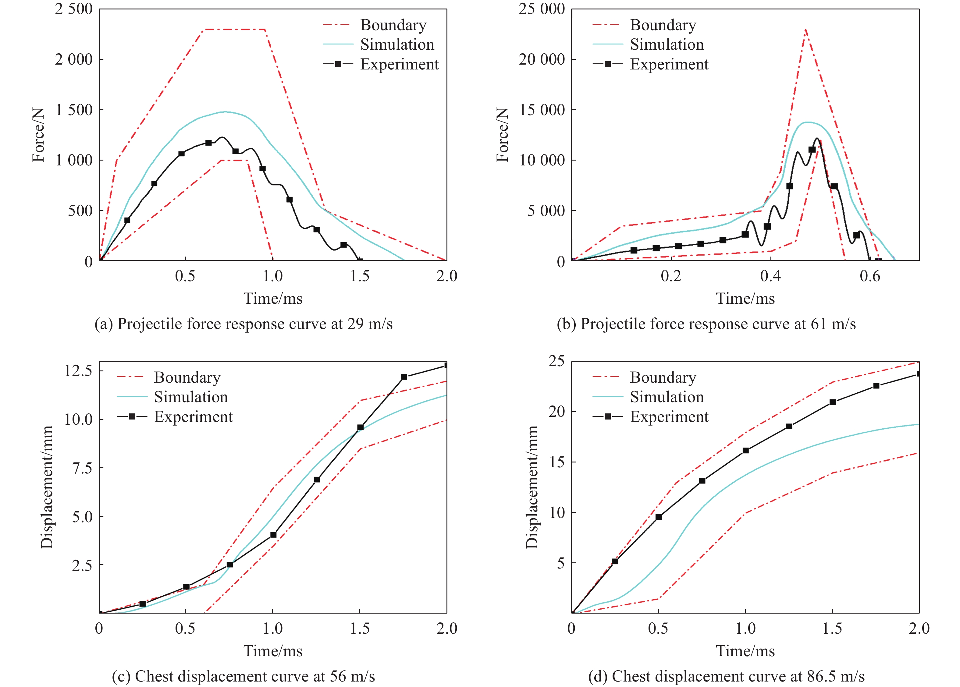
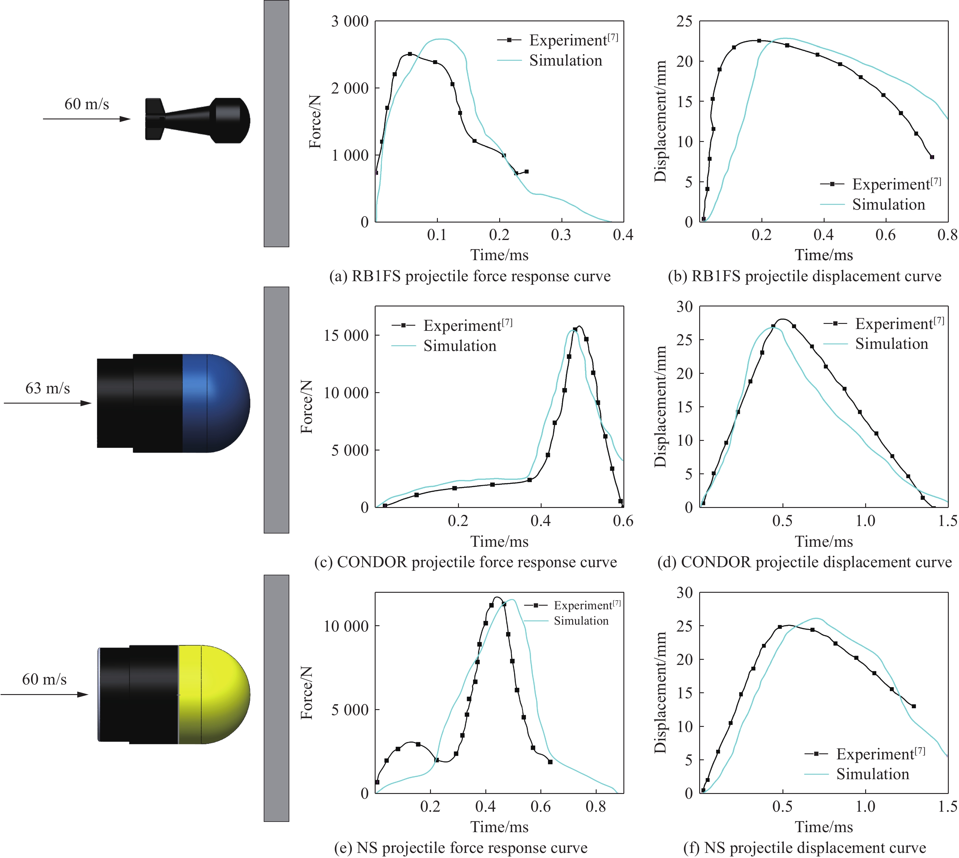
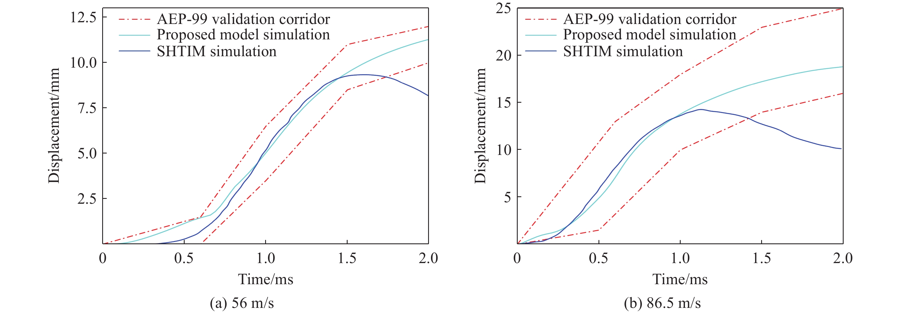
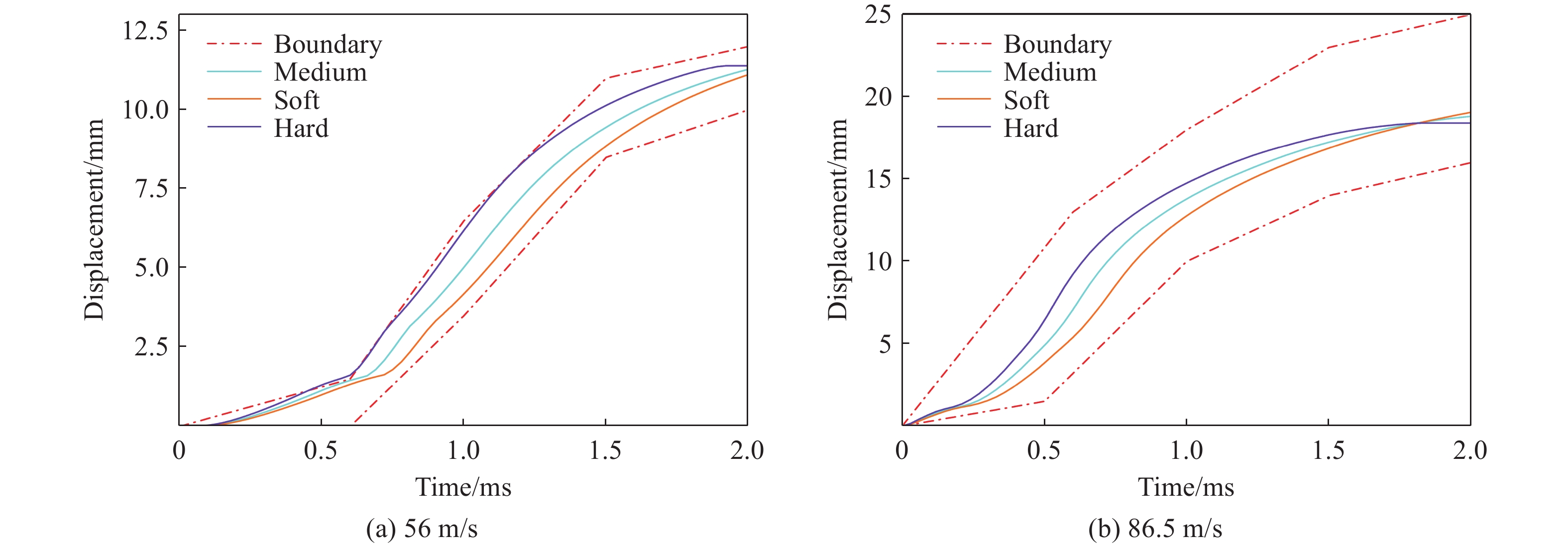
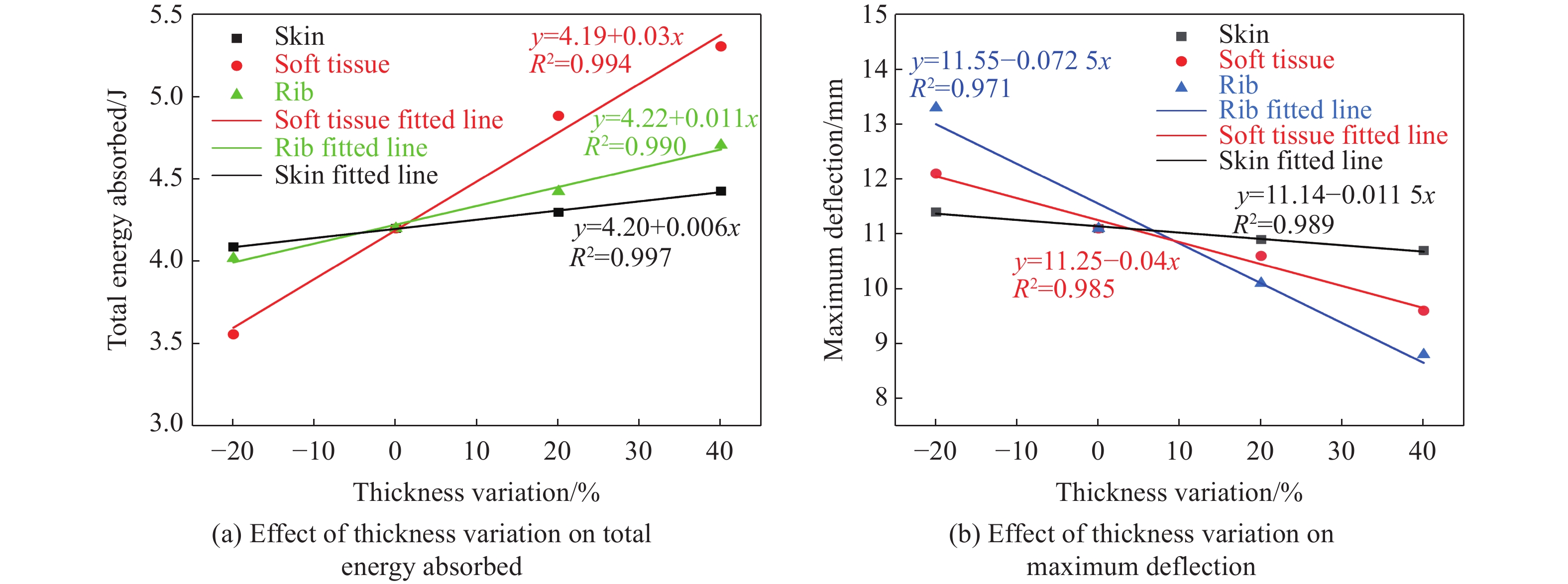
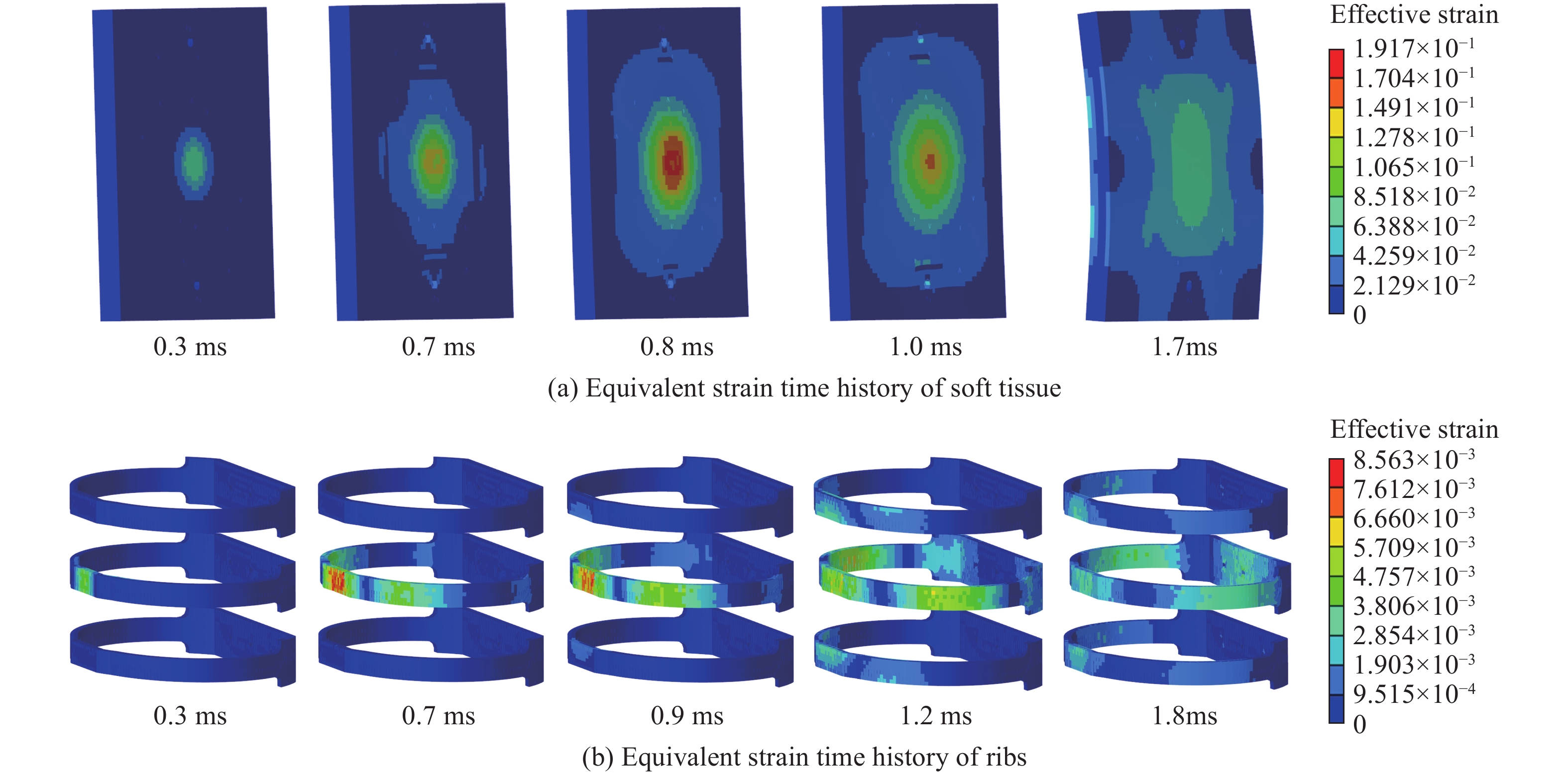
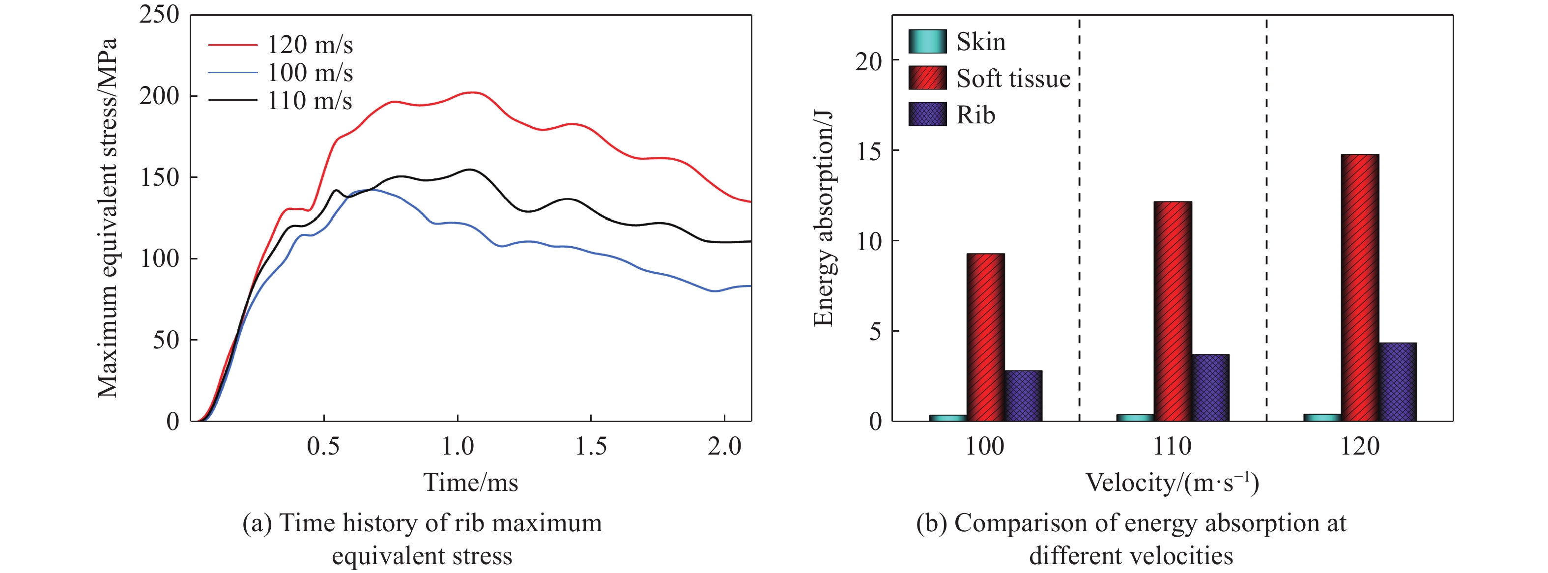
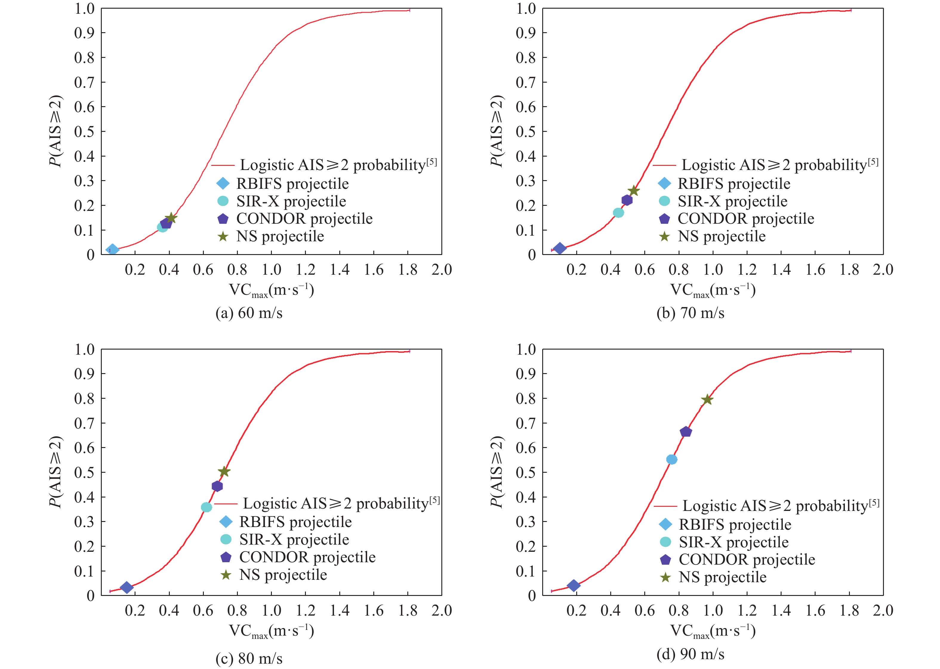
, Available online , doi: 10.11883/bzycj-2025-0219
Abstract:
Deep coal rock blasting poses high risks, and hydraulic fracturing faces limitations, necessitating the development of controllable rock-breaking technologies. As an advanced high-energy gas fracturing technique, high-energy gas-generating agents demonstrate remarkable advantages in rock fragmentation, providing robust technical support for efficient and safe coal mining. This study focuses on the casing materials of high-energy gas-generating agents, investigating their impact on borehole wall pressure during coal rock fracturing. A comprehensive pressure monitoring system was established, employing three casing materials—transparent PVC, white PVC, and kraft paper tubes—for borehole wall pressure experiments. Attenuation indices and reliability were selected as evaluation metrics to analyze the influence of material physical properties on borehole wall pressure. Results indicate that the initiator, upon ignition, generates stress waves and a small amount of gas. The stress wave induces the first pressure peak, followed by a decline due to gas diffusion. The superposition of reflected stress waves and gas expansion waves forms the second peak, while gas expansion variations produce the third peak. Without the main agent, the initiator group exhibits the lowest pressure peak, shortest pressure rise time, minimal loading rate, limited energy release, and low transmission efficiency. For the three groups containing the main agent, pressure peaks near the high-energy gas-generating agent (10 cm away) approximate 200 MPa, with pressure rise times around 20 ms. The attenuation coefficients of pressure peaks for the three casing materials from the biggest to the smallest follow the order: transparent PVC, white PVC, and kraft paper tube. The attenuation coefficients of pressure rise times from the biggest to the smallest rank as: transparent PVC, kraft paper tube, and white PVC. For loading rate attenuation coefficients, the sequence from the biggest to the smallest is: white PVC, transparent PVC, and kraft paper tube. Because of its high elastic modulus and low Poisson’s ratio, white PVC casing demonstrates optimal performance in pressure peak, rise time, and loading rate near the high-energy gas-generating agent, achieving the highest energy transmission efficiency. Transparent PVC casing exhibits higher pressure peaks and loading rates than the paper tube near the agent but underperforms at longer distances, indicating strong directionality and concentration. The kraft paper tube ensures uniform energy distribution but exhibits the weakest overall energy concentration, along with the longest rise times and lowest loading rates. These findings provide a theoretical foundation for optimizing high-energy gas-generating agent designs and enhancing rock-breaking efficacy.
Deep coal rock blasting poses high risks, and hydraulic fracturing faces limitations, necessitating the development of controllable rock-breaking technologies. As an advanced high-energy gas fracturing technique, high-energy gas-generating agents demonstrate remarkable advantages in rock fragmentation, providing robust technical support for efficient and safe coal mining. This study focuses on the casing materials of high-energy gas-generating agents, investigating their impact on borehole wall pressure during coal rock fracturing. A comprehensive pressure monitoring system was established, employing three casing materials—transparent PVC, white PVC, and kraft paper tubes—for borehole wall pressure experiments. Attenuation indices and reliability were selected as evaluation metrics to analyze the influence of material physical properties on borehole wall pressure. Results indicate that the initiator, upon ignition, generates stress waves and a small amount of gas. The stress wave induces the first pressure peak, followed by a decline due to gas diffusion. The superposition of reflected stress waves and gas expansion waves forms the second peak, while gas expansion variations produce the third peak. Without the main agent, the initiator group exhibits the lowest pressure peak, shortest pressure rise time, minimal loading rate, limited energy release, and low transmission efficiency. For the three groups containing the main agent, pressure peaks near the high-energy gas-generating agent (10 cm away) approximate 200 MPa, with pressure rise times around 20 ms. The attenuation coefficients of pressure peaks for the three casing materials from the biggest to the smallest follow the order: transparent PVC, white PVC, and kraft paper tube. The attenuation coefficients of pressure rise times from the biggest to the smallest rank as: transparent PVC, kraft paper tube, and white PVC. For loading rate attenuation coefficients, the sequence from the biggest to the smallest is: white PVC, transparent PVC, and kraft paper tube. Because of its high elastic modulus and low Poisson’s ratio, white PVC casing demonstrates optimal performance in pressure peak, rise time, and loading rate near the high-energy gas-generating agent, achieving the highest energy transmission efficiency. Transparent PVC casing exhibits higher pressure peaks and loading rates than the paper tube near the agent but underperforms at longer distances, indicating strong directionality and concentration. The kraft paper tube ensures uniform energy distribution but exhibits the weakest overall energy concentration, along with the longest rise times and lowest loading rates. These findings provide a theoretical foundation for optimizing high-energy gas-generating agent designs and enhancing rock-breaking efficacy.
, Available online , doi: 10.11883/bzycj-2025-0140
Abstract:
Hydrogen energy, as a zero-carbon energy source, holds broad application prospects in critical defense systems because of its high energy density and zero carbon emissions. To enhance energy utilization efficiency and ensure operational safety, an integrated approach combining experimental and numerical simulations was adopted to systematically examine the effects of hydrogen concentration on explosion dynamics in a confined space. Experiments were carried out in a cylindrical chamber equipped with high-frequency pressure sensors and a high-speed camera to record transient overpressure and track flame propagation behavior. Complementing the experimental setup, computational fluid dynamics (CFD) simulations were implemented using a detailed 19-step hydrogen/air chemical reaction mechanism to accurately reproduce the spatiotemporal evolution of flow field velocity during the premixed gas explosion process. Results indicate that the maximum explosion pressure occurred at a hydrogen volume fraction of 30%, peaking at 0.623 94 MPa. The peak flame area was largest at both 30% and 45%, exceeding results at 15% and 60% by 14.6% and 6.3%, respectively. The 30 % condition also achieved the peak flame area in the shortest time, at 8.2 ms. Furthermore, geometric constraints at the junction of the cylindrical sidewall and the endwall led to accumulation of unburned hydrogen, causing localized increases in density and pressure and resulting in four clearly discernible high-velocity regions within the flow field. At 9 ms, the flow velocity profile along the centerline exhibited symmetry with a dual-peak structure appearing unilaterally. While the 45% condition showed an early transient velocity advantage due to intensified local heat release, the 30% condition demonstrated superior late-stage velocity recovery owing to more stable and sustained combustion near the stoichiometric ratio. These findings underscore the high combustion efficiency and stability achievable near stoichiometric conditions, providing a scientific foundation for the design and optimization of high-efficiency hydrogen combustion systems..
Hydrogen energy, as a zero-carbon energy source, holds broad application prospects in critical defense systems because of its high energy density and zero carbon emissions. To enhance energy utilization efficiency and ensure operational safety, an integrated approach combining experimental and numerical simulations was adopted to systematically examine the effects of hydrogen concentration on explosion dynamics in a confined space. Experiments were carried out in a cylindrical chamber equipped with high-frequency pressure sensors and a high-speed camera to record transient overpressure and track flame propagation behavior. Complementing the experimental setup, computational fluid dynamics (CFD) simulations were implemented using a detailed 19-step hydrogen/air chemical reaction mechanism to accurately reproduce the spatiotemporal evolution of flow field velocity during the premixed gas explosion process. Results indicate that the maximum explosion pressure occurred at a hydrogen volume fraction of 30%, peaking at 0.623 94 MPa. The peak flame area was largest at both 30% and 45%, exceeding results at 15% and 60% by 14.6% and 6.3%, respectively. The 30 % condition also achieved the peak flame area in the shortest time, at 8.2 ms. Furthermore, geometric constraints at the junction of the cylindrical sidewall and the endwall led to accumulation of unburned hydrogen, causing localized increases in density and pressure and resulting in four clearly discernible high-velocity regions within the flow field. At 9 ms, the flow velocity profile along the centerline exhibited symmetry with a dual-peak structure appearing unilaterally. While the 45% condition showed an early transient velocity advantage due to intensified local heat release, the 30% condition demonstrated superior late-stage velocity recovery owing to more stable and sustained combustion near the stoichiometric ratio. These findings underscore the high combustion efficiency and stability achievable near stoichiometric conditions, providing a scientific foundation for the design and optimization of high-efficiency hydrogen combustion systems..
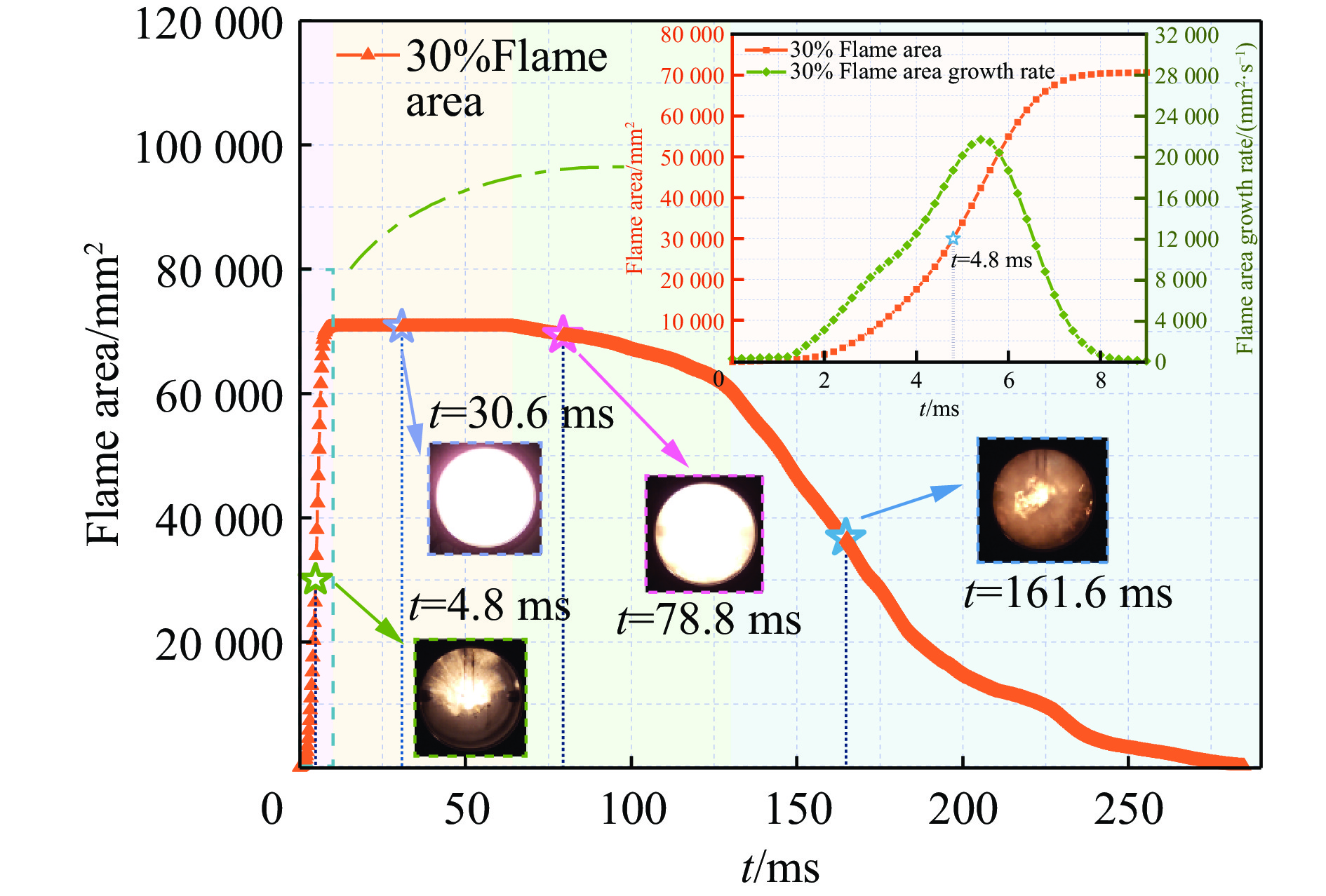
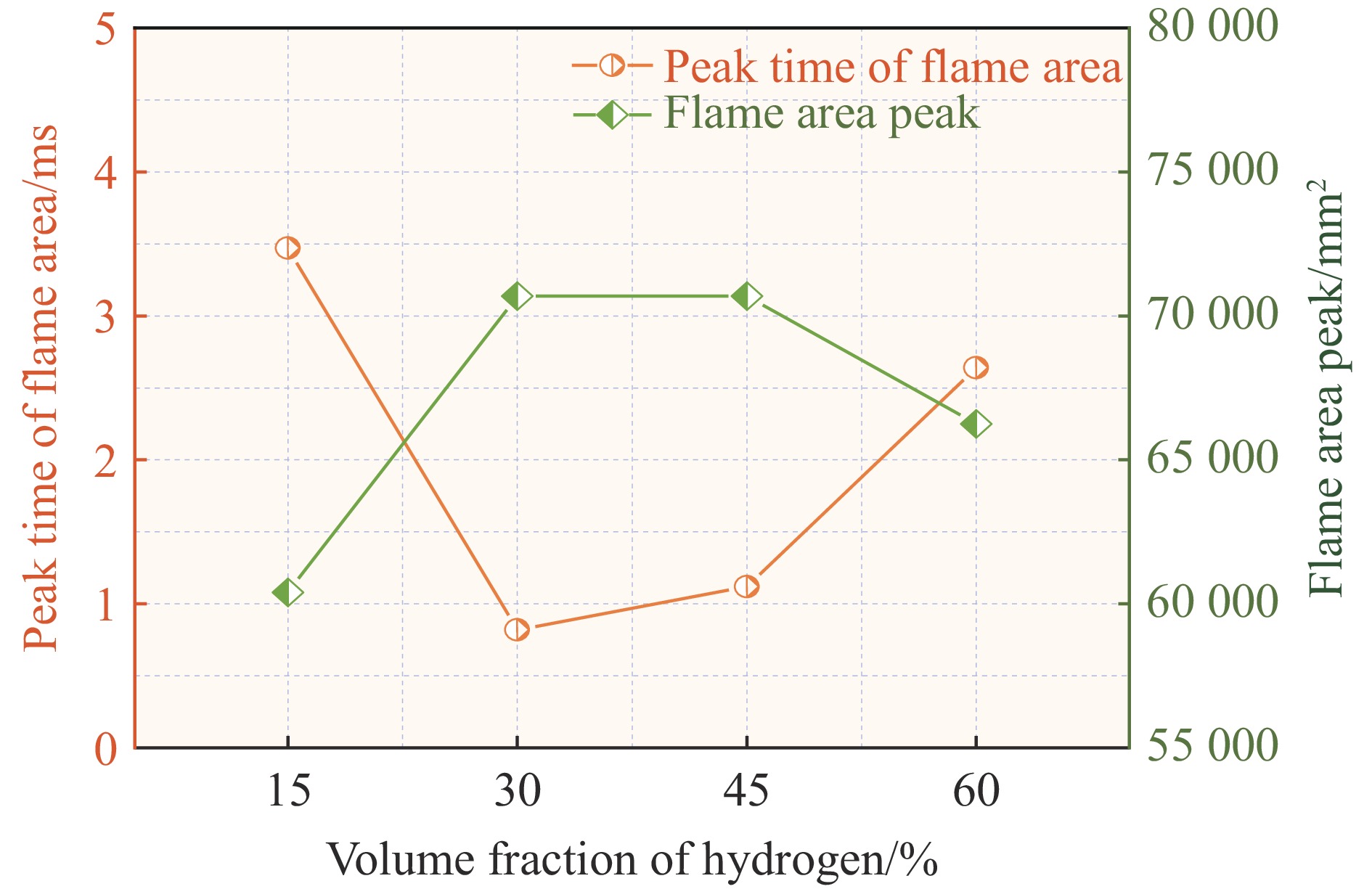
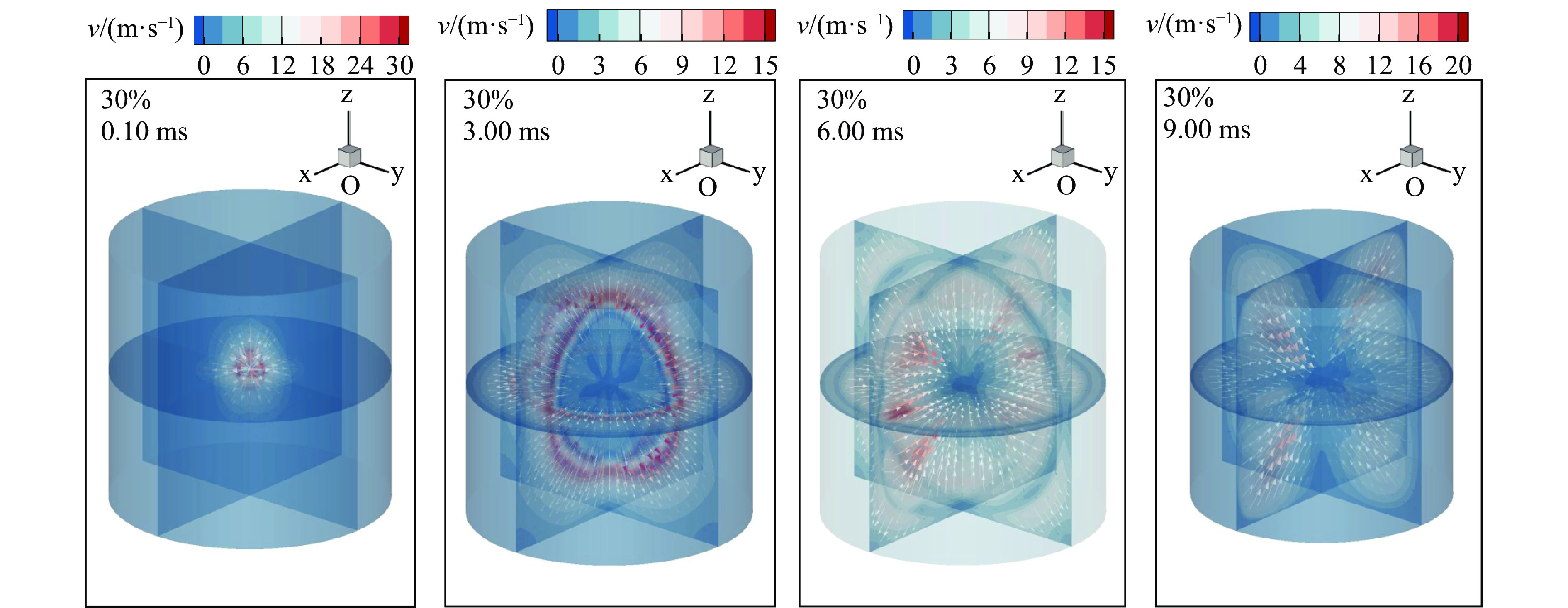
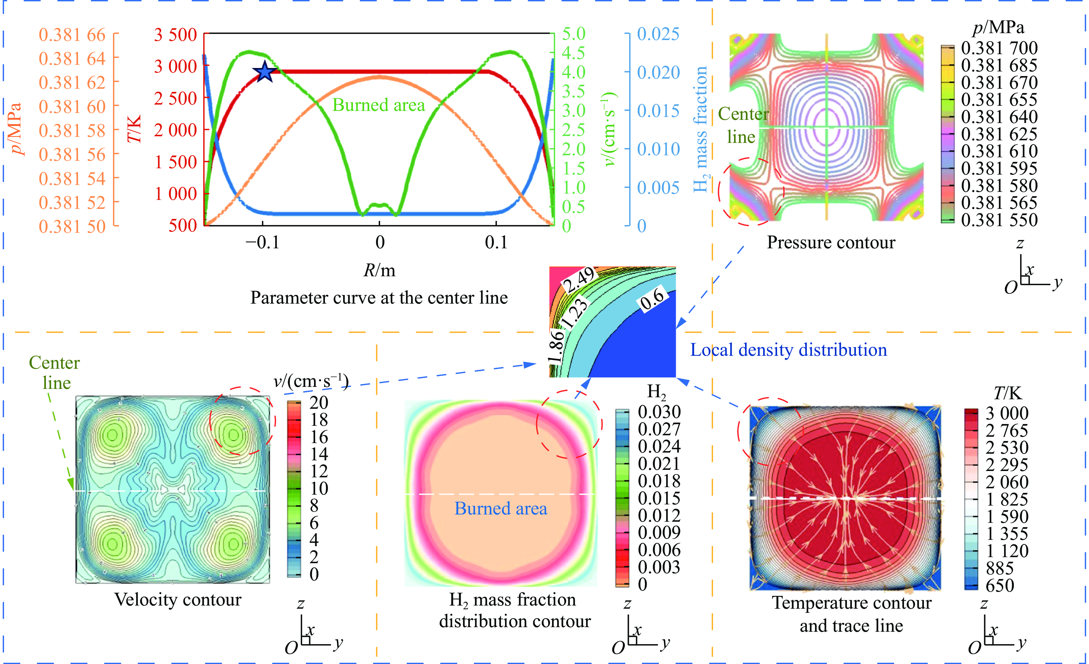
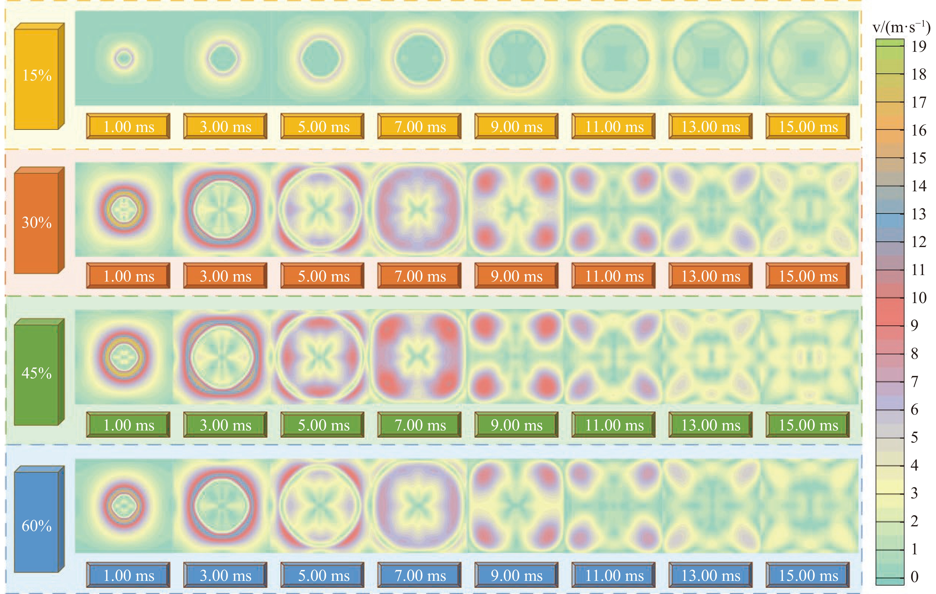
, Available online , doi: 10.11883/bzycj-2025-0301
Abstract:
Nuclear-grade stainless steel Z2CN18.10 is widely used in nuclear power plant piping systems. Its dynamic mechanical behavior under combined high strain rates and elevated temperatures is of great significance for assessing structural integrity under impact loads. To accurately characterize the mechanical behavior of Z2CN18.10 under dynamic loading, quasi-static and high-strain-rate tensile tests were conducted using a universal electronic testing machine and a conventional split Hopkinson tension bar system. The stress-strain responses of the material were obtained within temperature ranges from ambient (25 ℃) up to 400 ℃ and strain rates from 10−3 to 103 s−1. To overcome the limitation of conventional Hopkinson bar apparatus in achieving large-strain loading, an electromagnetically driven bidirectional Hopkinson tension bar system was employed to measure the failure strain of the material under different stress triaxialities. Based on the experimental data, parameters for the Johnson-Cook constitutive model and failure criterion were fitted, and the validity of the model was verified through high-speed impact tests using a gas gun. The results show that the differences between numerical simulations and experiments in terms of perforation diameter, peak strain, and support reaction force were 4.4%, 7.5%, and 2.3%, respectively, indicating good agreement. The established reliable dynamic constitutive model and failure criterion for Z2CN18.10 stainless steel provide an important methodological and data foundation for the impact-resistant design and safety assessment of nuclear power piping systems.
Nuclear-grade stainless steel Z2CN18.10 is widely used in nuclear power plant piping systems. Its dynamic mechanical behavior under combined high strain rates and elevated temperatures is of great significance for assessing structural integrity under impact loads. To accurately characterize the mechanical behavior of Z2CN18.10 under dynamic loading, quasi-static and high-strain-rate tensile tests were conducted using a universal electronic testing machine and a conventional split Hopkinson tension bar system. The stress-strain responses of the material were obtained within temperature ranges from ambient (25 ℃) up to 400 ℃ and strain rates from 10−3 to 103 s−1. To overcome the limitation of conventional Hopkinson bar apparatus in achieving large-strain loading, an electromagnetically driven bidirectional Hopkinson tension bar system was employed to measure the failure strain of the material under different stress triaxialities. Based on the experimental data, parameters for the Johnson-Cook constitutive model and failure criterion were fitted, and the validity of the model was verified through high-speed impact tests using a gas gun. The results show that the differences between numerical simulations and experiments in terms of perforation diameter, peak strain, and support reaction force were 4.4%, 7.5%, and 2.3%, respectively, indicating good agreement. The established reliable dynamic constitutive model and failure criterion for Z2CN18.10 stainless steel provide an important methodological and data foundation for the impact-resistant design and safety assessment of nuclear power piping systems.
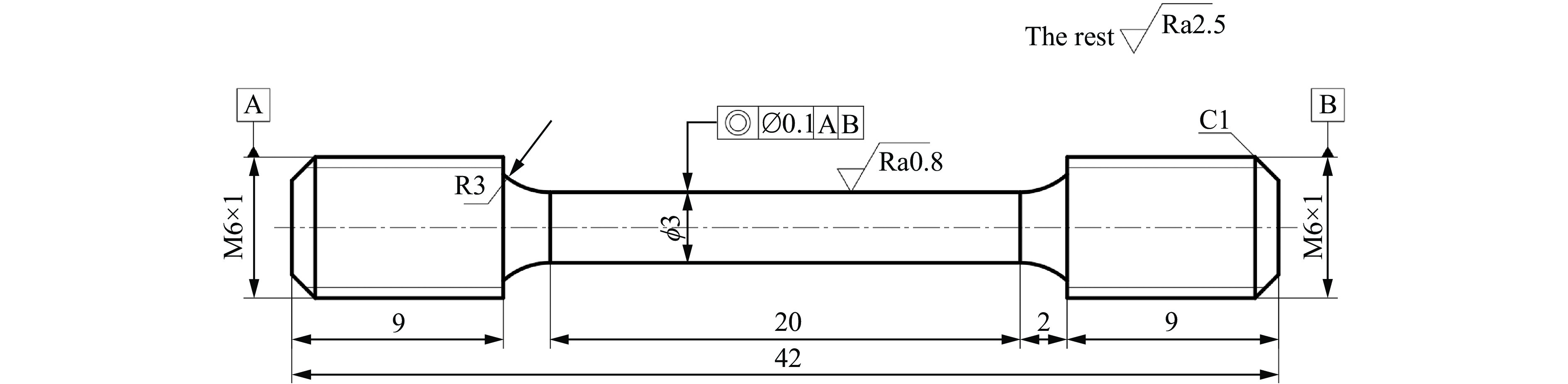
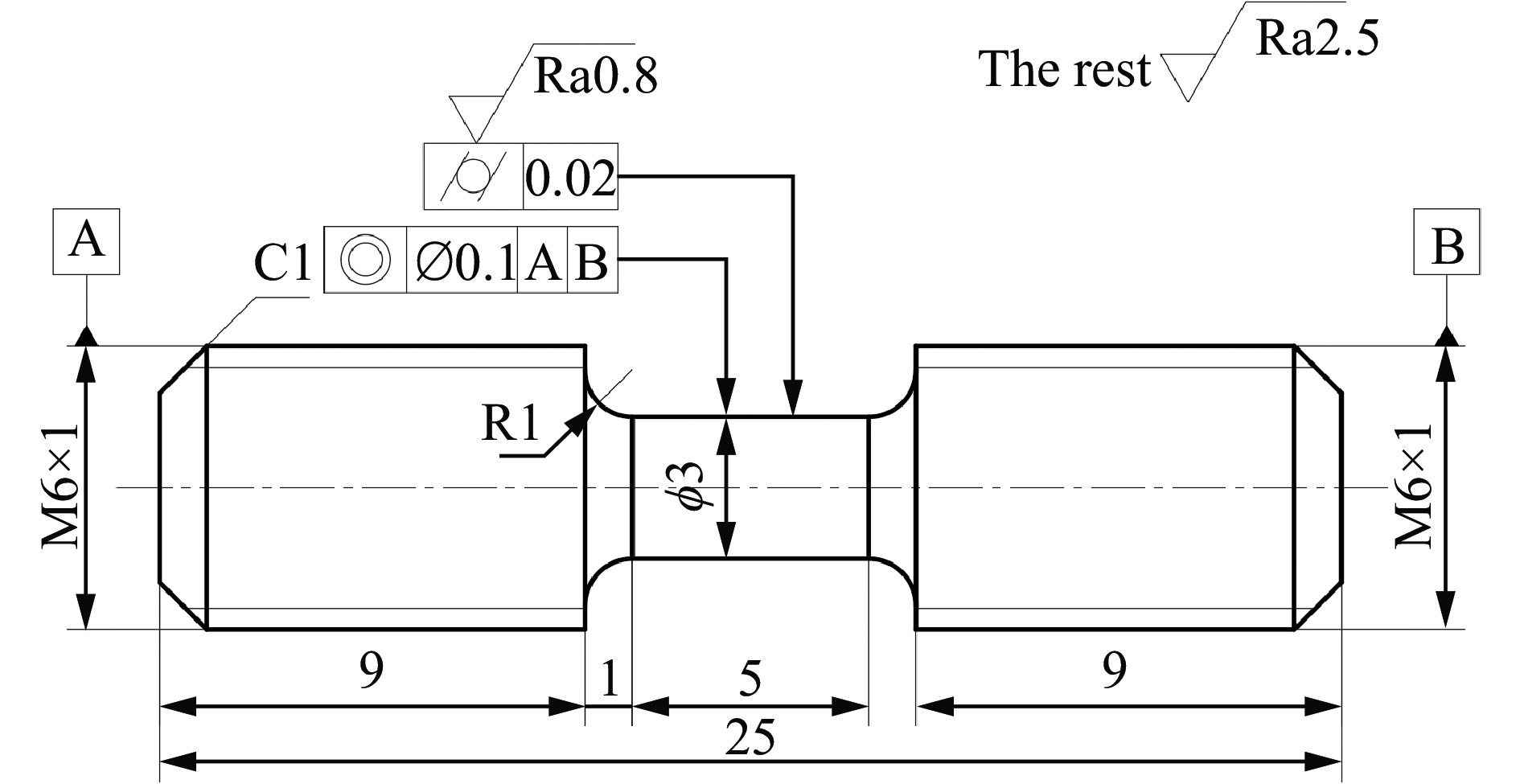
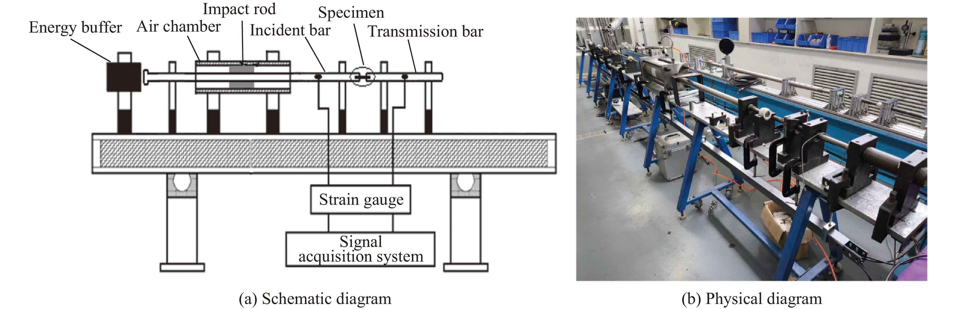
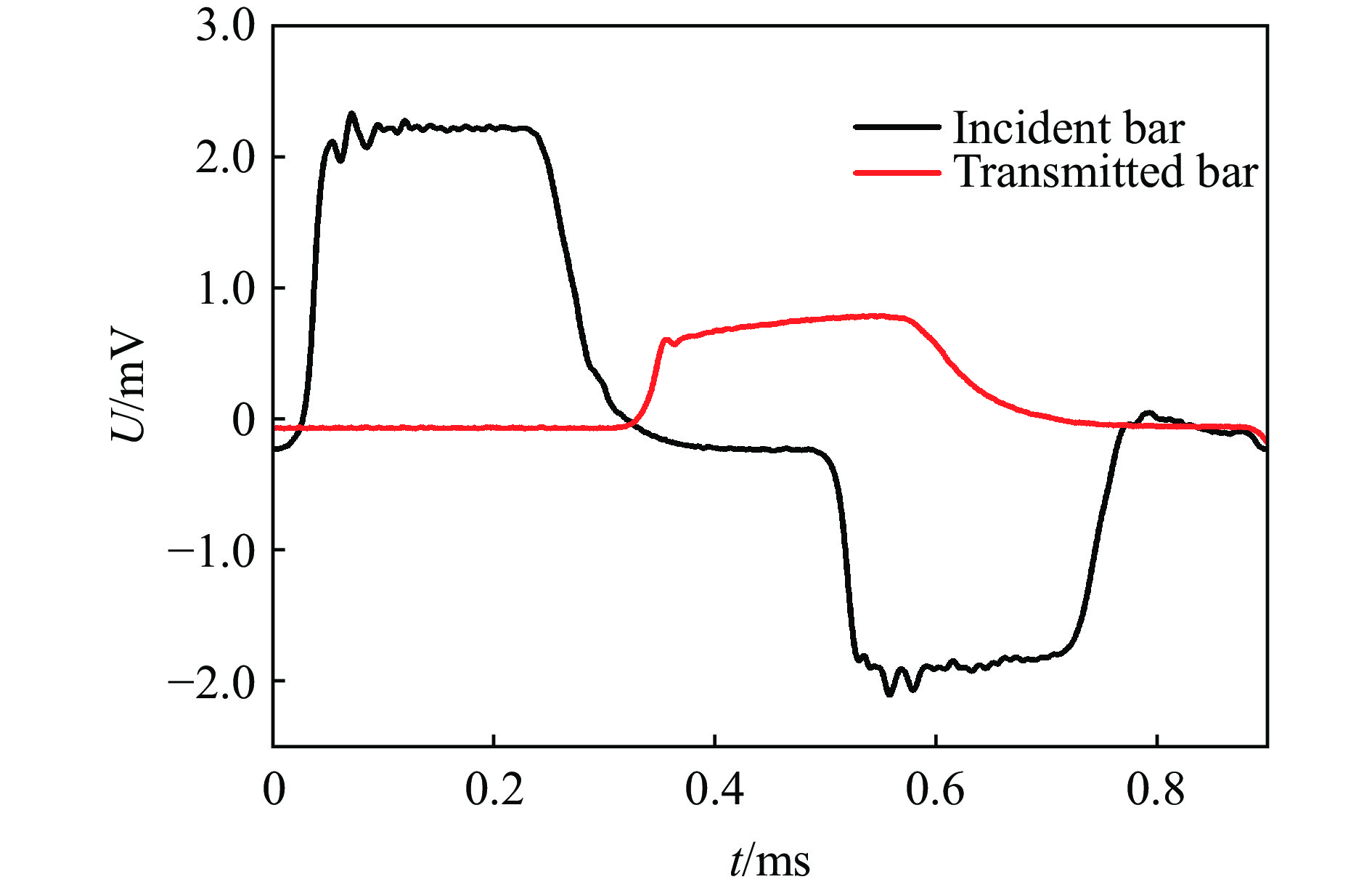
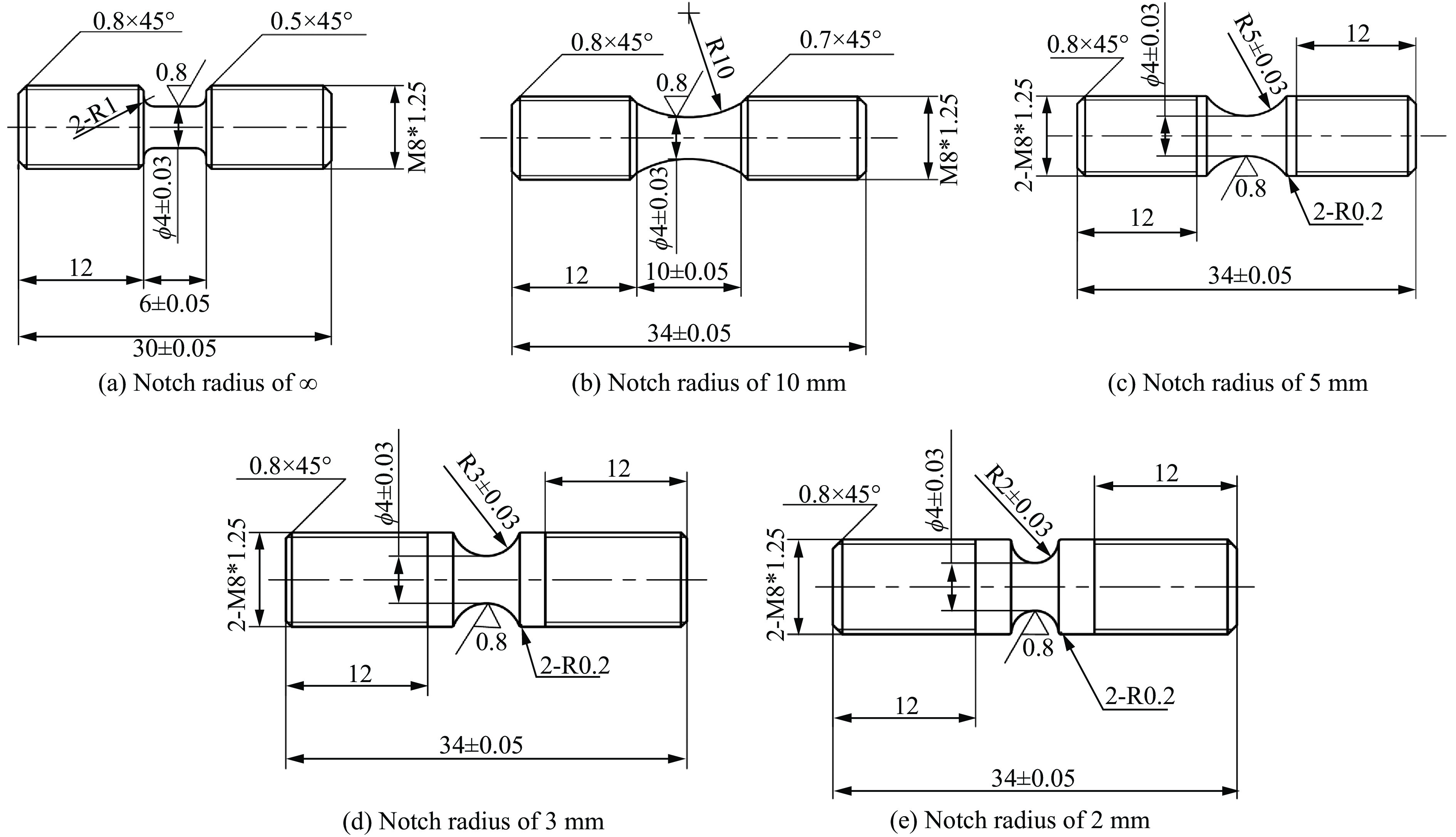
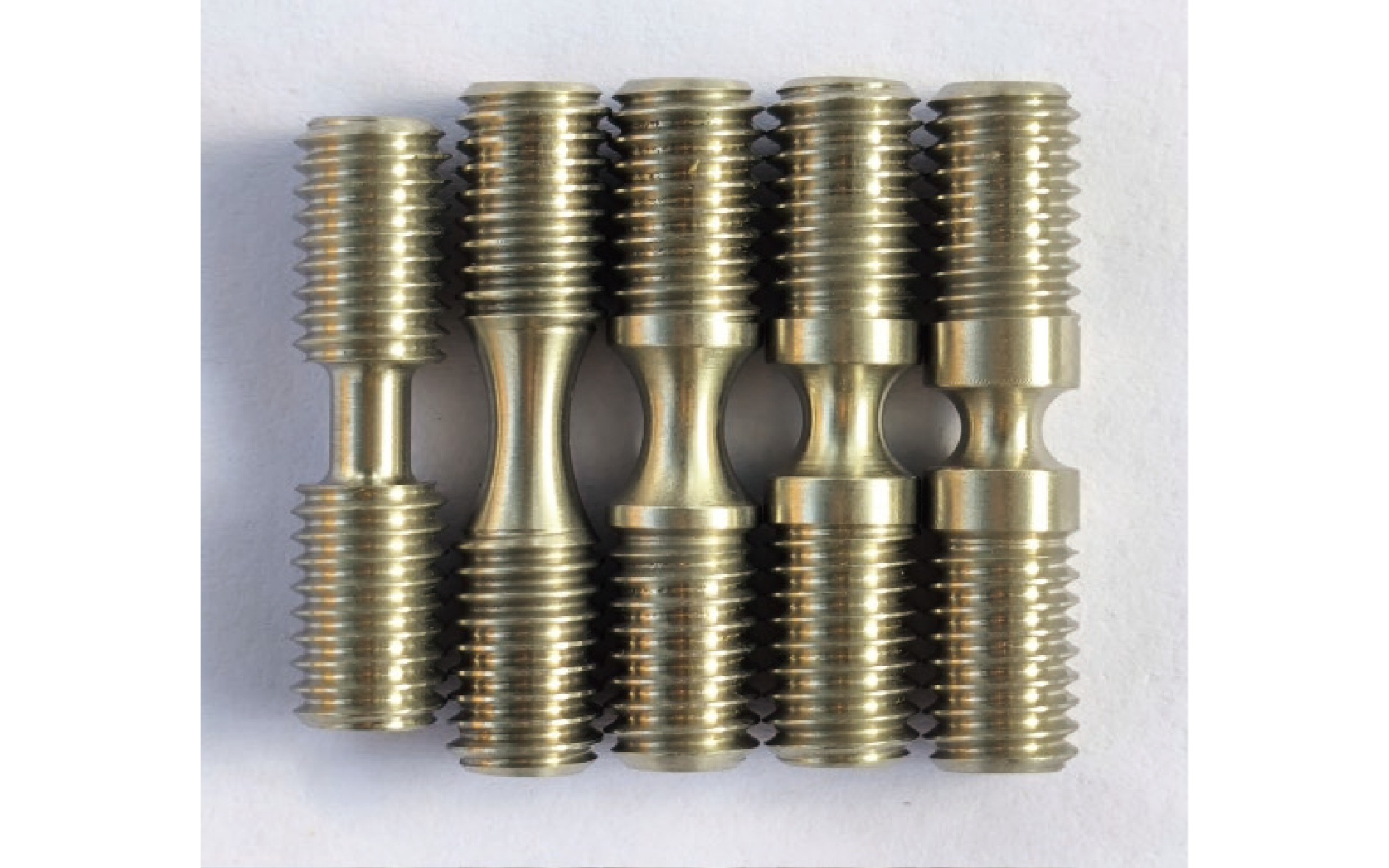
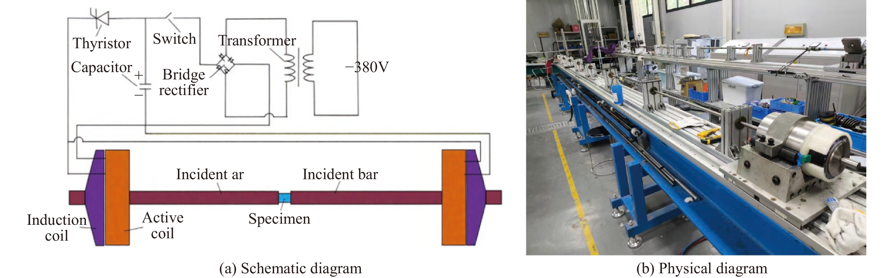
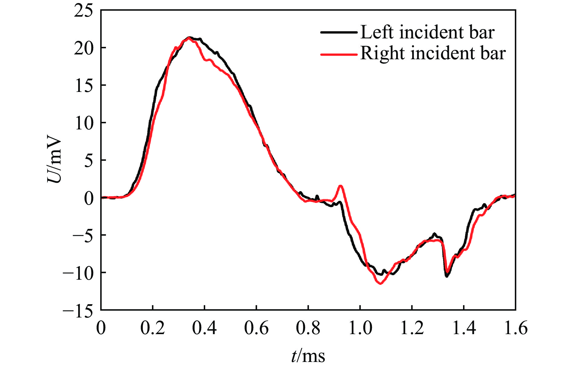
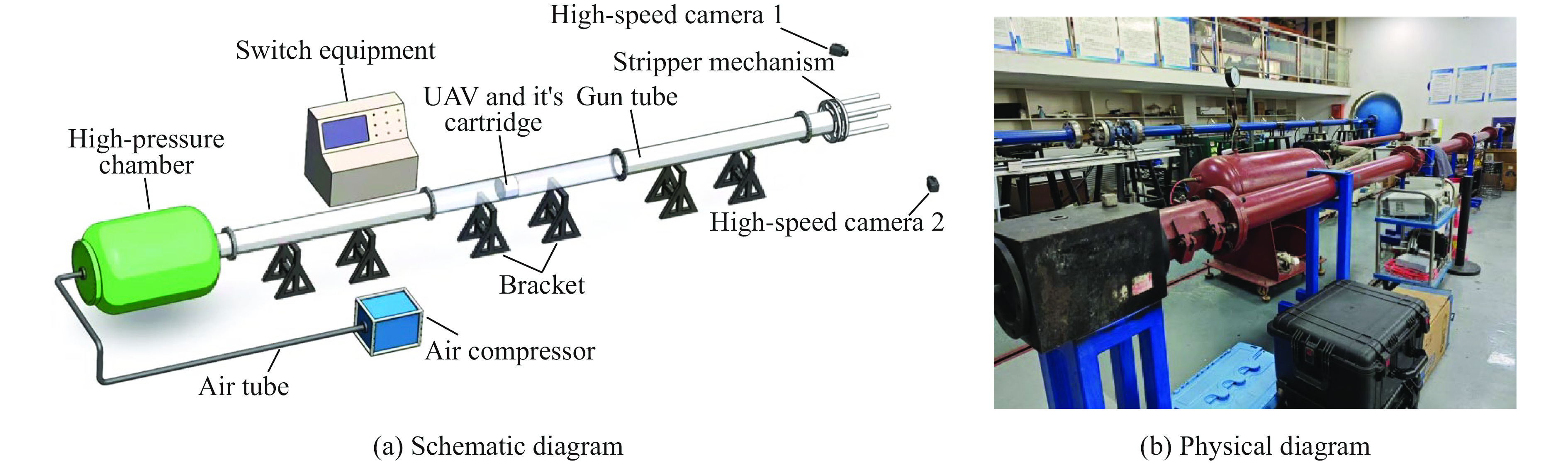
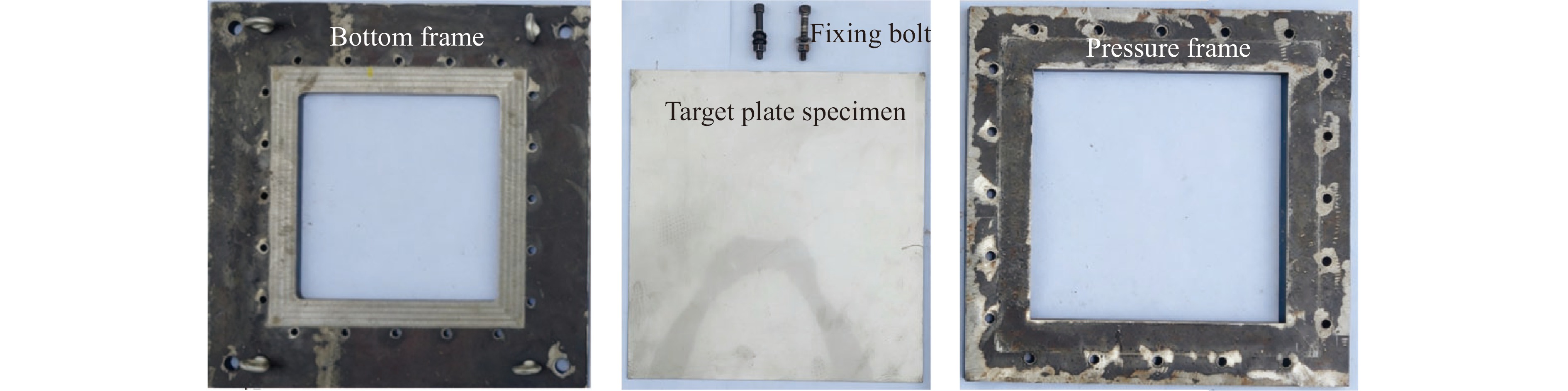
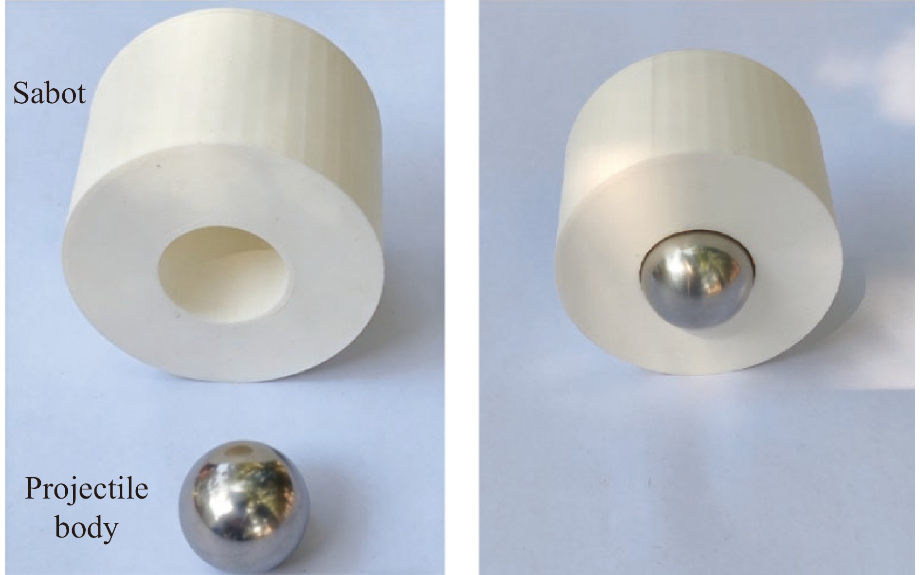
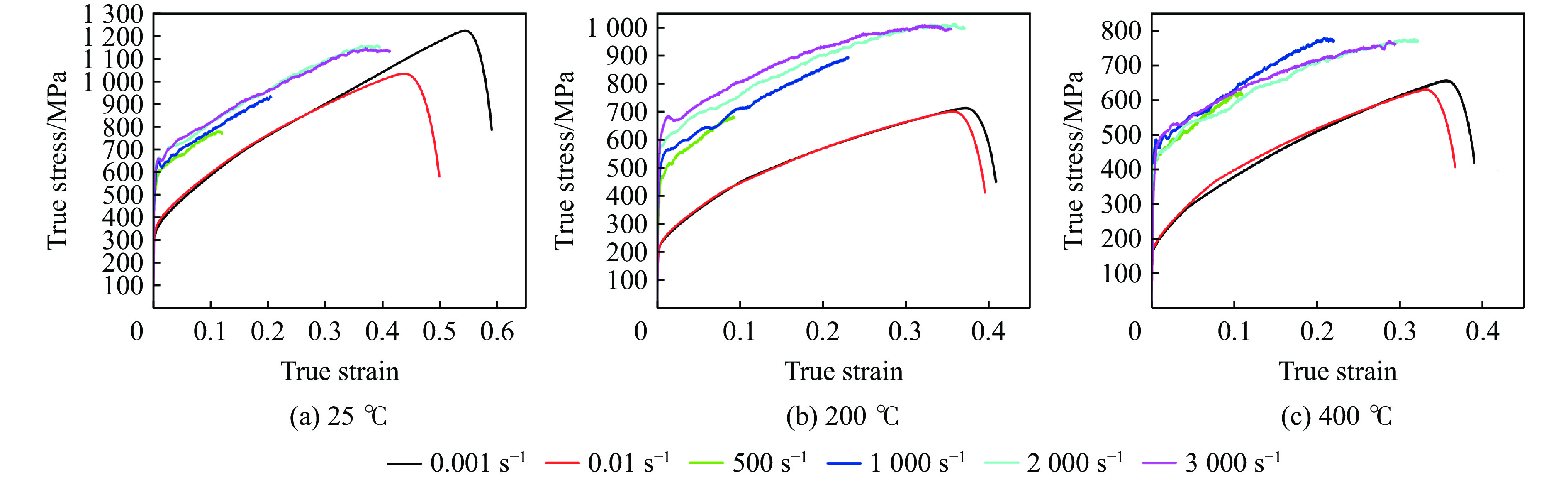
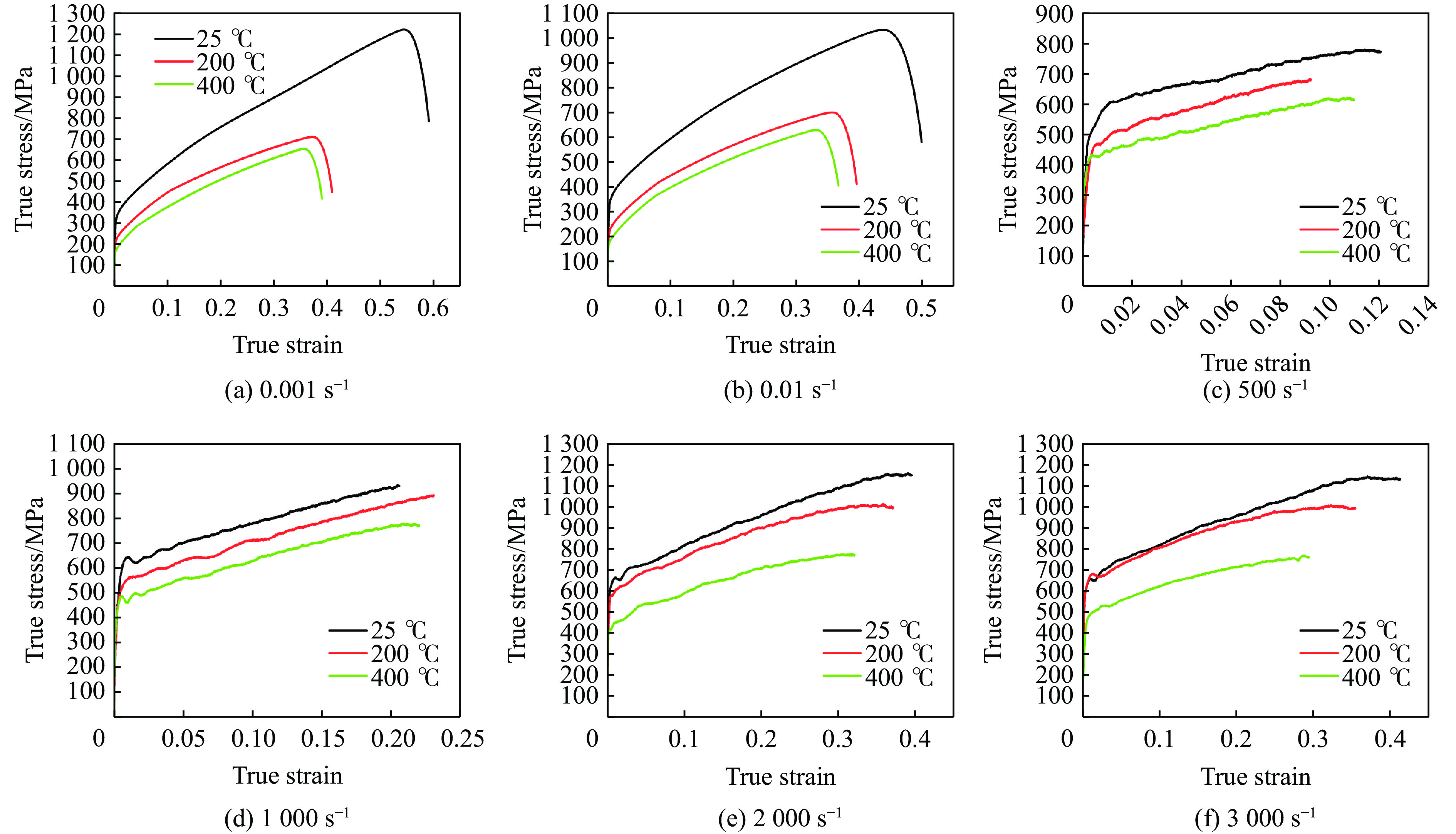
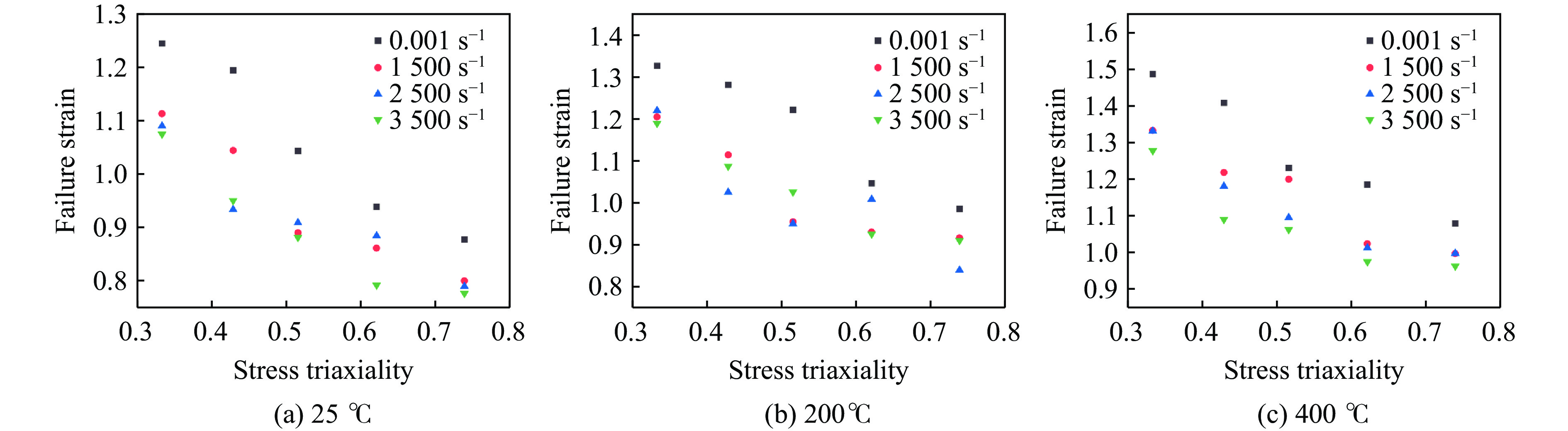
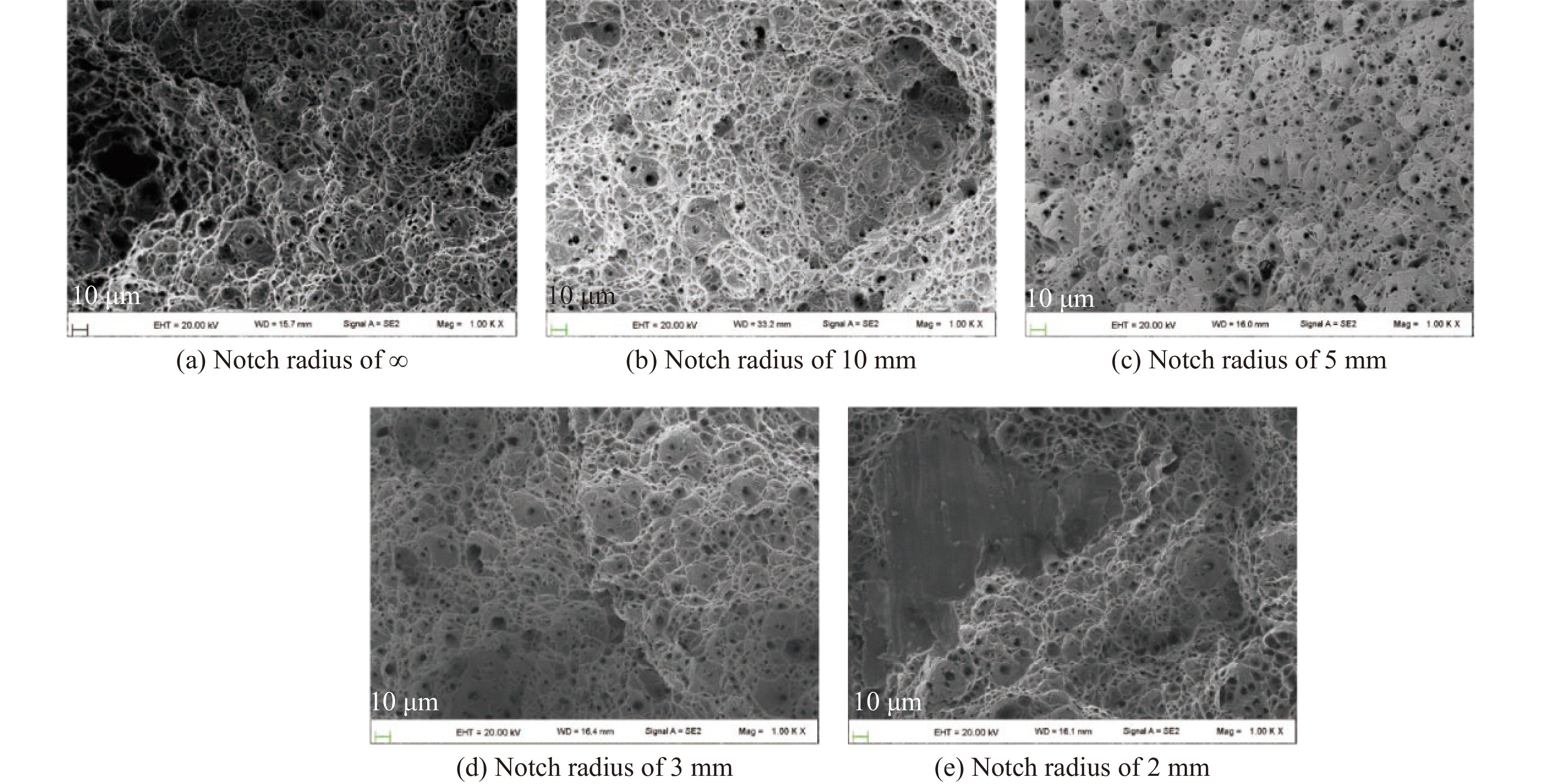
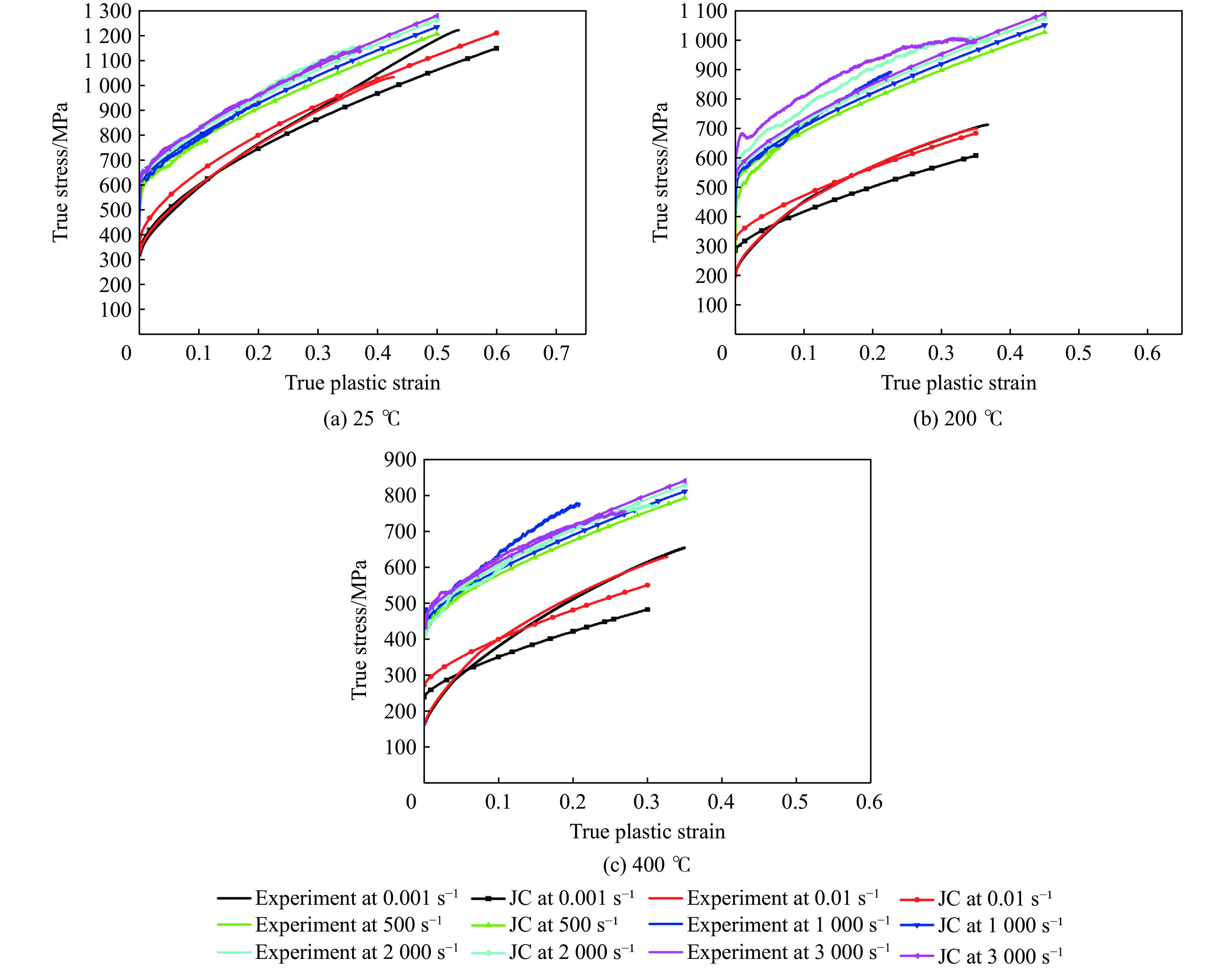
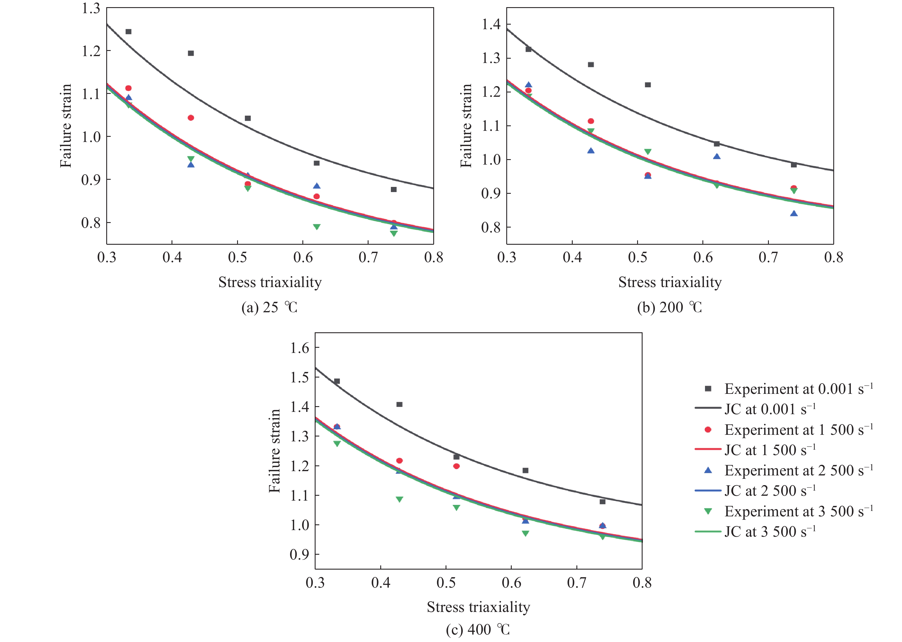
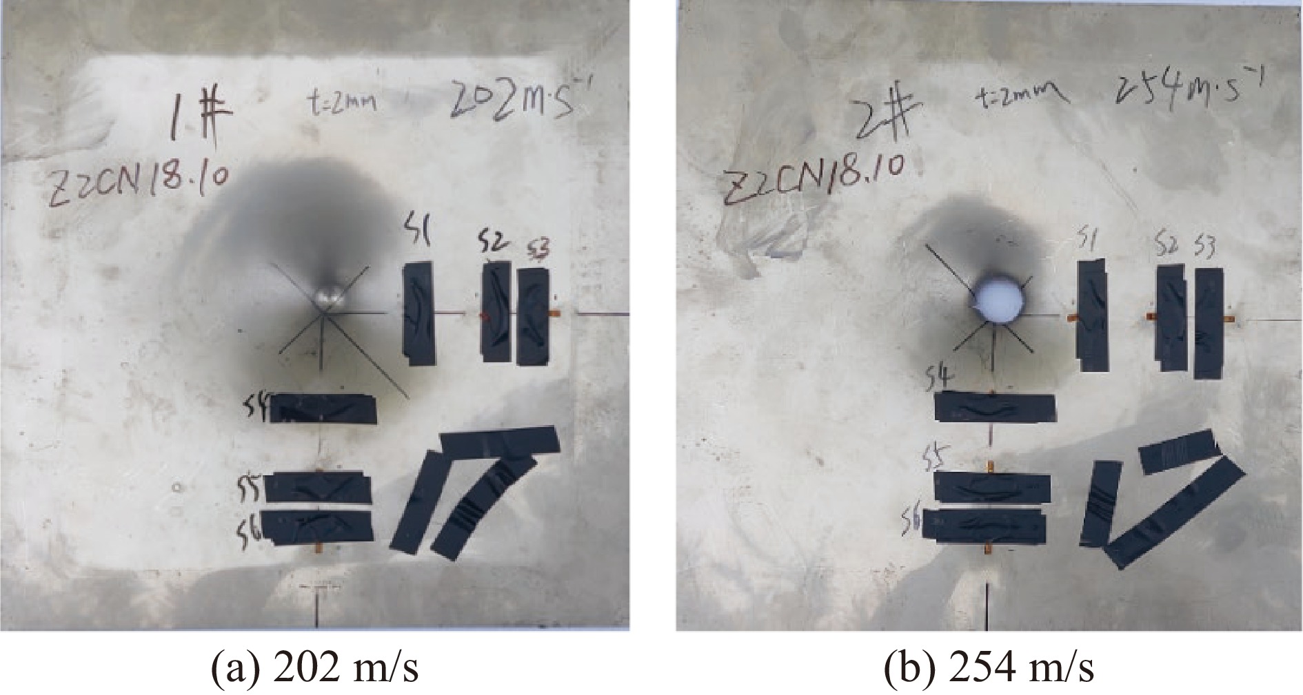
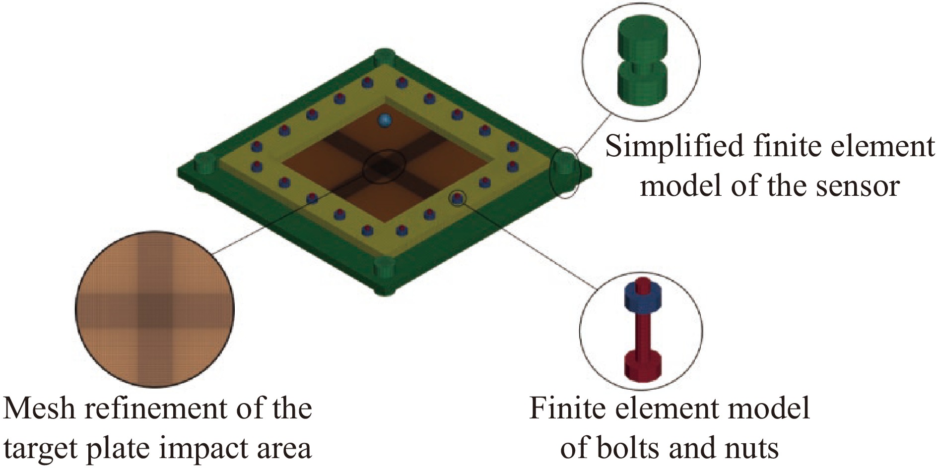
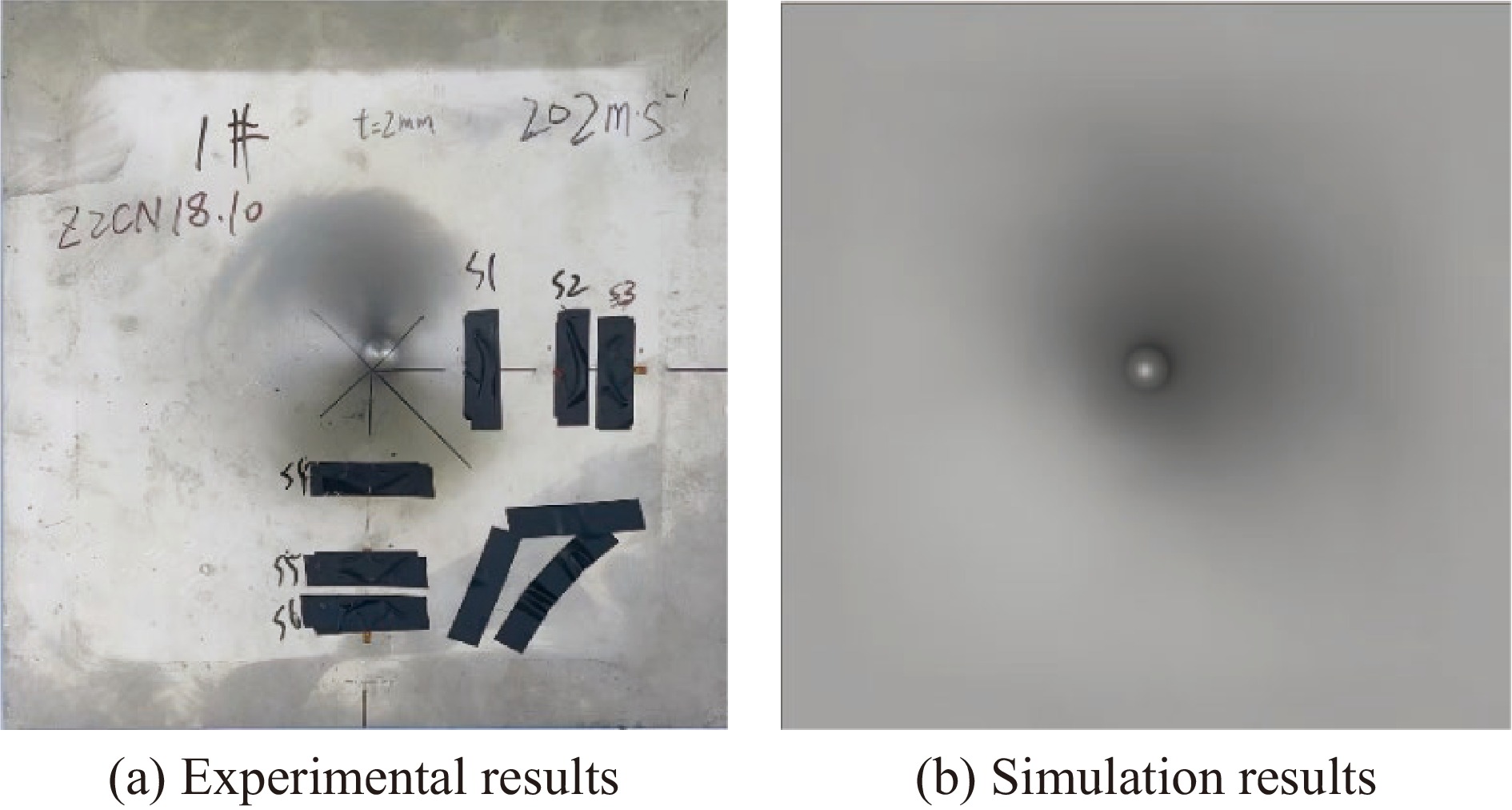
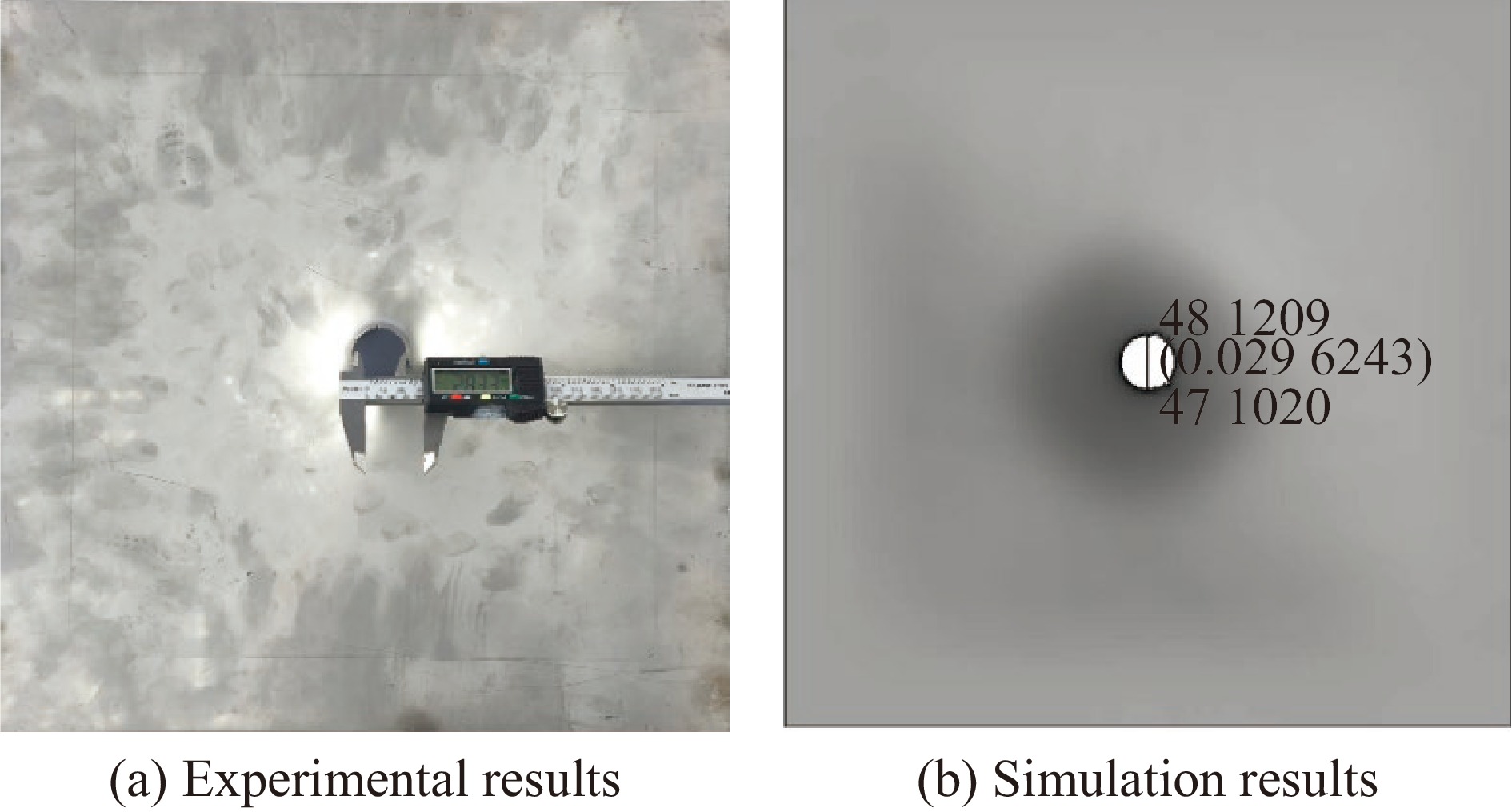
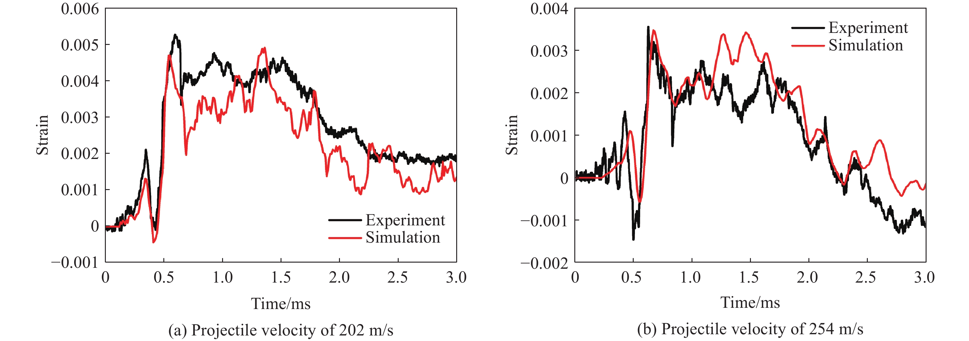
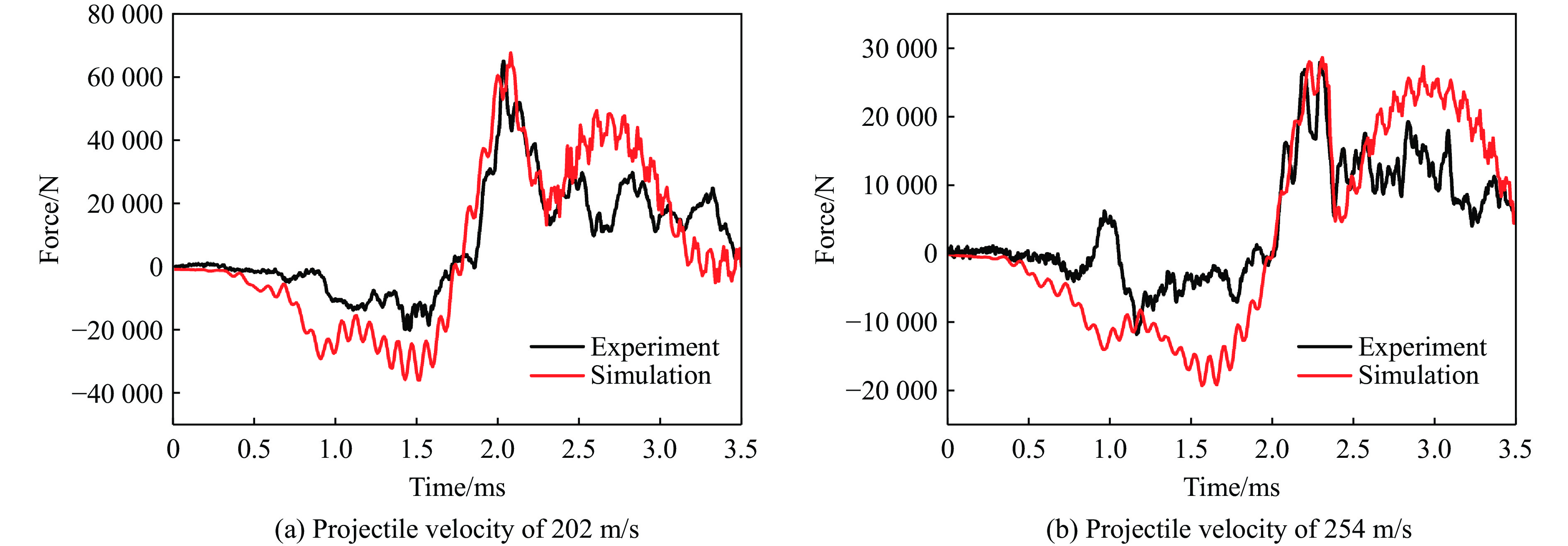
, Available online , doi: 10.11883/bzycj-2025-0243
Abstract:
In the field of material dynamic mechanical properties research, it is significant to obtain reliable data of materials under complex stress states. To address the challenge of achieving a stable stress ratio during combined loading, this work developed a novel device based on the electromagnetic Hopkinson bar (ESHB) platform. This device uniquely enables unilateral synchronous tension/compression-torsion combined dynamic loading. The paper detailed the device’s configuration and loading principles. The core innovation of this device is the independent generation of trapezoidal tensile/compressive and torsional stress waves. A multi-circuit pulse shaper produced tensile/compressive waves, while shear waves were generated using an electromagnetic clamp with torque storage. Crucially, a high-precision digital delay generator (DDG) ensured wave synchronization. With triggering accuracy within 0.1 μs, it controlled the arrival time difference of these distinct waves at the specimen to within 5 μs. This overcame the challenge posed by their different propagation velocities. Additionally, it described the synchronization control methodology and the wave propagation analysis essential for timing calculations. To validate the apparatus, dynamic tension-torsion experiments were conducted on CoCrFeMnNi high-entropy alloy specimens. The results show that the device is highly reliable and effective. It successfully achieved a stable stress ratio of approximately 1.7 throughout the loading duration. Furthermore, the experiments conclusively showed a key finding. Trapezoidal wave loading significantly enhances stress-ratio stability during combined dynamic loading. This improvement contrasts with the effect of traditional sinusoidal wave loading. This advancement offers a robust and controllable experimental method. It enables the study of materials’ dynamic mechanical responses under complex stress states. These states involve high-strain rates and multiaxial loading. This capability is especially valuable for aerospace, impact engineering, and materials science applications. The successful implementation of constant stress-ratio loading opens avenues for more accurate characterization of material yield criteria and failure mechanisms under dynamic multiaxial conditions.
In the field of material dynamic mechanical properties research, it is significant to obtain reliable data of materials under complex stress states. To address the challenge of achieving a stable stress ratio during combined loading, this work developed a novel device based on the electromagnetic Hopkinson bar (ESHB) platform. This device uniquely enables unilateral synchronous tension/compression-torsion combined dynamic loading. The paper detailed the device’s configuration and loading principles. The core innovation of this device is the independent generation of trapezoidal tensile/compressive and torsional stress waves. A multi-circuit pulse shaper produced tensile/compressive waves, while shear waves were generated using an electromagnetic clamp with torque storage. Crucially, a high-precision digital delay generator (DDG) ensured wave synchronization. With triggering accuracy within 0.1 μs, it controlled the arrival time difference of these distinct waves at the specimen to within 5 μs. This overcame the challenge posed by their different propagation velocities. Additionally, it described the synchronization control methodology and the wave propagation analysis essential for timing calculations. To validate the apparatus, dynamic tension-torsion experiments were conducted on CoCrFeMnNi high-entropy alloy specimens. The results show that the device is highly reliable and effective. It successfully achieved a stable stress ratio of approximately 1.7 throughout the loading duration. Furthermore, the experiments conclusively showed a key finding. Trapezoidal wave loading significantly enhances stress-ratio stability during combined dynamic loading. This improvement contrasts with the effect of traditional sinusoidal wave loading. This advancement offers a robust and controllable experimental method. It enables the study of materials’ dynamic mechanical responses under complex stress states. These states involve high-strain rates and multiaxial loading. This capability is especially valuable for aerospace, impact engineering, and materials science applications. The successful implementation of constant stress-ratio loading opens avenues for more accurate characterization of material yield criteria and failure mechanisms under dynamic multiaxial conditions.